Basic Information
Proposal of a new "management and setting" method for sensors


Features
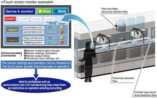
Control and settings can be carried out remotely
Setting and checking incident light intensity for digital sensors FX-501(P), FX-502(P),
LS-501(P)/403, DPS-401(P)/402(P) and analog input unit SC-A01/A02, SC-T1JA that are scattered inside and outside equipment can be carried out remotely for all sensors by using the SC-GU1-485, which greatly improves ease of operations such as monitoring equipment that is running and also equipment starting and maintenance.
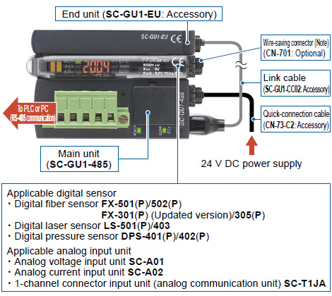
Note:
Used when the output signal is sent via a SC-GU1-485 to the PLC.
If the output signal is sent directly to the PLC, a quick-connection cable(sub cable) (CN-72-C□, CN-71-C□) should be used.
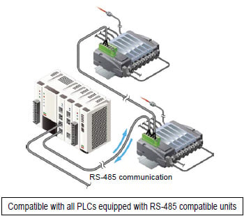
High general applicability so that any type of PLC can be used
RS-485 communication provides a high level of general compatibility so that any type of PLC can be used.
Integration with existing systems is possible without the need to change PLCs.
Features
* The maximum number of units is 12 for configurations including either the FX-501(P)/502(P) or LS-501(P).
- Control and settings can be carried out remotely
- High general applicability so that any type of PLC can be used
- Communication speed 57.6 kbps Series connection of a maximum of 31 nodes is possible
- Up to 16 digital sensors* can be connected side by side
- Save wiring, construction and space
Applications
Centralized control and setting of scattered digital sensors (FX-301/305) is possible using a PLC or personal computer.
Order guide
System configuration
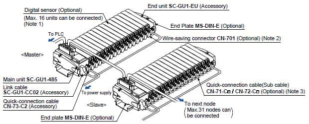
Notes:1) The maximum number of units is 12 for configurations including either theFX-501(P)/502(P)orLS-501(P).2) Used when the output signal is sent via aSC-GU1-485to the PLC.3) Use when wiring output signal lines directly to a PLC. For more information on quick-connection cables, refer tothe instruction manualor this page on the digital sensors used in your environment such as forFX-501(P)/502(P).
Communication unit
| Designation | Model No. | Description |
|---|---|---|
| Main unit | SC-GU1-485 | By the RS-485 communication, centralized control and setting of the individual digital sensors(FX-501/502, LS-403, DPS-401/402) are possible using a PLC or a PC. One unit can connect up to 16 digital sensors.(Note) |
Note : Maximum of 12 units in case of including the FX-500 / LS-500 series.
End plate
End plate is not supplied with the communication unit. Make sure to order it separately.
| Designation | Model No. | Description |
|---|---|---|
| MS-DIN-E | When SC-GU1-485, a sensor amplifier, an analog input unit or an end unit are connected on a DIN rail, these end plates clamp amplifiers into place on both sides. Make sure to use end plates when cascading multiple amplifiers together. 2 pcs. per set |

Option
| Designation | Model No. | Description |
|---|---|---|
| Wire-saving connector | CN-701 | Used when the output signal is sent via a SC-GU1-485 to the PLC, etc. |
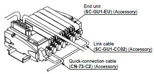
Accessories
- SC-GU1-EU (End unit)
- SC-GU1-CC02 (Link cable)
- CN-73-C2 (Quick-connection cable)
CN-701 (Wire-saving connector)

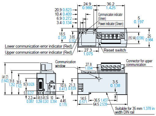
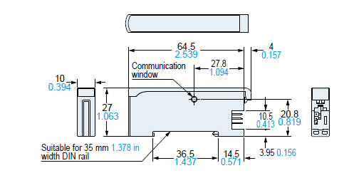
Dimensions
- Unit: mm in
SC-GU1-485
Main unit
SC-GU1-EU
End unit (Accessory)
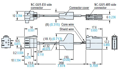
SC-GU1-CC02
Link cable (Accessory)
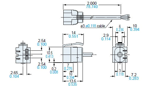
CN-73-C2
Quick-connection cable (Accessory)
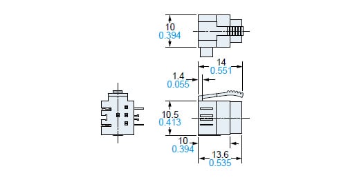
CN-701
Wire-saving connector (Optional)
MS-DIN-E
End plate (Optional)
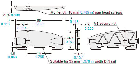
Material: Polycarbonate