Basic Information
Reliable and precise color discrimination


UL : Recognition
Features
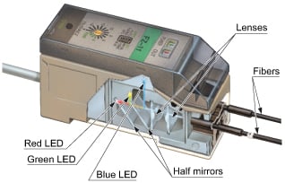
Red, green and blue LEDs
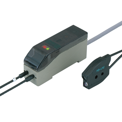
FZ-10 incorporates red, green and blue LEDs as its beam sources, which promise longer lifetime and greater immunity against extraneous light than incandescent lamps and are also maintenance free.
Excellent color detectability
Each of the red, green and blue components is digitally processed so that precise color discrimination is possible.
High-speed response time: 1 ms
Small traveling objects can be sensed even on a highspeed production line, due to its response time of 1 ms.
Easy set up
Just pressing a button recognizes the reference color you want to detect as the criterion. There are two methods to set the criterion, manual teaching and autoteaching. The tolerance adjuster also allows you to set the tolerance of color equivalence in 16 grades.
■Manual teaching
Place an object bearing the reference color under the fiber head and press the teaching button.
■Auto-teaching
Keep pressing the teaching button until an object bearing the reference color travels past the fiber head.
Four types of fibers are available
Four types of fibers are available
Applications
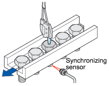
Detecting labels on different colored objects
Even if objects are differently colored, FZ-10 reliably detects the same color label.
Note:
FZ-10 may not be able to detect color depending on object shape, color, glossiness, etc. Please test before actual use and contact our office if you have any questions.
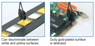
Its precise color resolution discriminates a bare metal surface from a plated metal surface.
Note:
FD-L52 fiber head (high precision type) or FD-L53 fiber head (extremely small spot type) is recommended for applications in which specular objects, having a high reflective index are to be detected, e.g., evaluating if metal objects are plated or not. FD-L54 fiber head (long sensing range type) is recommended for applications where the object wavers on the assembly line.
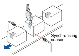
It can reliably detect the presence of a seal on every package in the harmaceutical, cosmetic, food, tobacco, and software industries.
Order guide
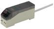
Amplifiers
| Type | Appearance | Model No. | Emitting element | Output |
|---|---|---|---|---|
| NPN output type |
| FZ-11 | Red LED Green LED Blue LED | NPN open-collector transistor |
| PNP output type | FZ-11P | PNP open-collector transistor |
Fibers
| Type | Appearance | Sensing range (Note) | Setting distance | Spot diameter | Fiber cable length | Model No. |
|---|---|---|---|---|---|---|
| Standard |
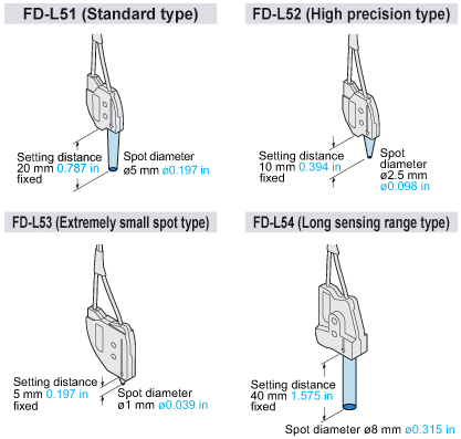
| 14 to 24mm 0.5110.945 in | 20mm 0.787 in (fixed) | ø5mm ø0.197 in (at the setting distance) | 1m 3.281 ft | FD-L51 |
| High precision |
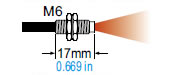
| 8 to 11mm 0.3150.433 in | 10mm 0.394 in (fixed) | ø2.5mm ø0.098 in (at the setting distance) | 1m 3.281 ft | FD-L52 |
| Extremely small spot |
| 4 to 6mm 0.1570.236 in | 5mm 0.197 in (fixed) | ø1mm ø0.039 in (at the setting distance) | 1m 3.281 ft | FD-L53 |
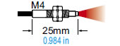
| Long sensing range |
| 30 to 50mm 0.1811.969 in | 40mm 1.575 in (fixed) | ø8mm ø0.315 in (at the setting distance) | 1m 3.281 ft | FD-L54 |
Note:
The sensing range of each fiber is the range for which white non-glossy paper can be detected at the sensitivity for which teaching has been done with a white non-glossy paper (50 × 50 mm 1.969 × 1.969 in) at the respective rated setting distance and at the 16th grade (▲ mark) of tolerance.
Accessory
MS-DIN-3 (Amplifier mounting bracket)

[Notice] General-purpose fibers can also be combined
Color difference distinction by combining general-purpose fibers FD-62/61G/61/42G and FZ-10 series amplifiers is also possible.
General-purpose fibers have a small tip, and are a free-cut type that where you can cut the fiber length to the desired length, so they can be installed small spaces.
FD-62
Setting distance:8 mm0.315 in(fixed)
FD-61G / FD-61
Setting distance:5 mm0.197 in(fixed)
FD-42G
Setting distance:4 mm0.157 in(fixed)
Note: They cannot be used for applications requiring detection precision.
Dimensions
- Unit: mm in
FZ-11 FZ-11P
Amplifier
Assembly dimensions with attached amplifier mounting bracket
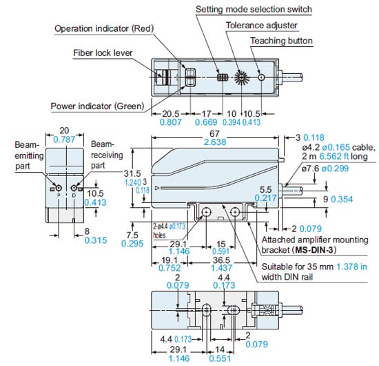
Note:The top view is shown without the cover.
MS-DIN-3
Amplifier mounting bracket (Accessory for FZ-11□)
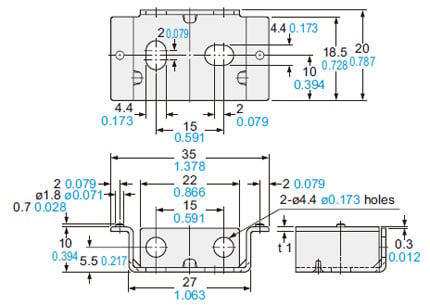
Material:Cold rolled carbon steel (SPCC)(Uni-chrome plated)
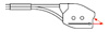
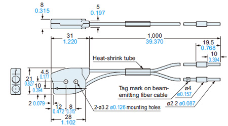
FD-L51
Fiber
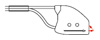
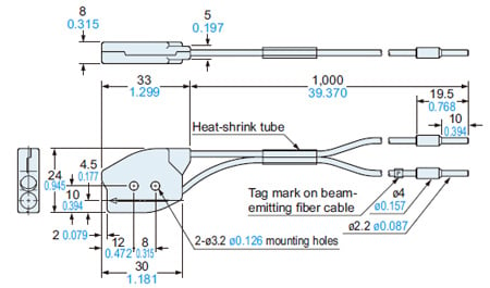
FD-L52
Fiber
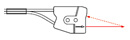
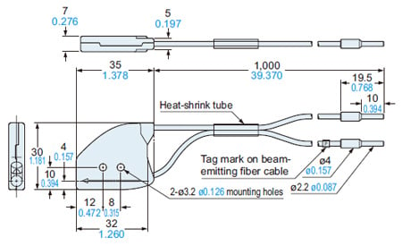
FD-L53
Fiber
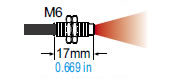
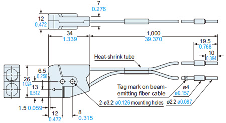
FD-L54
Fiber
I/O Circuit and Wiring diagrams
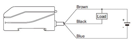
NPN output type (FZ-11)
I/O circuit diagram
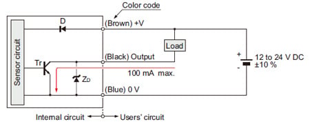
Symbols・・・
D : Reverse supply polarity protection diode
ZD: Surge absorption zener diode
Tr: NPN output transistor
Wiring diagram
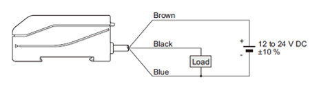
PNP output type (FZ-11P)
I/O circuit diagram
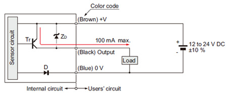
Symbols・・・
D : Reverse supply polarity protection diode
ZD: Surge absorption zener diode
Tr: PNP output transistor
Wiring diagram
Setting
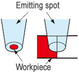
・During teaching, the FZ-10 series resolves the color projected by the spot into red, green, and blue components which are processed as numerical values and stored into the EEPROM memory. If, during teaching, the spot area is not filled by one uniform color, such as when the target objects are smaller than the spot area, or are partly projected upon, then colors other than the one you want to detect may also be sensed. Make sure that objects fill the whole spot area during teaching, as well as, sensing. The taught data is saved in the EEPROM even when the sensor power supply is switched off. However, the guaranteed rewrite operations are limited to 100,000 times because of its lifetime.
・To manipulate the DIP switches, use a pair of tweezers, etc., with a tip width of 0.8 mm 0.031 in approx.
Procedure
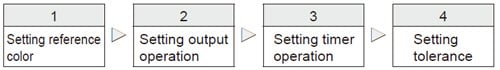
Setting tolerance
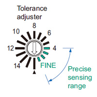
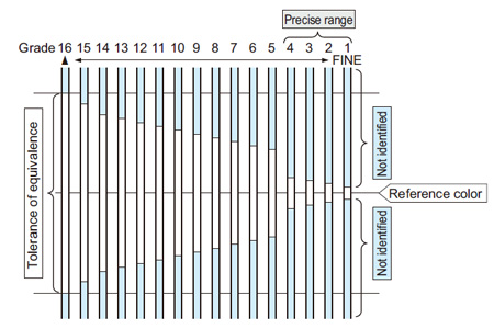
- The tolerance adjuster determines the tolerance of equivalence with respect to the reference color in 16 grades.
- Set the arrow mark of the adjuster to the desired grade from 1st to 16th using the adjusting screwdriver.
- When the grade is changed, the output is turned ON, once, for resetting.
- Even if the grade is changed, the reference color taught earlier does not change until the sensor is taught again.
- When performing auto-teaching, it is possible that teaching may fail depending upon the tolerance grade. If this happens, change the tolerance grade and repeat the teaching.
- For 16th to 5th grade, color identification is done based upon the color (red, green, blue) component ratio. For 4th to 1st grade (precise range), brightness is also considered for color identification. Hence, when the adjuster is set to the FINE side (4th to 1st grade), minute differences in gloss or color shades are also detected.
Others
- Do not use during the initial transient time (0.5 sec.) after the power supply is switched on.
- Periodical teaching should be done to maintain stable sensing condition.
Fiber
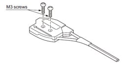
Mounting
- Mount with two M3 screws with a tightening torque of 0.5 N・m or less.
- Several fiber heads of FD-L51, FD-L52, FD-L53 and FD-L54 can be mounted close together as long as their emitted spots do not overlap.
Others
- If the bending radius is smaller than the allowable value, the sensing performance may deteriorate.
- Wipe dirt or stains from the sensing faces with a soft cloth. Do not use any organic solvent for cleaning.
- Ensure that any strong extraneous light is not incident on the receiving face of the fiber head.
- Do not move or bend the fiber cable after the sensitivity setting. Detection may become unstable
- Keep the fiber head surface intact. If it is scratched or spoiled, the detectability will deteriorate.
- Do not expose the fiber cable to any organic solvents.
- Ensure that the fiber head is not directly exposed to water. A water drop on the fiber head deteriorates the sensing.
- Do not apply excessive tensile force to the fiber cable.