Basic Information
Just "Look" and "Turn", simple, easy-to-use fiber sensor


UL : Recognition(Excluding FX-412□)
Features
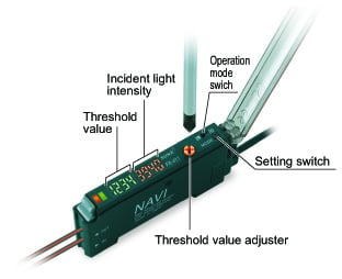
Incident light intensity and threshold value are displayed simultaneously
The incident light intensity and threshold value can be checked at the same time with no operations needed. In addition, no complex mode settings are needed when the values are adjusted.
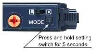
Easy-to-understand operating panel layout
The threshold value adjuster and operation mode switch are large and easy to see, and they can be operated with the same sensitivity as general-purpose photoelectric sensors. Functions which are not commonly used can be operated using a non-obtrusive setting switch.
Adjustment variations according to the individual have been eliminated
Accurate control of the adjuster threshold values by using numerical values is possible due to the digital display. This allows anybody to perform the same settings.
Threshold values can be changed smoothly
This sensor uses the R.S.S.* adjuster with a compact encoder inside. The sensitivity amount changes depending on the rotation speed of the adjuster, so that adjustment can be carried out speedily.
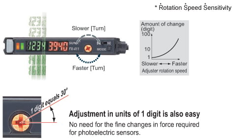
Large endless adjuster
Standard screwdrivers can be used to turn the adjuster as well as precision screwdrivers. In addition, an "endless" mechanism is used which eliminates the possibility of any damage being caused by turning the adjuster too far.

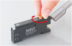
FX-412 can be turned by finger!
The adjuster can be turned directly by finger, without the need for a screwdriver.
Beam power greatly increased to give strong performance under adverse environments [Red LED type]
The beam power has been greatly increased. This means a longer sensing distance and less trouble from problems such as dust. These sensors have ample performance for workplace needs.
![Beam power greatly increased to give strong performance under adverse environments [Red LED type]](https://tp.industry.panasonic.com/hubfs/pid-corp/products/fasys/sensor/fiber/fx-411/images/pic09.jpg)
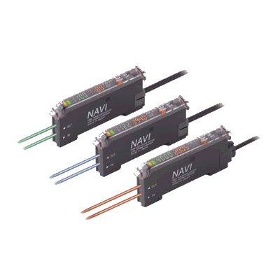
Three types are available, with red, blue and green light
Different sensors can be selected to suit the application.
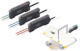
Color combinations that can be discerned during mark sensing

Improved stability over both long and short terms [Red LED type]
The red LED type sensors have a "four-chemical emitting element" which maintains stability of light emissions for long-term operation. Furthermore, all models have an "APC (Auto Power Control) circuit" which improves stability at times such as when the power is turned on. These features improve overall stability compared to previous models.
![Improved stability over both long and short terms [Red LED type]](https://tp.industry.panasonic.com/hubfs/pid-corp/products/fasys/sensor/fiber/fx-411/images/pic12.jpg)
Excellent workability and ease of maintenance [Connector type]
The same quick-connection cable that is used for sensors such as the FX-300 series of digital fiber sensors is used. This means that they can be used together with other types of sensors such as laser sensors, and the number of power supply cables can be reduced.
![Excellent workability and ease of maintenance [Connector type]](https://tp.industry.panasonic.com/hubfs/pid-corp/products/fasys/sensor/fiber/fx-411/images/pic13.jpg)
The sensors can be connected together with other sensors such as the FX-300 series of digital fiber sensors and the GA-311 of inductive proximity sensors. In addition, the SC series of sensor PLC connection units with MIL connector compatibility can also be used to further reduce the amount of wiring.
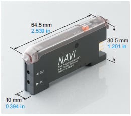
Contributing to device miniaturization
This fiber sensor is the smallest among the dual digital display types, contributing to device miniaturization.
Ideal for dealing with saturation / Light-emitting amount selection function [Red LED type]
In cases where the incoming light level can become saturated, such as during close-range sensing or when sensing transparent or minute objects, the sensor's lightemitting amount can be adjusted to provide more stable sensing without changing the response time.
![Ideal for dealing with saturation / Light-emitting amount selection function [Red LED type]](https://tp.industry.panasonic.com/hubfs/pid-corp/products/fasys/sensor/fiber/fx-411/images/pic15.jpg)
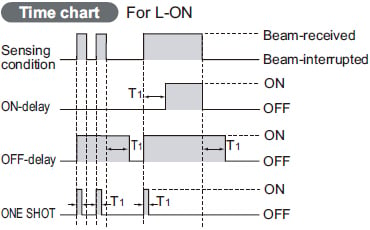
Equipped with 3 types timers
Equipped with OFF-delay / ON-delay / ONE SHOT timer.
(Timer period: 1 to 3 sec. approx.)
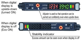
Digital display upside-down / off function
The digital display can be turned upside-down if required to suit the setup location. In addition, a stability indicator is also provided, so that the amount of light-receiving excess can be checked even when the display is turned off.
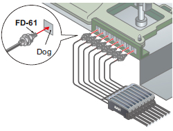
Interference prevention for up to 8 sets fiber heads (for U-LG)
The optical communication function allows up to a maximum of eight sets of fiber heads (four sets for FAST and STD settings) to be installed in contact with each other without mutual interference occurring. (Set automatically when power is turned on.)
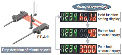
Hold function
Peak and bottom hold values for the incident light intensity can be displayed. This is useful for checking the incident light intensity during tasks such as drop detection.
In addition, the peak and bottom values can be checked while looking at the threshold value, which makes adjustment much easier.
Key lock function prevents wrong operation
This prevents the operator from changing the threshold value by mistake.
Order guide
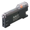
Amplifiers
Quick-connection cable is not supplied with the amplififier. Please order it separately.
| Type | Appearance | Model No. | Emitting element | Output |
|---|---|---|---|---|
| NPN Output |
| FX-411 | Red LED | NPN open-collector transistor |
| FX-411B | Blue LED | |||
| FX-411G | Green LED | |||
| PNP Output | FX-411P | Red LED | PNP open-collector transistor | |
| FX-411BP | Blue LED | |||
| FX-411GP | Green LED | |||
| NPN Output |
| FX-412(Note) | Red LED | NPN open-collector transistor |
| FX-412B(Note) | Blue LED | |||
| FX-412G(Note) | Green LED |
(Note):The FX-412□ has a threshold value adjuster that can be adjusted with your fingers.
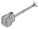
Quick-connection cables
Quick-connection cable is not supplied with the amplififier. Please order it separately.
| Type | Model No. | Description | |
|---|---|---|---|
| Main cable (3-core) | CN-73-C1 | Length: 1 m 3.281 ft | 0.2 mm2 3-core cabtyre cable, with connector on one end Cable outer diameter: ø3.3 mm ø0.130 in |
| CN-73-C2 | Length: 2 m 6.562 ft | ||
| CN-73-C5 | Length: 5 m 16.404 ft | ||
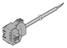
| Sub cable (1-core) | CN-71-C1 | Length: 1 m 3.281 ft | 0.2 mm2 1-core cabtyre cable, with connector on one end Cable outer diameter: ø3.3 mm ø0.130 in |
| CN-71-C2 | Length: 2 m 6.562 ft | ||
| CN-71-C5 | Length: 5 m 16.404 ft | ||
(Note):The material of Quick-connection cable will be changed from production in March 2013, as soon as the previous ones are shipped out.
・Conductor cross-sectional area has been changed from 0.15mm2 to 0.2mm2.
・Sheath diameter has been changed from ø3.0mm to ø3.3mm.
Main cable
CN-73-C□
Sub cable
CN-71-C□
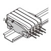
End plates
End plates are not supplied with the amplifier. Please order them separately when the amplifiers are mounted in cascade.
| Appearance | Model No. | Description |
|---|---|---|
| MS-DIN-E | When amplifiers are mounted in cascade, or when an amplifier moves depending on the way it is installed on a DIN rail, these end plates clamp amplifiers into place on both sides. Make sure to use end plates when cascading multiple amplifiers together. Two pcs. per set |
Option
| Designation | Model No. | Description |
|---|---|---|
| Amplifier mounting bracket | MS-DIN-2 | Mounting bracket for amplifier |
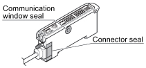
| Fiber amplifier protection seal | FX-MB1 | 10 sets of 2 communication window seals and 1 connector seal Communication window seal: It prevents malfunction due to transmission signal from another amplifier, as well as, prevents effect on another amplifier. Connector seal: It prevents contact of any metal, etc., with the pins of the quick-connection cable. |
Amplifier mounting bracket
MS-DIN-2
Fiber amplifier protection seal
FX-MB1
Recommended e-CON connector
Manufactured by 3M Japan Limited
Adapted connector:37104-3101-000 FL
Please refer to "Introducing the 3M™ mini-clamp connector" for details.
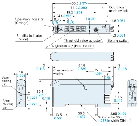
Dimensions
- Unit: mm in
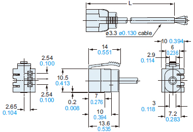
FX-411□
FX-411□P
Amplifier
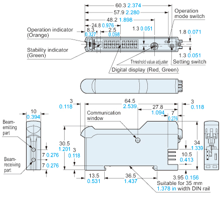
FX-412□
Amplifier
CN-71-C1
CN-71-C2
CN-71-C5
Sub cable (Optional)

• Length L
| Model No. | Length L |
|---|---|
| CN-71-C1 | 1,000 39.370 |
| CN-71-C2 | 2,000 78.740 |
| CN-71-C5 | 5,000 196.850 |
CN-73-C1
CN-73-C2
CN-73-C5
Main cable (Optional)
• Length L
| Model No. | Length L |
|---|---|
| CN-73-C1 | 1,000 39.370 |
| CN-73-C2 | 2,000 78.740 |
| CN-73-C5 | 5,000 196.850 |
MS-DIN-E
End plate (Optional)
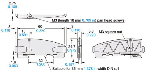
Material: Polycarbonate
MS-DIN-2
Amplifier mounting bracket (Optional)
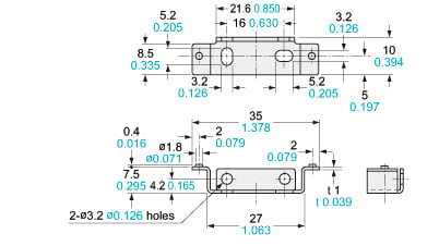
Material:Cold rolled carbon steel (SPCC)(Uni-chrome plated)
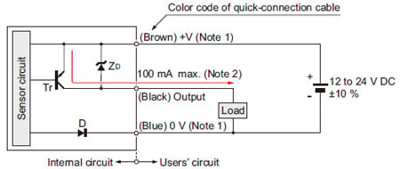
I/O Circuit and Wiring diagrams
NPN output type
FX-41□
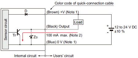
Notes:
1)The quick-connection sub cable does not have +V (brown) and 0 V (blue). The power is supplied from the connector of the main cable.
2)50 mA max., if five amplifiers, or more, are connected together.
Symbols・・・
D : Reverse supply polarity protection diode
ZD: Surge absorption zener diode
Tr: NPN output transistor
PNP output type
FX-41□P
Notes:
1)The quick-connection sub cable does not have +V (brown) and 0 V (blue). The power is supplied from the connector of the main cable.
2)50 mA max., if five amplifiers, or more, are connected together.
Symbols・・・
D : Reverse supply polarity protection diode
ZD: Surge absorption zener diode
Tr : PNP output transistor
回路・接続
NPN出力タイプ
FX-41□(-C2)

(注1): ワンタッチケーブルの子ケーブルには、+V(茶)および0V(青)は装備されていません。電源は、親ケーブルのコネクタ部より供給されます。
(注2): コネクタタイプ連結5台以上の場合、50mA MAX.となります。
記号・・・ D : 電源逆接続保護用ダイオード
ZD: サージ電圧吸収用ツェナーダイオード
Tr: NPN出力トランジスタ
PNP出力タイプ
FX-41□P(-C2)

(注1): ワンタッチケーブルの子ケーブルには、+V(茶)および0V(青)は装備されていません。電源は、親ケーブルのコネクタ部より供給されます。
(注2) コネクタタイプ連結5台以上の場合、50mA MAX.となります。
記号・・・ D : 電源逆接続保護用ダイオード
ZD: サージ電圧吸収用ツェナーダイオード
Tr : PNP出力トランジスタ
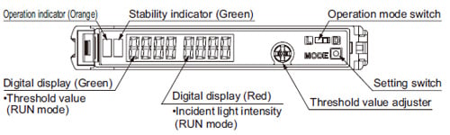
Part description
Wiring
- Make sure that the power supply is off while wiring.
- Verify that the supply voltage variation is within the rating.
- Take care that if a voltage exceeding the rated range is applied, or if an AC power supply is directly connected, the product may get burnt or damaged.
- In case noise generating equipment (switching regulator, inverter motor, etc.) is used in the vicinity of this product, connect the frame ground (F.G.) terminal of the equipment to an actual ground.
- If power is supplied from a commercial switching regulator, ensure that the frame ground (F.G.) terminal of the power supply is connected to an actual ground.
- Take care that short circuit of the load wrong wiring may burn or damage the product.
- Do not run the wires together with high-voltage lines or power lines or put them in the same raceway. This can cause malfunction due to induction.
- Extension up to total 100 m 328.084 ft (if 5 to 8 units are connected in cascade: 50 m 164.042 ft, if 9 to 16 units are connected in cascade: 20 m 65.617 ft) is possible with 0.3 mm2, or more, cable. However, in order to reduce noise, make the wiring as short as possible.
- Take care that cable extension increases the residual voltage.
Mounting
・
Make sure that the power supply is off while connecting / disconnecting the amplifiers and the quick-connection cables.
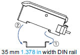
How to mount the amplifier
①Fit the rear part of the mounting section of the amplifier on a width DIN rail.
②Press down the rear part of the mounting section of the unit on the width DIN rail and fit the front part of the mounting section to the DIN rail.
How to remove the amplifier
①Push the amplifier forward.
②Lift up the front part of the amplifier to remove it.
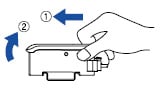
Note:Take care that if the front part is lifted without pushing the amplifier forward, the hook on the rear portion of the mounting section is likely to break.
Fiber installation
・Insert the fiber into the amplifier after attaching the attachment. Refer to the "Instruction Manual" included with the fiber for details.
①Push the fiber lock lever down.
②Slowly insert the fiber into the insertion slot until it stops. (Note 1)
③Push the fiber lock lever back up until it stops.
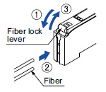
Notes:
1)Note that if the fiber is not fully inserted, the sensing distance will decrease. Also note that the bending-resistant fiber may bend during insertion.
2)In case of coaxial reflective type fibers, mount the central fiber (single-core) to the emitter part and the peripheral fiber (multi-core) to the receiver. Note that sensing precision will deteriorate when done in reverse.
・Make sure that the power supply is off while adding or removing the amplifiers.
・Make sure to check the allowable ambient temperature, as it depends on the number of amplifiers connected in cascade.
・In case two, or more, amplifiers are connected in cascade, make sure to mount them on a DIN rail.
・When the amplifiers move on the DIN rail depending on the attaching condition or the amplifiers are mounted close to each other in cascade, fit them between the optional end plates (MS-DIN-E) mounted at the two ends.
・Up to maximum 15 amplifiers can be added (total 16 amplifiers connected in cascade.)
・When connecting more than two amplifiers in cascade, use the sub cable (CN-71-C□) as the quickconnection cable for the second amplifier onwards.
・When connecting amplifiers not close to each other in parallel, be sure to mount the optional end plate (MS-DIN-E) at both sides of each amplifier or affix the communication window seal of the optional fiber amplifier protection seal (FX-MB1) to the communication windows. For details, refer to the instruction manual enclosed with the FX-MB1.
・When the different LED (red / blue / green) types are connected in cascade, mount the identical models together.
・When this product is used with the other digital fiber amplifiers, be sure to place this product to the left most position (When you look from the connector side). If this product is not placed to the leftmost position, this product may not operate properly.
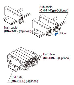
Cascading method
①Mount the amplifiers, one by one, on the DIN rail.
②Slide the amplifiers next to each other, and connect the quick-connection cables.
③Mount the optional end plates (MS-DIN-E) at both the ends to hold the amplifiers between their flat sides.
④ighten the screws to fix the end plates.
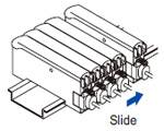
Dismantling
①Loosen the screws of the end plates.
②Remove the end plates.
③Slide the amplifiers and remove them one by one.
Switching output operation
When set to Dark-ON (D-ON)
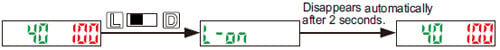
- The operation selection switch can be used to display different output operations (L-ON / D-ON) on the digital display.
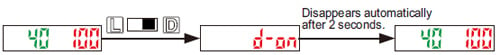
When set to Light-ON (L-ON)
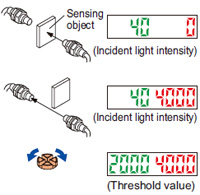
Threshold value (sensitivity) adjustment
①Check the incident light intensity [in the digital display (red)] when a sensing object is placed in the sensing position.
②Check the incident light intensity [in the digital display (red)] when the sensing object is removed from the sensing position.
③Turn the threshold value adjuster to the threshold value [in the digital display (green)] that is the value in between ① and ②. (The threshold value is automatically written to the EEPROM.)
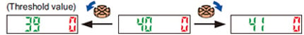
Threshold value setting method
- When the threshold value adjuster is turned clockwise, the threshold value increases. When the threshold value adjuster is turned counterclockwise, the threshold value decreases.
・If there is a sufficient level of margin in the incident light intensity, the stability indicator (green) will light up.
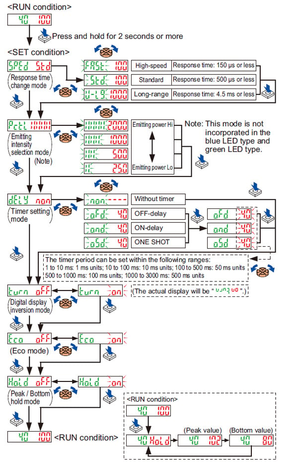
Mode selection
- When the setting switch is pressed and held for 2 sec. or more, “SET” mode (mode setting screen) is activated.
- If the setting switch is pressed while in “SET” mode, the mode will change.
- If the threshold value adjuster is turned while a mode is active, the setting item will change and blink.
- When the setting switch is pressed at the item you would like to set, it blinks 3 times and then the setting is confirmed and the mode switches to the next mode.
- If the setting switch is pressed and held for 2 sec. or more or do not press any key for 15 sec. while “SET” mode is active, the mode will switch automatically to “RUN” mode.
Mode table
| Mode | Factory setting | Description |
|---|---|---|
| Response time change mode | The response time can be set. | |
| Light-emitting amount selection mode (Note 1) | The light-emitting amount can be switched among four levels. | |
| Timer setting mode | Timer settings can be selected; Without timer / OFF-delay timer / ON-delay timer / ONE SHOT timer. Also the timer period can be set. | |
| Digital display inversion mode | The display on the digital display can be inverted. | |
| Eco mode (Note 2) | If no key is pressed for 20 sec. approx. while in “RUN” mode, the digital display turns off automatically. Press the setting switch or move the operation mode switch to make the display light up again. The digital display will light up when the threshold value adjuster is turned, but note that this will also cause the threshold value to change. | |
| Peak / Bottom hold mode | If the setting switch is pressed while “RUN” mode is active, the display will alternate between the peak hold value and the bottom hold value. (The display will refresh every 2 sec.) The display will return to normal if any operation other than threshold value setting is carried out. |
Notes:
1)This mode is not incorporated in the blue LED type and green LED type.
2)While the peak / bottom hold mode is ON, the digital display is not turned off even if the Eco mode is set to ON.
Key lock function
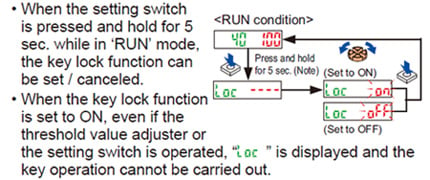
Note:Although the display changes to the indication of ‘SET’ condition 2 sec. after pressing the setting switch, keep pressing the switch. Furthermore, the sensor does not go into the key lock setting from ‘SET’ condition.
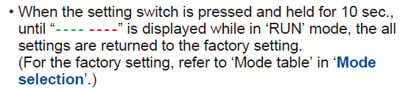
Factory setting
Error display indicator readings
| Display | Error description | Measures |
|---|---|---|
| The load has short-circuited and excess current is flowing. | Turn off the power, then check the load. | |
| Communication error has occurred at time of connection. | Check if the mounted amplifiers are in close contact with each other. |
Others
- This product has been developed / produced for industrial use only.
- Do not use during the initial transient time (0.5 sec.) after the power supply is switched on.
- This sensor is suitable for indoor use only.
- Do not use this sensor in places having excessive vapor, dust, etc., or where it may come in contact with corrosive gas.
- Take care that the sensor does not come in direct contact with oil, grease, organic solvents, such as, thinner etc., or strong acid, and alkaline.
- This sensor cannot be used in an environment containing inflammable or explosive gases.
- Never disassemble or modify the sensor.
- The changes to the settings are written to the EEPROM, but because the EEPROM has a limited service life, you should avoid changing the settings any more than 1 million times.
各部の名称
配線
- 誤配線をすると、故障の原因となります。
- 電源入力は、定格を超えないよう電源変動をご確認ください。
- 定格範囲以上の電圧の印加や、直接交流電源に接続すると、破損や焼損のおそれがありますので、ご注意ください。
- センサ取り付け部周辺にノイズ発生源となる機器(スイッチングレギュレータ、インバータモータなど)をご使用の場合は、機器のフレームグランド(F.G.)端子を必ず接地してください。
- 電源に市販のスイッチングレギュレータをご使用になる場合には、必ず電源のフレームグランド(F.G.)端子を接地してください。
- 負荷の短絡や誤配線は、破損や焼損のおそれがありますので、ご注意ください。
- 高圧線や動力線との並行配線や、同一配線管の使用は避けてください。誘導による誤動作の原因となります。
- ケーブル延長する場合は、0.3mm2以上のケーブルにて全長100m(5~8台増設時:50m、9~16台増設時:20m)まで可能です。但し、ノイズを避けるため、配線はできる限り短くしてください。
- ケーブル延長をすると残留電圧が増加しますので、ご注意ください。
取り付け
- アンプの取り付け/取り外し、およびワンタッチケーブルの取り付け/取り外しは、必ず電源を切ってから行なってください。

[1] エンドプレートのビスを緩めます。
[2] エンドプレートを取り外します。
[3] アンプをスライドさせて、1台ずつ取り外します。
出力動作の切り換えについて
動作切換スイッチを切り換えると、出力動作(L-ON/D-ON)がデジタル表示部に表示されます。
非入光時ON(D-ON)に設定する場合

入光時ON(L-ON)に設定する場合

しきい値(感度)調整

[1] 検出物体を検出位置に置いた状態の入光量[デジタル表示部(赤色)]を確認します。
[2] 検出物体を取り除いた状態の入光量[デジタル表示部(赤色)]を確認します。
[3] しきい値調整ボリウムを回して1と2の中間の値にしきい値[デジタル表示部(緑色)]を設定します。
(しきい値は自動的にEEPROMに記憶されます。)
しきい値の設定方法
しきい値調整ボリウムを時計方向に回すとしきい値が上がります。
また、しきい値調整ボリウムを反時計方向に回すとしきい値が下がります。

- 入光量がしきい値に対して充分な余裕度がある場合、安定表示灯(緑色)が点灯します。
モード切り換えについて
- 設定スイッチを2秒間長押しすると、“SET”状態(モード設定画面)になります。
- “ SET”状態時に設定スイッチを押すと、モードが切り換わります。
- モード時に、しきい値調整ボリウムを回すと設定項目が切り換わり点滅します。
- 設定したい項目で設定スイッチを押すと、3回点滅後に設定が確定され次のモードへ移ります。
- “ SET”状態のモード時に、設定スイッチを2秒以上長押しするか、15秒間キー操作が行なわれないと自動的に“RUN”状態に切り換わります。
モード一覧
| モード | 工場出荷時の設定 | 内 容 |
|---|---|---|
| 応答時間切換モード |  | 応答時間の設定ができます。 |
| 投光量可変モード (注1) |  | 投光量を4段階で変更することができます。 |
| タイマ設定モード |  | 「タイマなし」、「オフディレイタイマ」、「オンディレイタイマ」、「ワンショットタイマ」を選択できます。また、タイマ時間も設定できます。 |
| 表示反転モード |  | デジタル表示部の表示を反転させることができます。 |
| Ecoモード (注2) |  | “RUN”状態で約20秒間キー操作を行なわないと、自動的にデジタ ル表示部が消灯します。設定スイッチを押すか、動作切換スイッチを切り換えると、デジタル表示部が点灯します。しきい値調整ボリウムを回してもデジタル表示部が点灯しますが、しきい値が変更されますのでご注意ください。 |
| ピーク・ボトム ホールドモード |  | “RUN”状態で設定スイッチを押すと、ピークホールド値、ボトムホー ルド値が交互に表示されます(2秒周期で更新されます)。しきい値設定以外の操作を行なうと表示は解除されます。 |
(注1): 青色光タイプおよび緑色光タイプには、装備されていません。
(注2): ピーク・ボトムホールド表示時には、EcoモードをONに設定してもデジタル表示部は消灯しません。

キーロック機能の設定について

(注1):設定スイッチを押して2秒後に“SET”状態の表示に切り換わりますが、そのまま押し続けてください。
また、“SET”状態からキーロック機能設定に切り換えることはできません。
工場出荷時の設定について

エラー表示ついて
| 表 示 | エラー内容 | 処 理 |
|---|---|---|
| 負荷が短絡して過電流が流れています。 | 電源を切ってから負荷を確認してください。 | |
| 連結時の通信エラーです。 | 各アンプが離れていないかを確認してください。 |
その他
- 本製品は、工業環境に使用する目的で開発/製造された製品です。
- 電源投入時の過渡的状態(0.5s)を避けてご使用ください。
- 屋外で使用しないでください。
- 蒸気、ホコリなどの多い所での使用は避けてください。
- シンナーなどの有機溶剤や強い酸、アルカリ、水、油、油脂が直接かからないようにご注意ください。
- 引火性、爆発性ガスの雰囲気中での使用はできません。
- 製品の分解・修理・改造などは、絶対にしないでください。
- 設定変更内容はEEPROMへの書き込まれますが、EEPROMには寿命がありますので、設定変更を100万回以上行なうことは避けてください