Basic Information
Easy operation even for beginners!
Optimum settings with simple operations


UL : Recognition
Features
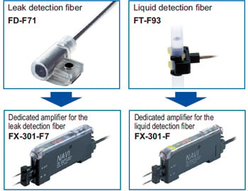
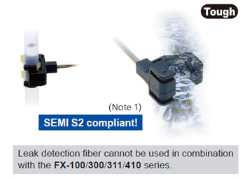
For use with leak detection or liquid detection fiber only
The FX-301-F7 (Note 1) dedicated for the leak detection fiber FD-F71 and the FX-301-F dedicated for the liquid detection fiber FT-F93 are available. Optimal setting is possible with easy operation.
Note: The FX-301-F can be also used by setting it to leak detection mode. However, the functions are different from the FX-301-F7 dedicated for the leak detection fiber, so it is recommended to use the FX-301-F7 when using the leak detection fiber.
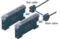
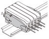
Easy maintenance, as main and sub units are identical
Both main and sub units utilize the same amplifier body. This feature allows for easy mounting in the side-by-side configuration. The main and sub unit functions are distinguished only by the proper use of 3-core main cable and the 1-core sub cable.
Moreover, by utilizing the same body for both main and sub units, inventory management and maintenance is simplified.
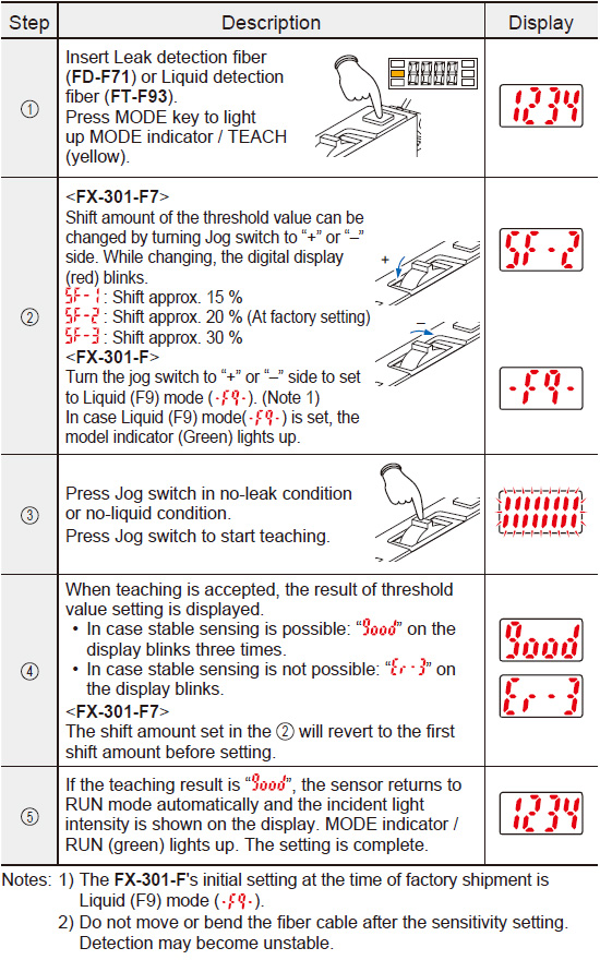
Sets the optimal threshold value [FX-301-F7]
Threshold value will be set automatically to -20 % of the incident light intensity during the teaching to steadily detect the leak. It is also possible to change the threshold value to -15 % or -30 %.
![Sets the optimal threshold value [FX-301-F7]](https://tp.industry.panasonic.com/hubfs/pid-corp/products/fasys/sensor/fiber/fx-301-f7/images/pic04.jpg)
Threshold follow-up function [FX-301-F7]
Incident light intensity is checked at regular time interval (10 min.), and threshold value is reset automatically.
*Function is set to OFF at the time of factory shipment.
![Threshold follow-up function [FX-301-F7]](https://tp.industry.panasonic.com/hubfs/pid-corp/products/fasys/sensor/fiber/fx-301-f7/images/pic05.jpg)
Flashing function incorporated
When the leak detection fiber is connected (F7 mode), if a leak is detected, you will recognize which fiber detects the leak at a single glance because the emitter will start flashing.
Long life and stable operational settings due to the newly developed emitting element
The newly developed “four-chemical emitting element” used for FX-301-F7 / FX-301-F can suppress the secular change of the light emitting element to minimum, allowing stable detection for long period of time.
Easy to operate with individual / collective teaching mode
Individual teaching mode (TEACH)
Optimal threshold value is set automatically on FX-301-F7 just by setting the MODE indicator to “TEACH” and pressing the jog switch.
(The threshold value is set after selecting the liquid detection fiber for FX-301-F.)
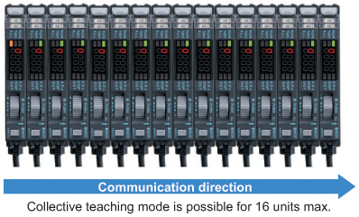
Collective teaching mode (ALL)
Teaching is performed collectively for all the connected amplifiers with an optical communication function when the MODE indicator is set to “ALL”. Each amplifier will be set with an optimal threshold value.
At the same time, other setting in the master unit will be copied to the slave unit.
Low profile liquid detection fiber with high chemical resistance
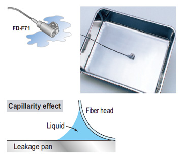
■Labor-saving design
・Because all you need to install is one screw, one-touch mounting of the fiber head is possible.
・Replacement parts even for resetting after a leak are unnecessary.
・Because the fiber head is simply designed, wiping off leaks is rendered easy.
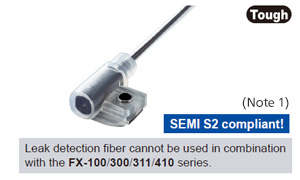
■Superb explosion resistance / chemical resistance
Explosion resistance is enhanced by adopting the fiber method (SEMI S2 compliant)(Note 1). The head unit made of fluorocarbon polymers also has superb chemical resistance.
(Note 1) :
The design takes into account the environmental testing required by SEMI S2.
To ensure that the final system complies with the standards, you must design and use it in accordance with relevant standards, regulations, and regulations.
■Stable detection performance
The unique effect of capillarity enables reliable detection of small leaks and viscous liquids.
■Compact, space-saving
This slim (10 mm 0.394 in) side-mounting fiber head is especially good for use in confined spaces.
■Amplifier built-in type photoelectric sensor is also line-up [EX-F70 / EX-F60]
Refer to "Leak Detection Sensor EX-F70/EX-F60" for details.
Stably detect the liquid inside the pipe!
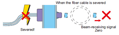
■Stable design that doesn’t permit liquid-absent or sensor errors
・When liquid is present, its effect on the lens causes light to focus and enter.
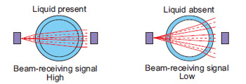
・When abnormalities such as a severed or removed fiber or a cutoff cable occur, light does not enter and the sensor will output the same as “liquid-absent”.
■Superior explosion resistance compatible to SEMI S2 (Note 1)
Because there is no electric circuitry in the fiber head, it boasts excellent explosion resistance.
(Note 1) :
The design takes into account the environmental testing required by SEMI S2.
To ensure that the final system complies with the standards, you must design and use it in accordance with relevant standards, regulations, and regulations.
■Easy to use and reliable detection
Even when the shape and thickness of the pipe vary, this fiber head uses a method where the beam axis follows the diameter of the pipe, and so when compared to conventional methods, the shape and thickness of the pipe have no influence over the performance of this fiber head.
■Reliable detection not affected by bubbles or droplets
Latest optical fiber techniques have solved problems caused by bubbles, droplets or liquid leakage that arise in conventional pipe-mountable fiber heads.
Order guide
Amplifiers
Quick-connection cable is not supplied with the amplifier. Please order it separately.
Type | Appearance | Model No. | Emitting element | Output | |
|---|---|---|---|---|---|
| Leak detection fiber only | NPN output |
| FX-301-F7 | Red LED | NPN open-collector transistor |
| PNP output | FX-301P-F7 | PNP open-collector transistor | |||
| Liquid detection fiber only | NPN output | FX-301-F | Red LED | NPN open-collector transistor | |
| PNP output | FX-301P-F | PNP open-collector transistor | |||

Quick-connection cables
Quick-connection cable is not supplied with the amplifier. Please order it separately.
| Type | Model No. | Description | |
|---|---|---|---|
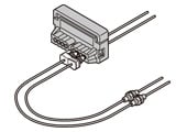
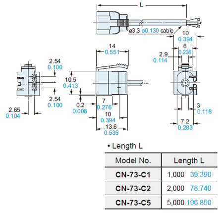
| Main cable (3-core) | CN-73-C1 | Length: 1 m 3.281 ft | 0.2 mm2 3-core cabtyre cable, with connector on one end Cable outer diameter: ø3.3 mm ø0.130 in |
| CN-73-C2 | Length: 2 m 6.562 ft | ||
| CN-73-C5 | Length: 5 m 16.404 ft | ||
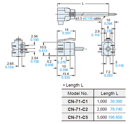
| Sub cable (1-core) | CN-71-C1 | Length: 1 m 3.281 ft | 0.2 mm2 1-core cabtyre cable, with connector on one end Cable outer diameter: ø3.3 mm ø0.130 in |
| CN-71-C2 | Length: 2 m 6.562 ft | ||
| CN-71-C5 | Length: 5 m 16.404 ft | ||
(Note):
The material of Quick-connection cable will be changed from production in March 2013, as soon as the previous ones are shipped out.
・Conductor cross-sectional area has been changed from 0.15mm2 to 0.2mm2.
・Sheath diameter has been changed from ø3.0mm to ø3.3mm.
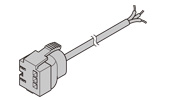
Main cable
CN-73-C□
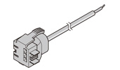
Sub cable
CN-71-C□
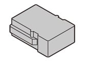
End plates
End plates are not supplied with the amplifier. Please order it separately when the amplifiers are mounted in cascade.
| Appearance | Model No. | Description |
|---|---|---|
| MS-DIN-E | When amplifiers are mounted in cascade, or when an amplifier moves depending on the way it is installed on a DIN rail, these end plates clamp amplifiers into place on both sides. Make sure to use end plates when cascading multiple amplifiers together. [2 pcs. per set] |
Fiber heads
| Designation | Shape of fiber head (mm in) | Model No. | Bending radius (mm) | Fiber cable length Free-cut | Description | Protection | Ambient temp. |
|---|---|---|---|---|---|---|---|
| Leak detection fiber | SEMI S2 compliant (Note) W20 × H30 × D10 W0.787 × H1.181 × D0.394
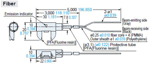
| [Tough] [Bending durability] FD-F71 | [R4] | Free-cut 5 m 16.405 ft | Liquid leak detection Leak absent: Beam received, Leak present: Beam not received Dedicated amplifier for the leak detection fiber : FX-301-F7 | IP67 | −20 to +60 °C −4 to +140 °F |
| Liquid detection fiber | SEMI S2 compliant (Note) W23 × H20 × D17 W0.906 × H0.787 × D0.669
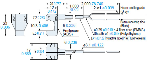
| [Tough] [Bending durability] FT-F93 | Protective tube R20 Fiber [R2] | Free-cut 2 m 6.562 ft | Applicable pipe diameter: Outer dia. ø3 to ø10 mm ø0.118 to ø0.394 in Transparent pipe PFA (fluorine resin) or equivalently transparent pipe, wall thickness 0.3 to 1.0 mm 0.012 to 0.039 in Liquid absent: Beam not received, Liquid present: Beam received) Dedicated amplifier for the liquid detection fiber : FX-301-F | IP40 | −40 to +60 °C −40 to +140 °F |


(Note) :
The design takes into account the environmental testing required by SEMI S2.
To ensure that the final system complies with the standards, you must design and use it in accordance with relevant standards, regulations, and regulations.
[Tough]:
Refers to a fiber which possesses both unbreakable (bending radius: R10 mm R0.394 in, reciprocating bending: 180°) and more flexible (bending radius: R4 mm R0.157 in or less) features.
[Bending durability]:
Refers to a fiber which possesses unbreakable bending-resistant feature (bending radius: R10 mm R0.394 in, reciprocating bending: 180°).
About the handling of the fiber cable length changed product
The type with fiber cable length changed is prepared as a semi-custom product with fast response.
Please contact the sales regarding the model name, standard price, and delivery.
• Applicable fiber cable length: Up to 25 m 82.021 ft, in 1 m 3.281 ft intervals.
• Applicable protective tube length: Up to 10 m 32.808 ft, in 0.5 m 1.641 ft intervals.
Accessories
FX-CT2 (Fiber cutter)
FX-AT4 (Attachment for φ1 mm φ0.039 in fiber, black)
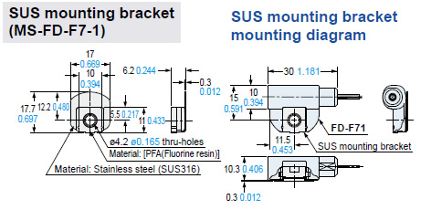
MS-FD-F7-1 (SUS mounting bracket for FD-F71)
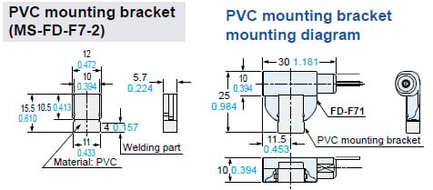
MS-FD-F7-2 (PVC mounting bracket for FD-F71)
FX-CT2
FX-AT4
MS-FD-F7-1
(SUS mounting bracket for FD-F71)

MS-FD-F7-2
(PVC mounting bracket for FD-F71)
Option
| Designation | Model No. | Description |
|---|---|---|
| Amplifier mounting bracket | MS-DIN-2 | Mounting bracket for amplifier |
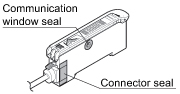
| Fiber sensor amplifier protection seal | FX-MB1 | 10 sets of 2 communication window seals and 1 connector seal Communication window seal: It prevents malfunction due to transmission signal from another amplifier, as well as, prevents effect on another amplifier. Connector seal: It prevents contact of any metal, etc., with the pins of the quickconnection cable. |
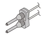
Amplifier mounting bracket
MS-DIN-2
Fiber sensor amplifier protection seal
FX-MB1
![]()
Specifications
| Type | For leak detection fiber | For liquid detection fiber | |
|---|---|---|---|
| Model No. | NPN output | FX-301-F7 | FX-301-F |
| PNP output | FX-301P-F7 | FX-301P-F | |
| Applicable fibers | FD-F71 | FT-F93 | |
| Supply voltage | 12 to 24 V DC ± 10 % Ripple P-P 10 % or less | ||
| Power consumption | Normal operation: 960 mW or less (Current consumption 40 mA or less at 24 V supply voltage) ECO mode: 600 mW or less (Current consumption 25 mA or less at 24 V supply voltage) | ||
| Output | <NPN output type> NPN open-collector transistor ・Maximum sink current: 100 mA (50 mA, if five, or more, amplifiers are connected in cascade.) ・Applied voltage: 30 V DC or less (between output and 0 V) ・Residual voltage: 1.5 V or less [at 100 mA (50 mA, if five, or more, amplifiers are connected in cascade.) sink current] <PNP output type> PNP open-collector transistor ・Maximum source current: 100 mA (50 mA, if five, or more, amplifiers are connected in cascade.) ・Applied voltage: 30 V DC or less (between output and +V) ・Residual voltage: 1.5 V or less [at 100 mA (50 mA, if five, or more, amplifiers are connected in cascade.) source current] | ||
| Output operation | OFF when leak is detected | Liquid setting (F9 mode): Using the jog switch, choose the signal OFF condition between absence of liquid and presence of liquid. Leak setting (F7 mode): OFF with detection of leak | |
| Short-circuit protection | Incorporated | ||
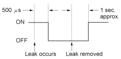
| Response time | 500 μs or less (Note 2) | 250 μs or less (Note 2) | |
| Sensitivity setting | Individual teaching / Collective teaching | ||
| Operation indicator | Orange LED (lights up when the output is ON) | ||
| Automatic follow-up function indicator | Green LED [lights up when automatic follow-up function is ON | - | |
| Model indicator | - | Green LED [lights up during liquid setting (F9 mode)] | |
| MODE indicator | RUN: Green LED, TEACH ・ ALL ・ ADJ ・ DISP ・ OUT: Yellow LED | ||
| Digital display | 4 digit red LED display | ||
| Fine sensitivity adjustment function | Incorporated | ||
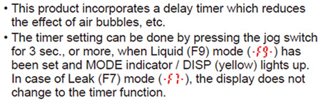
| Timer function | - | Delay timer [used only for liquid setting (F9 mode)] (Timer setting selectable from 10 ms, 100 ms, 1,000 ms, and none) | |
| Ambient temperature | 0 to +50 ℃ +32 to +122℉ (If 8 to 16 units are connected in cascade: 0 to +45 ℃ +32 to +113 ℉) (No dew condensation), Storage: -20 to +70 ℃ -4 to +158 ℉ | ||
| Ambient humidity | 35 to 85 % RH, Storage: 35 to 85 % RH | ||
| Ambient illuminance | Incandescent light: 3,000 lx at the light-receiving face | ||
| Voltage withstandability | 1,000 V AC for one min. between all supply terminals connected together and enclosure (Note 3) | ||
| Insulation resistance | 20 MΩ, or more, with 250 V DC megger between all supply terminals connected together and enclosure (Note 3) | ||
| Vibration resistance | 10 to 150 Hz frequency, 0.75 mm 0.030 in amplitude in X, Y and Z directions for two hours each | ||
| Shock resistance | 98 m/s2 acceleration (10 G approx.) in X, Y and Z directions for five times each | ||
| Emitting element | Red LED (Peak emission wavelength: 650 nm 0.026 mil, modulated) | ||
| Material | Enclosure: Heat-resistant ABS, Case cover: Polycarbonate, Switch: Acrylic | ||
| Connecting method | Connector (Note 4) | ||
| Cable length | Total length up to 100 m 328.084 ft is possible with 0.3 mm2, or more, cable. | ||
| Weight | Net weight: 20 g approx, Gross weight: 35 g approx. | ||
Note 1 :Where measurement conditions have not been specified precisely, the conditions used were an ambient temperature of +23 ℃ +73.4℉.
Note 2 :When detecting leak (output OFF) during leak setting (F7 mode), since the sensor flashes the emitted light, only the response action for turning the signal back to ON is delayed (1 sec. approx.).
Note 3 :The voltage withstandability and the insulation resistance values given in the above table are for the amplifier only.
Note 4 :The cable for amplifier connection is not supplied as an accessory. Make sure to use the optional quick-connection cable given below.
Main cable (3-core): CN-73-C1 (cable length 1 m 3.281 ft), CN-73-C2 (cable length 2 m 6.562 ft), CN-73-C5 (cable length 5 m 16.404 ft)
Sub cable (1-core): CN-71-C1 (cable length 1 m 3.281 ft), CN-71-C2 (cable length 2 m 6.562 ft), CN-71-C5 (cable length 5 m 16.404 ft)
Dimensions
- Unit: mm in
FX-301-(P)-F7
FX-301(P)-F
Amplifier
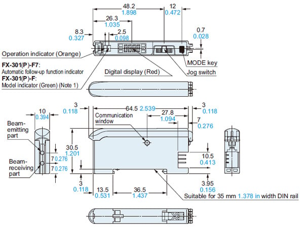
Note: Above figure is an external dimension drawing of the FX-301(P)-F7. Shape of the indicator for FX-301(P)-F is little different.
CN-73-C□
Main cable (Optional)
CN-71-C□
Sub cable (Optional)
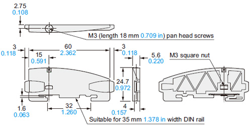
MS-DIN-2
Amplifier mounting bracket (Optional)
Material:Cold rolled carbon steel (SPCC)(Uni-chrome plated)
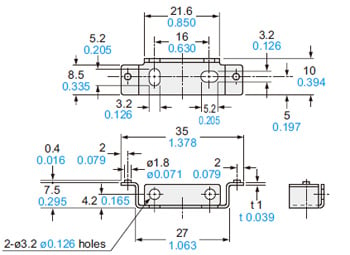
MS-DIN-E
End plates (Optional)
Material:Polycarbonate
FD-F71
Free-cut
<with FX-AT4>
FT-F93
Free-cut
<with FX-AT4>
I/O Circuit and Wiring diagrams
NPN output type
FX-301-F7
FX-301-F
I/O circuit diagram
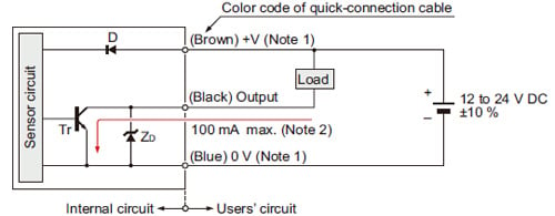
Notes:1) The quick-connection sub cable does not have +V (brown) and 0 V (blue). The power is supplied from the connector of the main cable.2) 50 mA max., if five amplifiers, or more, are connected in cascade.3) Never connect several amplifiers in series (AND).
Symbols・・・
D : Reverse supply polarity protection diode
ZD: Surge absorption zener diode
Tr: NPN output transistor
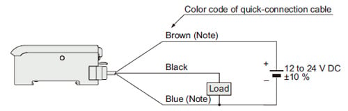
Wiring diagram
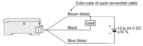
Note:The quick-connection sub cable does not have brown lead wire and blue lead wire. The power is supplied from the connector of the main cable.
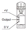
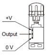
Terminal arrangement diagram
PNP output type
FX-301P-F7
FX-301P-F
I/O circuit diagram
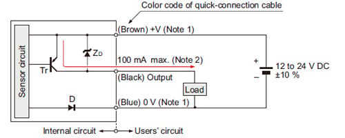
Notes:1) The quick-connection sub cable does not have +V (brown) and 0 V (blue). The power is supplied from the connector of the main cable.2) 50 mA max., if five amplifiers, or more, are connected in cascade.3) Never connect several amplifiers in series (AND).
Symbols・・・
D : Reverse supply polarity protection diode
ZD: Surge absorption zener diode
Tr: PNP output transistor
Wiring diagram
Note:The quick-connection sub cable does not have brown lead wire and blue lead wire. The power is supplied from the connector of the main cable.
Terminal arrangement diagram
Part description

[1]Operation indicator (Orange)・・・
Lights up when output is ON.
[2]FX-301-F7:Automatic follow-up function indicator (Green)・・・
Lights up when automatic follow-up function is ON.
FX-301-F:Model indicator (Green)・・・
Lights up during liquid setting (F9 mode).
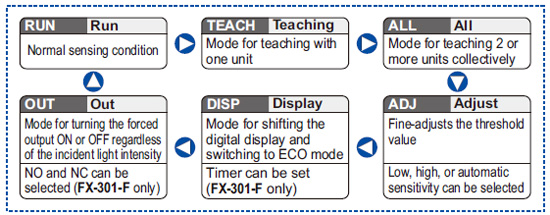
[3]MODE indicators・・・:
RUN (Green): Lights up during normal sensing operation.
TEACH (Yellow): Lights up when the individual teaching mode is selected.
ALL (Yellow): Lights up when the collective teaching mode is selected.
ADJ (Yellow): Lights up when the threshold value fine adjustment mode is selected or the sensitivity switching function is activated.
DISP (Yellow): Lights up when the digital display setting mode is selected or the timer function (FX-301-F only) is activated.
OUT (Yellow): Lights up when the forced output mode is selected or the NO / NC switching function is activated.
[4]Jog switch・・・
Moving this switch in the “+” or “–” direction, allows different items to be viewed for selection and pressing the switch then confirms the selected setting.
[5]MODE key・・・
This key is used to select operating modes and to cancel settings during the configuration process.
Setting items
Individual teaching mode
- When MODE indicator / TEACH (yellow) lights up, threshold value can be set on a single unit.
Timer function (FX-301-F only)
Time chart

Wiring
- Wiring tasks and expansion tasks must be performed with the power off.
- Verify that the supply voltage variation is within the rating.
- Take care that if a voltage exceeding the rated range is applied, or if an AC power supply is directly connected, the product may get burnt or damaged.
- In case noise generating equipment (switching regulator, inverter motor, etc.) is used in the vicinity of this product, connect the frame ground (F.G.) terminal of the equipment to an actual ground.
- If power is supplied from a commercial switching regulator, ensure that the frame ground (F.G.) terminal of the power supply is connected to an actual ground.
- Make sure to use an isolation transformer for the DC power supply. If an autotransformer (single winding transformer) is used, this product or the power supply may get damaged.
- When a surge occurs in the power used, absorb the surge with a surge absorber connected to the power source.
- Take care that short circuit of the load wrong wiring may burn or damage the product.
- Do not run the wires together with high-voltage lines or power lines or put them in the same raceway. This can cause malfunction due to induction.
- Make sure to use the optional quick-connection cable for the connection of the amplifier. Extension up to total 100 m 328.084 ft is possible with 0.3 mm2, or more, cable. However, in order to reduce noise, make the wiring as short as possible.
Others
- Do not use during the initial transient time (0.5 sec. approx.) after the power supply is switched on.
- Take care that the sensor is not directly exposed to fluorescent lamp from a rapid-starter lamp, a high frequency lighting device or sunlight etc., as it may affect the sensing performance.
- Do not use this sensor in places having excessive vapor, dust, etc., or where it may come in contact with corrosive gas.
- When the fiber head gets dusty or dirty etc. the sensitivity deteriorates. To keep stable detection, wipe the fiber head to remove dust or dirt etc. and carry out sensitivity teaching periodically.
- These sensors are only for indoor use.
- Take care that the product does not come in contact with oil, grease, organic solvents, such as thinner, etc., strong acid or alkaline.
- This sensor cannot be used in an environment containing inflammable or explosive gases.
- Never disassemble or modify the sensor.
- EEPROM is adopted to this product. It is not possible to conduct teaching 100 thousand times or more, because of the EEPROM's lifetime.