Basic Information
Slim body 13 mm 0.512 in
Maximum sensing height 540 mm 21.260 in


UL : Recognition
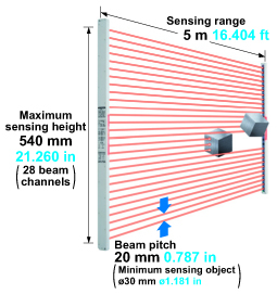
Maximum sensing height 540 mm 21.260 in (28 beam channels)
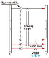
The thin resin case type area sensor has a sensing hight of 540 mm 21.260 in (28 beam channels), a beam pitch of 20 mm 0.787 in (minimum sensing object of ø30 mm ø1.181 in), and sensing range of 5 m 16.404 ft to meet a variety of needs.
Slim body of just 13 mm 0.512 in thick
The slim-bodied NA2-N series fits right in your equipment, since it is only 13 mm 0.512 in thick and 30 mm 1.181 in wide. It dose not get in the way of your access to the machine.

6 types of sensing height
In addition to the conventional 12, 16, and 20 beam channel types, this new lineup includes 8, 24, and 28 beam channel types. A wide model variation is provided with sensing heights from 540 mm 21.260 in (28 beam channels) to 140 mm 5.512 in (8 beam channels).
Globally usable
It conforms to the EMC Directive, EMC Regulation and obtains the UL Recognition.
Moreover, PNP output type which is much in demand in Europe is also available.
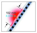
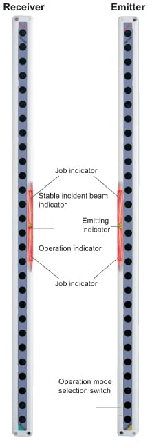
Clearly visible wide job indicator
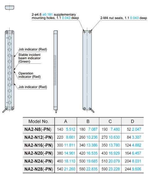
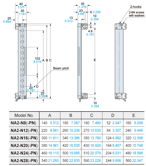
Both the receiver and the emitter feature job indicators, 102 mm 4.016 in wide, with red bright LEDs.
When the sensing output and the job indicator input are connected, the job indicator can be used as a large operation indicator.
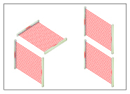
Interference prevention for parallel installation
By setting different emission frequencies for two sensors, mutual interference can be prevented. There is no problem even when the sensors are parallel installed for wide detections area coverage. Moreover, the set frequencies can be identified by how many times the emitting indicators is light up.
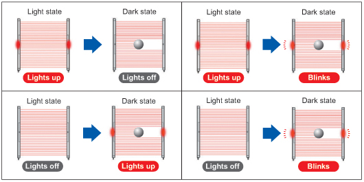
Selectable lighting pattern
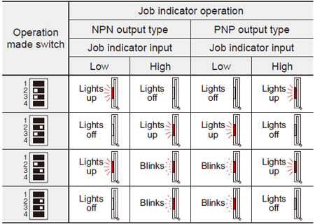
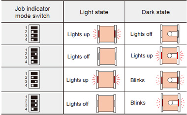
The operation of the job indicator can be selected using the operation mode selection switch.
Convenient test input (emission halt) function
Beam output can be stopped via the input of an external signal. This is an useful test input (emission halt) function when beginning operation.
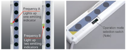
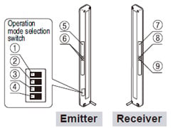
Note: The photo above shows an 8 beam channels type. The operation mode selection switch is equipped on the left side of the main body for models other than the 8 beam channels type.
Applications
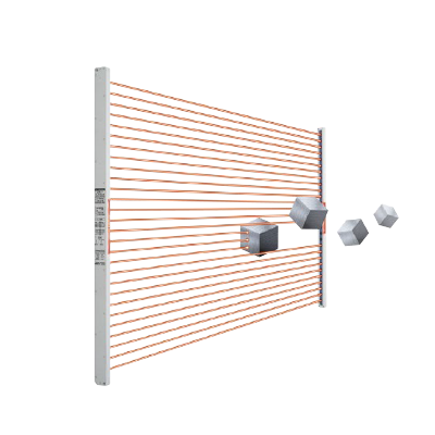
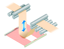
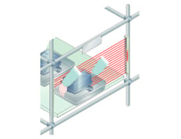
Detecting falling objects whose path is uncertain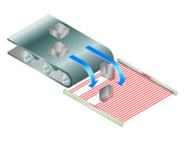
Order guide
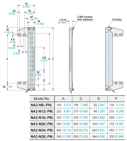
| Type | Appearance | Sensing range | Model No. (Note) | Number of beam channels | Sensing height (mm in) | Output |
|---|---|---|---|---|---|---|
| NPN output type |
| 5m 16.404 ft | NA2-N8 | 8 | 140 5.512 | NPN open-collector transistor |
| NA2-N12 | 12 | 220 8.661 | ||||
| NA2-N16 | 16 | 300 11.811 | ||||
| NA2-N20 | 20 | 380 14.961 | ||||
| NA2-N24 | 24 | 460 18.110 | ||||
| NA2-N28 | 28 | 540 21.260 | ||||
| PNP output type | NA2-N8-PN | 8 | 140 5.512 | PNP open-collector transistor | ||
| NA2-N12-PN | 12 | 220 8.661 | ||||
| NA2-N16-PN | 16 | 300 11.811 | ||||
| NA2-N20-PN | 20 | 380 14.961 | ||||
| NA2-N24-PN | 24 | 460 18.110 | ||||
| NA2-N28-PN | 28 | 540 21.260 |
Note :
The model No. with "P" shown on the label affixed to the product is the emitter, "D" shown on the label is the receiver.
5 m 16.404 ft cable length type
5 m 16.404 ft cable length type (standard: 3 m 9.843 ft ) is also availble for NPN output type.
When ordering this type, suffix "-C5" to the model No.
(e.g.) 5 m 16.404 ft cable length type of NA2-N8 is "NA2-N8-C5".
Option
| Designation | Model No. | Description | |
|---|---|---|---|
| Slit mask | OS-NA2-N8 | For 8 beam channels | The slit mask restrains the amount of beam emitted or received. 10 seal types in one set (5 sensor sets) Sensing range: 4 m 13.123 ft (slit on one side) 1.5 m 4.921 ft (slit on both sides) |
| OS-NA2-N12 | For 12 beam channels | ||
| OS-NA2-N16 | For 16 beam channels | ||
| OS-NA2-N20 | For 20 beam channels | ||
| OS-NA2-N24 | For 24 beam channels | ||
| OS-NA2-N28 | For 28 beam channels | ||
| Sensor mounting bracket (Note) | MS-NA1-1 | Four bracket set Eight M4 (length 18 mm 0.709 in) screws with washers (Four screws with washers are used), eight nuts, four hooks, four spacers and four M4 (length 15 mm 0.591 in) screws with washers are attached. (Spacers are not attached with MS-NA1-1. M4 (length 15 mm 0.591 in) screws with washers are not used for NA2-N series.) | |
| MS-NA2-1 | |||
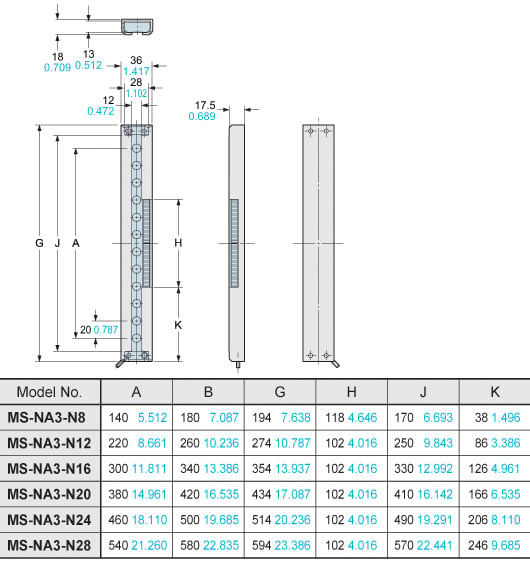
| Sensor supporting bracket | MS-NA3-N8 | For 8 beam channels | Supports the body of the sensor when used in an environment with strong vibration. Two bracket set |
| MS-NA3-N12 | For 12 beam channels | ||
| MS-NA3-N16 | For 16 beam channels | ||
| MS-NA3-N20 | For 20 beam channels | ||
| MS-NA3-N24 | For 24 beam channels | ||
| MS-NA3-N28 | For 28 beam channels | ||
Note:
Do not fix the sensor mounting bracket on the front surface of the sensor.
Slit mask
OS-NA2-N□
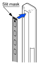
The slit mask restricts the amount of beam emitted or received and is used to reduce interference between neighboring sensors.It is also used in cases when the beam intensity is too strong penetrating through the sensing object.Remove the cover (name plate) from the front of the sensor and replace it with the slit mask. The sensing range is reduced when the slit mask is used.
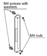
Sensor mounting bracket
MS-NA1-1
M4 screws with washers, nuts, and hooks are attached.
MS-NA2-1
M4 screws with washers, nuts, hooks and spacers are attached.
Sensor supporting bracket
MS-NA3-N□
Dimensions
- Unit: mm in
NA2-N□ NA2-N□-PN
Sensor
Emitter
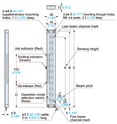
Note:Located on the right side in case of NA2-N8(-PN).
Receiver
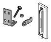
MS-NA1-1
Sensor mounting bracket (Optional)
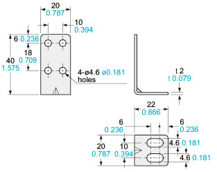
Material:Cold rolled carbon steel (SPCC)(Uni-chrome plated)Four bracket set[Eight M4 (length 18 mm0.709 in) screws with washers (Four screws with washers are used), eight nuts, four hooks, and four M4 (length 15 mm0.591 in) screws with washers are attached.M4 (length 15 mm0.591 in) screws with washers are not used for NA2-N series.]
Assembly dimensions
Mounting drawing with the receiver
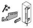
MS-NA2-1
Sensor mounting bracket (Optional)
Material:Cold rolled carbon steel (SPCC)(Uni-chrome plated)[Eight M4 (length 18 mm0.709 in) screws with washers (Four screws with washers are used), eight nuts, four hooks, four spacers, and four M4 (length 15 mm0.591 in) screws with washers are attached.M4 (length 15 mm0.591 in) screws with washers are not used for NA2-N series.]
Assembly dimensions
Mounting drawing with the receiver
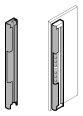
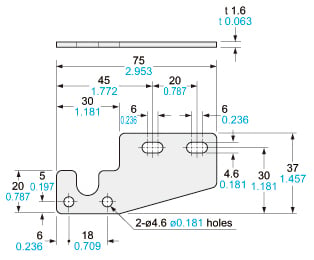
MS-NA3-N□
Sensor supporting bracket (Optional)
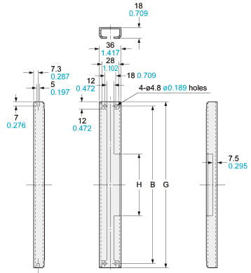
Material:Aluminum (Black ALMITE)Two bracket setNote:The sensor supporting bracket can be used for both the emitter and the receiver.
Assembly dimensions
Mounting drawing with the receiver
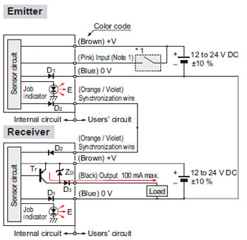
I/O Circuit and Wiring diagrams
NPN output type
I/O circuit diagram
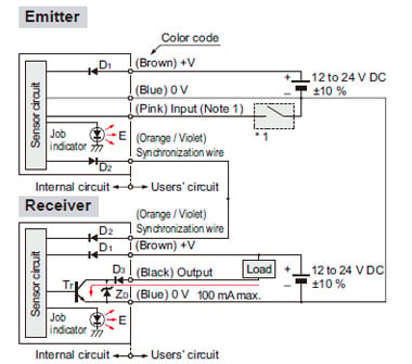
Notes:
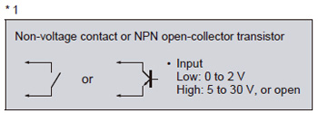
1) Input (pink) is the job indicator input when No. 4 of the operation mode switch on the emitter is set to the OFF side, and it is the test input (emission halt input) when the switch is set to the ON side.
2) In order to use the job indicator as a large operation indicator, connect the input (pink) of the emitter to the output (black) of the receiver.
3) When the test input (emission halt input) is set, the job indicator does not light up or blink.
Symbols・・・
D1: Reverse supply polarity protection diode
D2: Reverse current protection diode
D3: Reverse output polarity protection diode
ZD: Surge absorption zener diode
Tr: NPN output transistor
E : Job indicator
Wiring diagram
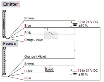
Note:
Refer to “CAUTIONS FOR PROPER USE” for job indicator operation or test input (emission halt input) operation.
PNP output type
I/O circuit diagram
Notes:
1) Input (pink) is the job indicator input when No. 4 of the operation mode switch on the emitter is set to the OFF side, and it is the test input (emission halt input) when the switch is set to the ON side.
2) In order to use the job indicator as a large operation indicator, connect the input (pink) of the emitter to the output (black) of the receiver.
3) When the test input (emission halt input) is set, the job indicator does not light up or blink.
Symbols・・・
D1: Reverse supply polarity protection diode
D2: Reverse current protection diode
D3: Reverse output polarity protection diode
ZD: Surge absorption zener diode
Tr: PNP output transistor
E : Job indicator
Wiring diagram
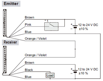
Note:
Refer to “CAUTIONS FOR PROPER USE” for job indicator operation or test input (emission halt input) operation.
Sensing characteristics
*TYPICAL
Correlation between setting distance and excess gain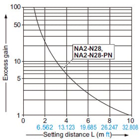
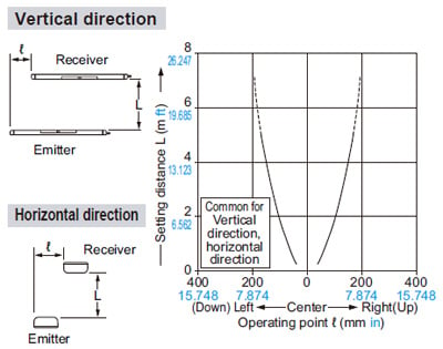
Parallel deviation (All models)
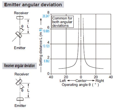
Angular deviation (All models)
Job indicator operation selection
- The operation of the job indicator can be selected with job indicator mode switch.
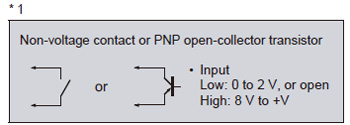
Job indicator input signal condition
| Type | Signal | Signal condition |
|---|---|---|
| NPN output | Low | 0 to 2 V |
| High | 5 to 30 V, or open (Note) | |
| PNP output | Low | 0 to 2 V, or open (Note) |
| High | 8 V to +V |
Note: Insulate the wire if it is kept open.
Mounting
(Purchase the screws and nuts separately.)
- Use M4 screws with washers and M4 nuts. The tightening torque should be 0.5 N·m or less. During mounting, do not apply any bending or twisting force to the sensor.
Functional description
| Description | Function | |||
|---|---|---|---|---|
| Emitter | ① | Emission frequency selection switch |
| |
| ② | Job indicator mode switch |
| ||
| ③ |
| |||
| ④ | Job indicator / Test input (emission halt input) selection switch |
| ||
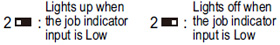
| ⑤ | Job indicator (Red LED) | Lights up, blinks or lights off when the job indicator input is applied, selected by operation mode switch. | ||
| ⑥ | Emitting indicator (Green LED × 2) | Light up during emission; one LED lights up for Frequency A setting, both LEDs light up for Frequency B setting. | ||
| Receiver | ⑦ | Job indicator (Red LED) | Lights up, blinks or lights off when the job indicator input is applied, selected by operation mode switch. | |
| ⑧ | Stable incident beam indicator (Green LED) | Lights up when all beam channels are stably received. | When an excess current flows through the output, the stable incident beam indicator and the operation indicator on the receiver blink simultaneously due to the operation of the short-circuit protection circuit. | |
| ⑨ | Operation indicator (Red LED) | Lights up when one or more beam channels are interrupted. | ||


To use job indicator as large operation indicator
- The job indicators can be used as large operation indicators by setting No. 4 of the operation mode switch to the OFF side and connecting the input (pink) of the emitter to the output (black) of the receiver.
Note: In order to use the job indicators as large operation indicators, make sure to set No. 4 of the operation mode switch to the OFF side. If it is set to the ON side, the job indicator does not light up or blink.
Orientation
- The emitter and the receiver must face each other correctly. If they are set upside down, the sensor does not work.
Test input (emission halt) function
Operation mode switch setting
| OFF | ON |
|---|---|
 |  |
- The emission is stopped when No. 4 of the operation mode switch is set to the ON side and the input (pink) of the emitter is made High (PNP output type: Low).
Since the output can be turned ON / OFF without the sensing object, this function is useful for start-up inspection. If the output follows the application / withdrawal of the test input (emission halt input), the sensor operation is normal, else it is abnormal.
Time chart
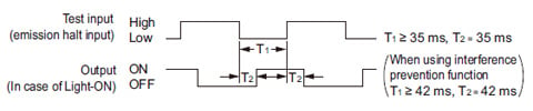
Notes:
1) When the test input (emission halt) function is set, the job indicator (red) does not light up or blink.
2) When emission is stopped during the test input (emission halt) function, the emitter’s emitting indicator (green) does not light up.
Interference prevention function
- By setting different emission frequencies, two units of NA2-N series can be mounted close together, as shown in the figure below. The emission frequency can be checked by the number of LEDs lighting up in the emitting indicator on the emitter.
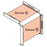
| Operation mode switch | Emitting indicator (Emitter) | |
|---|---|---|
| Sensor Ⓐ |
|
|
| Sensor Ⓑ |
|
|


Wiring
- Make sure that the power supply is off while wiring.
- Verify that the supply voltage variation is within the rating.
- If power is supplied from a commercial switching regulator, ensure that the frame ground (F.G.) terminal of the power supply is connected to an actual ground.
- In case noise generating equipment (switching regulator, inverter motor, etc.) is used in the vicinity of this sensor, connect the frame ground. (F.G.) terminal of the equipment to an actual ground.
- Do not run the wires together with high-voltage lines or power lines or put them in the same raceway. This can cause malfunction due to induction.
Use conditions to comply with CE Marking
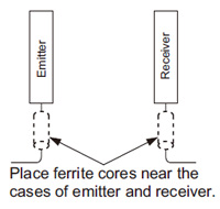
- Following work must be done in case of using this product as a CE marking (European standard EMC Directire) conforming product.
Place ferrite core at the sensor cable.
Prepare 2 pcs. of the following recommended ferrite core (or an equivalent product.)
<Recommended product>
- ESD-SR-110 [NEC TOKIN Corporation]
- ZCAT1730-0730A(-BK) [TDK Corporation]
- E04SR170730A
[SEIWA ELECTRIC MFG. CO., LTD.]
Others
- Do not use during the initial transient time (500 ms) after the power supply is switched on.
- Avoid dust, dirt and steam.
- Take care that the sensor does not come in direct contact with water, oil, grease, or organic solvents, such as, thinner, etc.
- Take care that the sensor is not directly exposed to fluorescent light from a rapid-starter lamp or a high frequency lighting device, as it may affect the sensing performance.