------------------------------ Tab1 showing ------------------------------
Basic Information

Single axis type
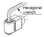
Direct installation using a hexagonal wrench


UL : Recognition
Features
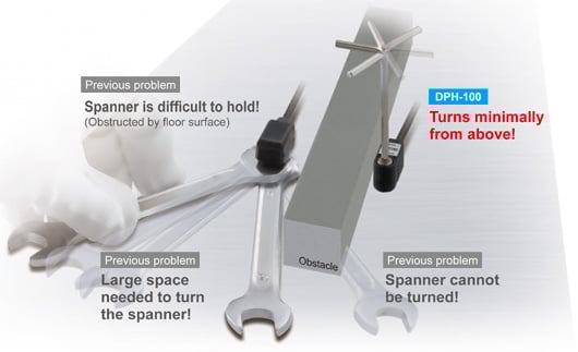
Breakthrough construction
Obstructions can be avoided and installation from above can be done much more easily using a hexagonal wrench. This also eliminates wasted installation space and contributes to a smaller installation footprint.
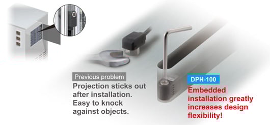
Flexible design! Sensor heads can be embedded
Because the bolts can be turned from directly above, embedding the sensor heads into narrow spaces is possible. In addition, the flat installation leaves no worries for danger of objects striking against the sensor and damaging it.
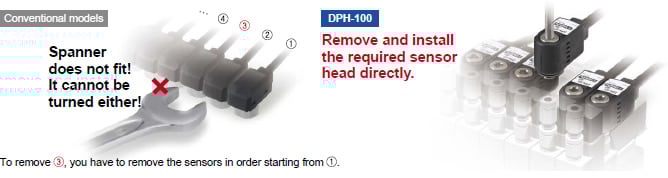
Quick maintenance
During maintenance, the sensor head needed to be removed can be easily removed from directly above.
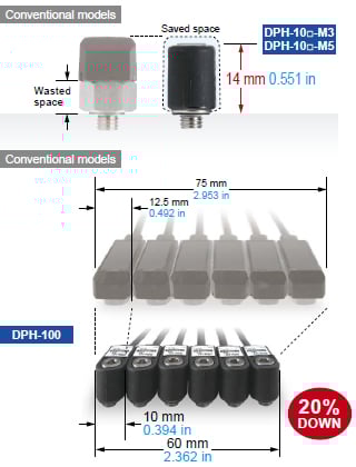
Mounting space-saving
Space saving during installation.
Because the dead zone caused by the nut is eliminated, the narrowed-down thickness after installation contributes to space saving.
Easy adjustment
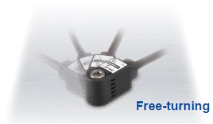
Sensor heads can be turned after installation
After installation, you can alter the cable direction with the pressure port still secured in place. In addition, the cable does not get twisted during installation.
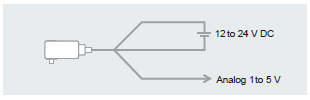
Independent use of sensor head possible
Separate analog voltage output for each sensor head
The analog voltage output from the sensor head can be picked up directly.
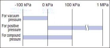
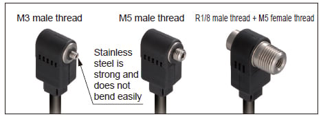
Sensor head line-up
3 types of pressure range
Stainless steel pressure ports come in 3 shapes.
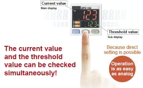
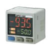
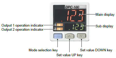
Dual display + Direct setting
Equipped with a 30 mm 1.181 in square compact-sized dual display.
"Current value" and "Threshold value" can be checked at the same time.
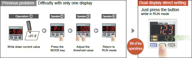
The threshold value can be changed in RUN mode directly.
High-speed response time at 500 μs
Reduced tact time. Response time contributes to even greater productivity.
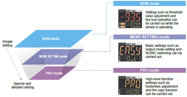
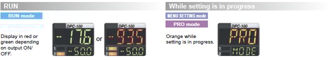
The controller's setting operation mode has a 3-level configuration to suit the frequency of use
The setting levels are clearly separated into "RUN mode" for operation settings that are carried out daily, "MENU SETTING mode" for basic settings, and "PRO mode" for special and detailed setting. These make setting operations easy to understand and easy to carry out.
3-color display lets you view the controller status at a glance
The main display color switches between green and red in accordance with the ON / OFF status of output during RUN mode. In addition, the display always appears orange while setting is in progress, so that the status of the controller can be viewed at a glance.
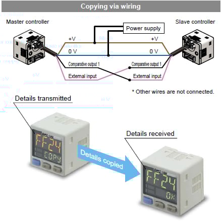
Copy function reduces man-hours and human error
Controllers can be connected to a master controller one by one, and a copy of the setting details for the master controller can be transmitted as data to the slave controllers. If making the same settings for multiple controllers, this prevents setting errors from occurring with the other controllers and also reduces the number of changes required to instruction manuals when equipment designs are changed.
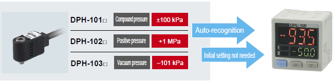
Sensor head auto-recognition
The controller will automatically recognize sensor heads when they are connected, even for sensor heads with different rated pressure ranges. There is no need to use the controller to change settings.
1 model to suit a wide variety of applications [DPC-100 original functions]
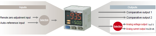
Equipped with independent two output and three output modes
Equipped with two independent comparative outputs, and separate sensing modes can be selected for each of them.
Two comparative outputs are provided, so that one of the outputs can be used as a warning output. In addition, if an output is not being used, it can be disabled.
Equipped with auto-reference / remote zero-adjustment functions, More precise pressure management is possible with a minimum of effort
If the reference pressure of the device changes, the autoreference function partially shift the comparative output judgment level by the amount that the reference pressure shifts, and the remote zero-adjustment function can reset the display value to zero via external input. These functions are ideal for places where the reference pressure fluctuates wildly, or where fine settings are desired.
Sub display can be customized
The sub display can be set to indicate any other desired values or letters apart from the threshold value. This eliminates the need for tasks such as affixing a label to the device to indicate the normal pressure value.
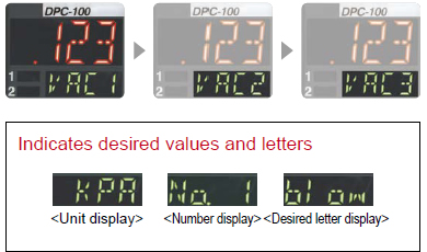
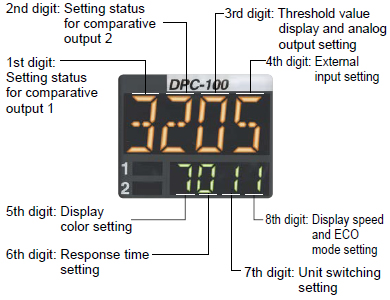
Setting details can be understood at a glance
The DPC-100 setting details appear in the digital display.
Because the settings are in numeric form that can be easily understood, it is useful for times such as when receiving technical support by telephone.
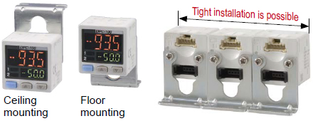
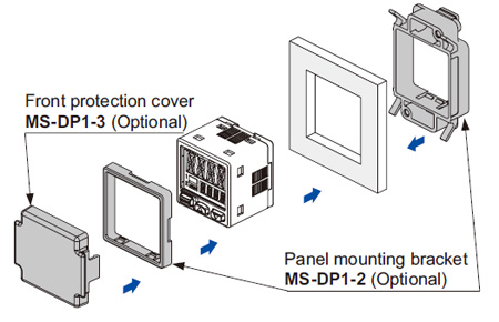
Tight installation to panels is possible
An exclusive mounting bracket (MS-DP1-2) that is suitable for 1 to 6 mm 0.039 to 0.236 in panel thickness is available.

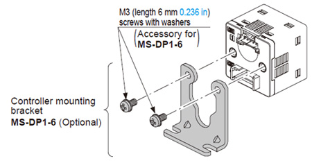
An exclusive mounting bracket (MS-DP1-6) that supports tight installation is available
Space saving can also be obtained if an L-shaped mounting bracket is used.
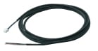
Power supply cable can be connected with one-touch connection
The accessory connector attached cable (2 m 6.562 ft) can be connected easily with one-touch connection.
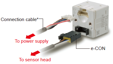
* Options: 5 m16.404 fttype is also available.
Types without connector attached cable are also available [DPC-10□-J]
Commercially-available connectors can be used for cable connections. Only the required length of cable needs to be used, which contributes to a reduced amount of wastage for unneeded cable.
------------------------------ Tab2 showing ------------------------------
Order guide
Product configuration

Sensor heads
| Type | Appearance | Rated pressure range | Model No. | Pressure port | Applicable fluid | |
|---|---|---|---|---|---|---|
| Compound pressure |
| –100.0 to +100.0 kPa | DPH-101 | R1/8 male thread + M5 female thread | Air, non-corrosive gas | |
| DPH-101-M3 | M3 male thread | |||||
| DPH-101-M5 | M5 male thread | |||||
| Bending-resistant cable | DPH-101-R | R1/8 male thread + M5 female thread | ||||
| DPH-101-M3-R | M3 male thread | |||||
| DPH-101-M5-R | M5 male thread | |||||
| Positive pressure | 0 to +1.000 MPa | DPH-102(Note) | R1/8 male thread + M5 female thread | |||
| DPH-102-M5 | M5 male thread | |||||
Bending-resistant cable | DPH-102-M5-R | M5 male thread | ||||
| Vacuum pressure | 0 to –101.0 kPa | DPH-103 | R1/8 male thread + M5 female thread | |||
| DPH-103-M3 | M3 male thread | |||||
| DPH-103-M5 | M5 male thread | |||||
| Bending-resistant cable | DPH-103-R | R1/8 male thread + M5 female thread | ||||
| DPH-103-M3-R | M3 male thread | |||||
| DPH-103-M5-R | M5 male thread | |||||

(Note):
The bending-resistant cable type of DPH-102 is not available.
5 m 16.404 ft cable length type
5 m 16.404 ft cable length type (standard: 2 m 6.562 ft) is also available. When ordering this type, suffix "-C5" to the Model No. (e.g.) 5 m 16.404 ft cable length type of DPH-103-M5-R is "DPH-103-M5-R-C5"
Controllers
| Appearance | Rated pressure range | Model No. | Comparative output |
|---|---|---|---|
* CN-66A-C2(Connector attached cable 2 m 6.562 ft) is attached. | Compound pressure: –100.0 to +100.0 kPa Positive pressure: 0 to +1.000 MPa Vacuum pressure: 0 to –101.0 kPa | DPC-101 | NPN open-collector transistor |
| DPC-101-P | PNP open-collector transistor |
Type without connector attached cable
Type without connector attached cable CN-66A-C2 is available. When ordering this type, suffix "-J" to the Model No. (e.g) Type without connector attached cable of DPC-101-P is "DPC-101-P-J".
Accessory
CN-66A-C2
(Connector attached cable 2 m 6.562 ft)
------------------------------ Tab3 showing ------------------------------
Option
| Designation | Model No. | Description | |
|---|---|---|---|
| Sensor head connector (e-CON) | CN-EP2(Note 1) [5 pcs. per set] | Connector for connecting sensor head controller | |
| Connector attached cable | CN-66A-C2(Note 2) | Length 2 m 6.562 ft | Connector for controller power supply I/O cable. 0.2 mm2 6-core oil-resistant cabtyre cable with connector |
| CN-66A-C5 | Length 5 m 16.404 ft | ||
| Power supply connector | CN-66A [5 pcs. per set] | Connector for controller power supply I/O cable. | |
| Controller mounting bracket | MS-DP1-6 | Allows sensors to be installed on the wall. Multiple sensors can also be mounted closely. | |
| Panel mounting bracket | MS-DP1-2 | Allows installation to panels with thickness of 1 to 6 mm 0.039 to 0.236 in. Multiple sensors can also be mounted closely. | |
| Front protection cover | MS-DP1-3 | Protects the adjustment surfaces of controllers. (Can be attached when using the panel mounting bracket) | |
Note 1:One is attached to each sensor head according to standard.
Note 2:The connector attached cable CN-66A-C2 is supplied with the controller according to standard.
Sensor head connector(e-CON)
CN-EP2
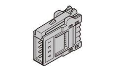
Note:One is attached to each sensor head according to standard.
Connector attached cable
CN-66A-C2
CN-66A-C5
Note:The connector attached cable CN-66A-C2 is supplied with the controller according to standard.
Power supply connector
CN-66A
Controller mounting bracket
MS-DP1-6
Panel mounting bracket, Front protection cover
MS-DP1-2
MS-DP1-3
Recommended e-CON
Model No.: 1473562-4 (Manufactured by Tyco Electronics Japan G.K.)
Note: Contact the manufacturer for details of the recommended products.
Recommended power supply connector
Contact: SPHD-001T-P0.5, Housing: PAP-06V-S (Manufactured by J.S.T. Mfg.Co., Ltd.)
Note: Contact the manufacturer for details of the recommended products.
Recommended crimping tool
Model No.: YC-610R (Manufactured by J.S.T. Mfg. Co., Ltd.)
Note: Contact the manufacturer for details of the recommended products.
------------------------------ Tab4 showing ------------------------------
------------------------------ Tab5 showing ------------------------------
Dimensions
- Unit: mm in
DPH-10□(-R)
Sensor head
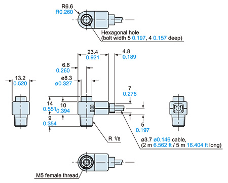
DPH-10□-M3(-R) DPH-10□-M5(-R)
Sensor head
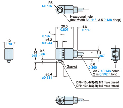
•Length L
| Model No. | A |
|---|---|
| DPH-10□-M3(-R) | 3 0.118 |
| DPH-10□-M5(-R) | 3.5 0.138 |
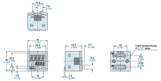
DPC-101(-P)
Controller
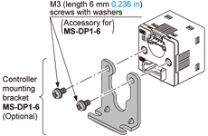
MS-DP1-6
Controller mounting bracket (Optional)
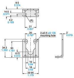
Assembly dimensions
Material:Cold rolled carbon steel (SPCC) (Uni-chrome plated)Two M3 (length 6 mm0.236 in) screws with washers are attached.
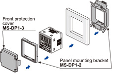
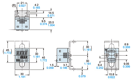
MS-DP1-2 MS-DP1-3
Panel mounting bracket (Optional), Front protection cover (Optional)
Assembly dimensions
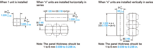
Mounting drawing with DPC-101
Vertical mounting
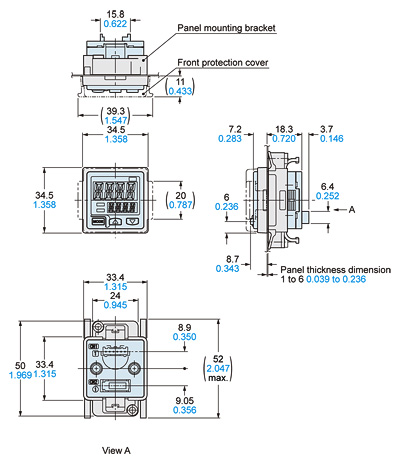
Material:Polyacetal (Panel mounting bracket)Polycarbonate (Front protection cover)
Horizontal mounting
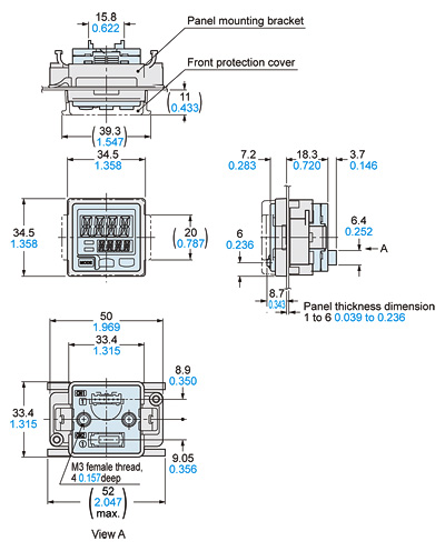
Panel cut-out dimensions
CN-66A-C2 CN-66A-C5
Connector attached cable (Optional, CN-66A-C2 is attached to the controller)
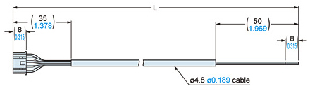
•Length L
| Model No. | A |
|---|---|
| CN-66A-C2 | 2,000 78.740 |
| CN-66A-C5 | 5,000 196.850 |
------------------------------ Tab6 showing ------------------------------
I/O Circuit and Wiring diagrams
DPC-101
NPN output type
I/O circuit diagram
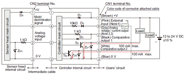
Notes:
1)Select and use the auto-reference function and remote zero-adjustment function.
2)Set the output load resistance during analog current output to 250 Ω (max.)
3)Note that a voltage of 5 V or higher is generated during analog current output.
Symbols・・・
D1 to D4 : Reverse supply polarity protection diode
ZD1 to ZD3 : Surge absorption zener diode
Tr1, Tr2 : NPN output transistor
*1

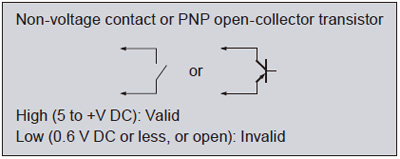
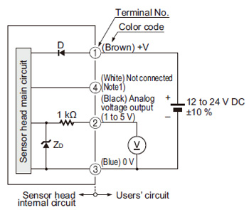
For independent use of sensor head
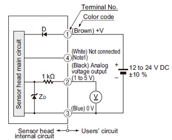
Notes:
1)In case the sensor head is used independently, insulate the white lead wire (terminal No.4) and keep it open.
2)When the sensor head is used independently, devices connected to the analog output must have an input impedance set at 50 kΩ or more.
Symbols・・・
D : Reverse supply polarity protection diode
ZD: Surge absorption zener diode
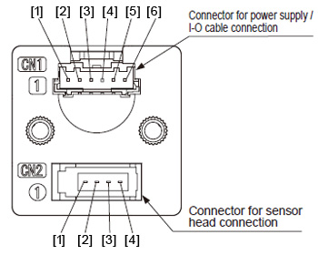
Terminal arrangement diagram
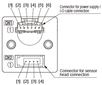
Connector for power supply / I-O cable (CN1)
[1] +V
[2] Analog voltage / current output
[3] 0 V
[4] Comparative output 1
[5] Comparative output 2
[5] External input (auto-reference function / remote zero-adjustment function)
Connector for sensor head (CN2)
[1] Sensor head power supply
[2] Analog voltage input
[3] 0 V
[4] Model discrimination signal
DPC-101-P
PNP output type
I/O circuit diagram
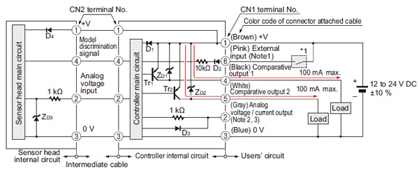
Notes:
1)Select and use the auto-reference function and remote zero-adjustment function.
2)Set the output load resistance during analog current output to 250 Ω (max.)
3)Note that a voltage of +5 V or higher is generated during analog current output.
Symbols・・・
D1 to D4 : Reverse supply polarity protection diode
ZD1 to ZD3 : Surge absorption zener diode
Tr1, Tr2: PNP output transistor
*1
For independent use of sensor head
Notes:
1)In case the sensor head is used independently, insulate the white lead wire (terminal No.4) and keep it open.
2)When the sensor head is used independently, devices connected to the analog output must have an input impedance set at 50 kΩ or more.
Symbols・・・
D : Reverse supply polarity protection diode
ZD: Surge absorption zener diode
Terminal arrangement diagram
Connector for power supply / I-O cable (CN1)
[1] +V
[2] Analog voltage / current output
[3] 0 V
[4] Comparative output 1
[5] Comparative output 2
[6] External input (auto-reference function / remote zero-adjustment function)
Connector for sensor head (CN2)
[1] Sensor head power supply
[2] Analog voltage input
[3] 0 V
[4] Model discrimination signal
------------------------------ Tab7 showing ------------------------------
Cautions For Use
- Never use this product as a sensing device for personnel protection.
- In case of using sensing devices for personnel protection, use products which meet laws and standards, such as OSHA, ANSI or IEC etc., for personnel protection applicable in each region or country.
- The DPH-100 series is designed for use with air and non-corrosive gas. It cannot be used with liquid or corrosive and inflammable gases.
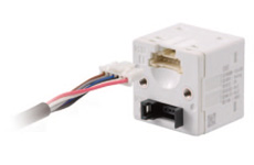
Part description
Wiring
- Make sure that the power supply is off while wiring.
- Verify that the supply voltage variation is within the rating.
- If power is supplied from a commercial switching regulator, ensure that the frame ground (F.G.) terminal of the power supply is connected to an actual ground.
- In case noise generating equipment (switching regulator, inverter motor, etc.) is used in the vicinity of this sensor, connect the frame ground (F.G.) terminal of the equipment to an actual ground.
- Do not run the wires together with high-voltage lines or power lines or put them in the same raceway. This can cause malfunction due to induction.
- Incorrect wiring will cause problems with operation.
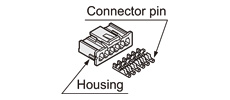
Connection
Do not apply stress directly to the connection cable leader or to the connector.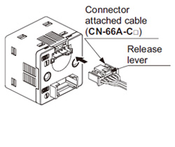
<Connector of connector attached cable>
Housing: PAP-06V-S
[Manufactured by J.S.T Mfg. Co. Ltd.]
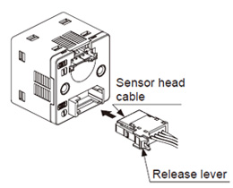
<Connector of sensor head cable>
e-CON: 1473562-4
[Manufactured by Tyco Electronics Japan G.K.]
Mounting
- When tightening the controller to the controller mounting bracket MS-DP1-6 (optional), use a tightening torque of 0.5 N·m or less.
- The MS-DP1-2 panel mounting bracket (optional) and the MS-DP1-3 front protection cover (optional) are also available.
Piping
・
Use a hexagonal wrench to install sensor head. For the tightening torque, refer to the following diagram. If excessive tightening torque is applied, the pressure port of the sensor head or the M5 male screw of the commercial coupling will get damaged. In case of R1/8 male thread type, wrap sealing tape around the coupler when connecting to prevent leakage.
| Pressure port | Hexagonal wrench (bolt width) | Tightening torque |
|---|---|---|
| R1/8 male thread | 5 mm 0.197 in | 9.8 N·m or less |
| M3 male thread | 3 mm 0.118 in | 0.8 N·m or less |
| M5 male thread | 1.5 N·m or less |
Others
- Use within the rated pressure range.
- Do not apply pressure exceeding the pressure withstandability value. The diaphragm will get damaged and correct operation shall not be maintained.
- Do not use during the initial transient time (controller: 0.5 sec. approx, sensor head: 50 ms approx.) after the power supply is switched on.
- Avoid dust, dirt, and steam.
- Take care that the sensor does not come in direct contact with water, oil, grease, or organic solvents, such as, thinner, etc.
- Do not insert wires, etc., into the pressure port. The diaphragm will get damaged and correct operation shall not be maintained.
- Do not operate the keys with pointed or sharp objects.
RUN mode
- This is the normal operating mode.
| Setting item | Description |
|---|---|
| Threshold value setting | The threshold values for ON / OFF operation can be changed directly by pressing the increment key (UP) and the decrement key (DOWN). |
| Zero-adjustment function | This forces the pressure value display to be reset to zero when the pressure port is open on the atmospheric pressure side. |
| Key lock function | Stops key operations from being accepted. |
| Peak hold / bottom hold function | Displays the peak value and bottom value for fluctuating pressure. The peak value appears in the main display, and the bottom value appears in the sub display. |
MENU SETTING mode
- If the mode selection key is pressed and held for 2 sec. in RUN mode, the mode will switch to MENU SETTING mode.
- If the mode selection key is pressed while a setting is being made, the mode will switch to RUN mode. In this case, the settings that have been changed will be entered.
| Setting item | Description |
|---|---|
| Comparative output 1 output mode setting | Sets the output mode for comparative output 1. |
| Comparative output 2 output mode setting | Sets the output mode for comparative output 2. |
| Analog voltage / current output selection | Selects analog voltage output or analog current output. |
| External input selection | Selects auto-reference function, or remote zero-adjustment function. |
| NO / NC selection | Normally open (NO) or normally closed (NC) can be selected. |
| Response time setting | Sets the response time. The response time can be selected from 0.5 ms, 1 ms, 2.5 ms, 5 ms, 10 ms, 25 ms, 50 ms, 100 ms, 250 ms, 500 ms, 1,000 ms and 5,000 ms. |
| Display color switching for main display | Allows the color for the main display to be changed. The colors can be set to “red / green” or “green / red” to correspond to ON / OFF output, or it can be fixed at “red” or “green” all the time. |
| Unit switching | Pressure unit can be changed. |
PRO mode
- If the mode selection key is pressed and held for 5 sec. in RUN mode, the mode will switch to PRO mode.
- If the mode selection key is pressed while a setting is being made, the mode will switch to RUN mode. In this case, the settings that have been changed will be entered.
| Setting item | Description |
|---|---|
| Sub display switching | Changes the information in the sub display during RUN mode operation to the current pressure unit, number and desired alphanumeric display. |
| Display refresh rate switching | Changes the display refresh rate for the pressure value displayed in the main display. |
| Hysteresis fix value switching | Sets the hysteresis for EASY mode and window comparator mode. (8 steps) |
| Linked display color switching | Allows the display color for the main display to be switched in line with the output operation for comparative output 1 or comparative output 2. |
| External input relation selection | The setting contents set at the external input selection in MENU SETTING mode can be shifted to correspond to either comparative output 1, 2 or 1 / 2. |
| ECO mode setting | Allows power consumption to be reduced by dimming the display or turning it off. |
| Setting check code | Allows the setting details to be checked via codes. (Refer to below) |
| Setting copy mode | Allows the setting details for the master controller to be copied to slave controllers. |
| Reset setting | Resets the settings to the factory settings. |
Table of codes
| Code | 1st digit | 2nd digit | 3rd digit | 4th digit | ||||
|---|---|---|---|---|---|---|---|---|
| Comparative output 1 output mode | NO / NC selection | Comparative output 2 output mode | NO / NC selection | Analog output | Threshold display | External input | ||
| 0 | EASY | NO | OFF | – | Analog voltage output | Threshold value 1 | OFF | – |
| 1 | NC | EASY | NO | Threshold value 2 | Auto-reference | Comparative output 1 | ||
| 2 | Hysteresis | NO | NC | Threshold value 3 | Comparative output 2 | |||
| 3 | NC | Hysteresis | NO | Threshold value 4 | Comparative output 1 / 2 | |||
| 4 | Window comparator | NO | NC | Analog current output | Threshold value 1 | Remote zero-adjustment | Comparative output 1 | |
| 5 | NC | Window comparator | NO | Threshold value 2 | Comparative output 2 | |||
| 6 | – | – | NC | Threshold value 3 | Comparative output 1 / 2 | |||
| 7 | – | – | – | – | Threshold value 4 | – | – | |
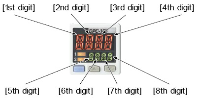
| Code | 5th digit | 6th digit | 7th digit | 8th digit | ||
|---|---|---|---|---|---|---|
| Displayed color of the main display | Displayed color relation | Response time | Unit selection (Note) | Display refresh rate | Eco mode | |
| 0 | Red when ON | Comparative output 1 | 0.5 ms | MPa | 250 ms | OFF |
| 1 | Comparative output 2 | 1 ms | kPa | STD | ||
| 2 | Green when ON | Comparative output 1 | 2.5 ms | kgf/cm2 | FULL | |
| 3 | Comparative output 2 | 5 ms | bar | 500 ms | OFF | |
| 4 | Always red | Comparative output 1 | 10 ms | psi | STD | |
| 5 | Comparative output 2 | 25 ms | mmHg | FULL | ||
| 6 | Always green | Comparative output 1 | 50 ms | inHg | 1,000 ms | OFF |
| 7 | Comparative output 2 | 100 ms | – | STD | ||
| 8 | – | – | 250 ms | – | FULL | |
| 9 | – | – | 500 ms | – | – | – |
| A | – | – | 1,000 ms | – | – | – |
| B | – | – | 5,000 ms | – | – | – |
Note:When positive pressure type of the pressure sensor head is connected to the controller for use inside Japan, “0” (MPa) or “1” (kPa) is displayed. When compound pressure type or vacuum pressure type is connected, only “1” (kPa) is displayed.