Discontinued Products

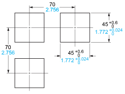
Dimensions
- Unit: mm in
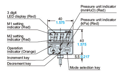
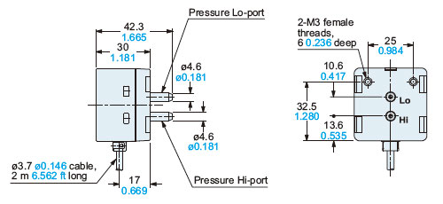
DP-M□
sensor
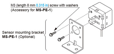
MS-PE-1
Sensor mounting bracket (Optional)
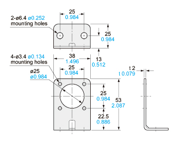
Material:Cold rolled carbon steel (SPCC)Two M3 (length 8 mm0.315 in) screws with washers are attached.
Assembly dimensions
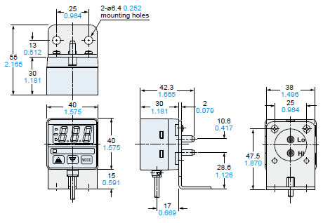
MS-PE-2 MS-PE-3
Panel mounting bracket, front protection cover(Optional)
Assembly dimensions

Material:Polycarbonate (Front protection cover)Nylon 6, Polyacetal (Panel mounting bracket)
Panel cut-out dimensions
Note:The panel thickness should be 1 to 3.2 mm0.039 to 0.126 in.
I/O Circuit and Wiring diagrams
I/O circuit diagram
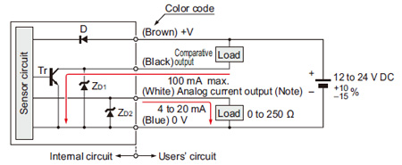
Note:
The analog current output is equipped only with the DP-M2A.
The analog current output of DP-M2A does not incorporate a short-circuit protection circuit. Do not connect it directly to a power supply or a capacitive load.
Symbols・・・
D: Reverse supply polarity protection diode
ZD1, ZD2: Surge absorption zener diode
Tr: NPN output transistor
Wiring diagram
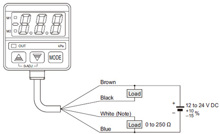
Note:
The white lead wire is equipped only with the DP-M2A.
Mounting
- The displayed value may vary by 1 digit (0.01 kPa.D {1 mmH2O.D}) maximum depending on whether the sensor is installed vertically or horizontally.
- A sensor mounting bracket MS-PE-1 (optional) may be used. When mounting the sensor with the sensor mounting bracket, the tightening torque should be 0.5 N·m or less.
Conditions in use for CE conformity
Conditions
- The DP-M series is a CE conformity product complying with EMC Directive. The harmonized standard with regard to immunity that applies to this product is EN 61000-6-2 and the following condition must be met to conform to that standard.
Operation
- If setting is impossible even with pressing the MODE key, verify whether the key-protect function is enabled. Please note that pressing down on the MODE key for an extended moment (for 4 sec. or more) will enable the key-protect function as soon as the key is released. The key-protect function is set when the display shows [ON] and is released when the display shows [OFF].
- If using the window comparator mode, lower threshold value (M1) and upper threshold value (M2) should be set with a difference of 3 digits (0.03 kPa.D {3 mmH2O.D}) or more. No output will be possible with a 0 to 2 digits difference.
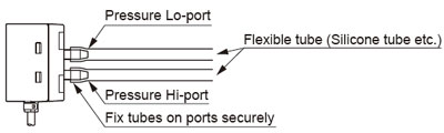
Piping
Apply higher pressure to the Hi-port and lower pressure to the Lo-port.
Recommended tube
- Use flexible tubes (silicone tube etc.) that can fit the pressure ports, ø4.6 mm ø0.181 in in diameter. The tubes should cover more than half the length of the pressure ports.
Notes:
1)TYGON is registered trademarks of Saint-Gobain K. K.
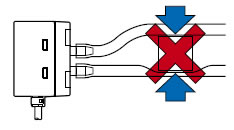
2)Ensure that excessive pressure is not applied to the pressure ports. Since this sensor is designed for detecting small pressures, if excessive pressure or shock is applied to the pressure ports, the diaphragm (pressure sensing device) in the sensor may get damaged.
3)Please do not compress the tube. If the tube is compressed, pressure exceeding the rated value may be generated, damaging the diaphragm (pressure sensing device).
Wiring
- The analog current output of DP-M2A does not incorporate a short-circuit protection circuit. Do not connect it directly to a power supply or a capacitive load.
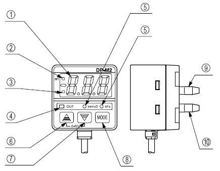
Functional description
| Description | Function | ||
|---|---|---|---|
| (1) | 3 digit LED display (Red) | The measured differential pressure level, setting values, error codes, and key protection sign are displayed. | |
| (2) | M1 setting indicator (Red) | Blinks in the lower threshold value (M1) setting mode. | |
| (3) | M2 setting indicator (Red) | Blinks in the upper threshold value (M2) setting mode. | |
| (4) | Operation indicator (Orange) | Lights up when the comparative output is ON. | |
| (5) | Pressure unit indicator (mmH2O, kPa) (Red) | ・ The indicator of the selected unit lights up during the sensing mode. ・ Both indicators light off during the initial setting mode and during an error occurrence. ・ The indicator of the selected unit blinks during the upper and lower threshold value setting mode. | |
| (6) | Increment key
| ・ The settable digit is shifted cyclically at every press of the key during the initial setting mode. ・ Pressing the key increases the set value, in the upper and lower threshold value setting mode. | During the sensing mode, pressing both switches calibrates the sensor into atmospheric zero. |
| (7) | Decrement key
| ・ The set condition changes at every press of the key during the initial setting mode. ・ Pressing the key decreases the set value, in the upper and lower threshold value setting mode. | |
| (8) | Mode selection key
| ・ Three modes, the sensing mode, the lower threshold value (M1) setting mode, and the upper threshold value (M2) setting mode, are cyclically selected at every press of the key. ・ During the sensing mode, pressing the key for 4 sec., or more, can make the key protection either effective or ineffective. ・ Holding the increment key and simultaneously pressing the mode selection key brings the sensor from the sensing mode to the initial setting mode. | |
| (9) | Pressure Lo-port | Lower pressure should be applied. | |
| (10) | Pressure Hi-port | Higher pressure should be applied. | |


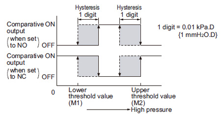
Output mode and output operation
Hysteresis mode (H) (M1 < M2)
- The lower threshold value and the upper threshold value establish the hysteresis of the comparative output.
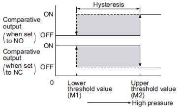
Window comparator mode (C) (M1 < M2)
- The comparative outputs can be made ON or OFF by a pressure within the limits set by the upper and the lower threshold levels.
・
When operating in window comparator mode (C) lower threshold value (M1) and upper threshold value (M2) should be set with a difference of 3 digits (0.03 kPa.D {3 mmH2O.D}) or more.
Others
- Use within the rated pressure range.
- Do not apply pressure exceeding the pressure withstandability value. The diaphragm will get damaged and correct operation shall not be maintained.
- Do not use during the initial transient time (0.5 sec.) after the power supply is switched on.
- Do not insert wires, etc., into the pressure port. The diaphragm will get damaged and correct operation shall not be maintained.
- Do not operate the keys with pointed or sharp objects.