------------------------------ Tab1 showing ------------------------------
Basic Information

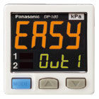
Dual 3-color display makes operation easier!


UL : Recognition
Features
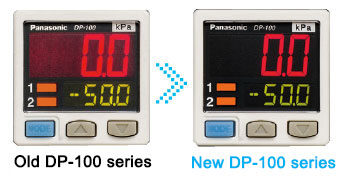
"Superior visibility": Improved visibility in Digital Display
Improvements to the digital display deliver a wide viewing angle along with increased clarity. The display pressure range and set pressure range have also been increased.
"Long-distance transmission of analog output": Addition of analog current output capability to multifunctional models
Users can now select either voltage output or current output as analog output according to their application.
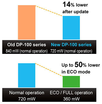
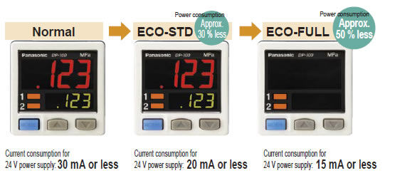
"Reduced environmental impact": 14% lower power consumption (during normal operation)
Thanks to a redesign of its circuitry, power consumption of the low-power-consumption DP-100 series during normal operation has been reduced by 14%. The display is shut off entirely during ECO / FULL mode operation for power savings of up to 50% compared to normal operation, and display brightness is lowered during ECO / STD mode operation for power savings of up to 30% compared to normal operation.
Enhanced power circuitry
Addition of a reverse polarity protection circuit to the transistor output circuit
To prevent from breakage due to miswiring.
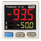
"Current value" and "threshold value" can be checked at the same time!
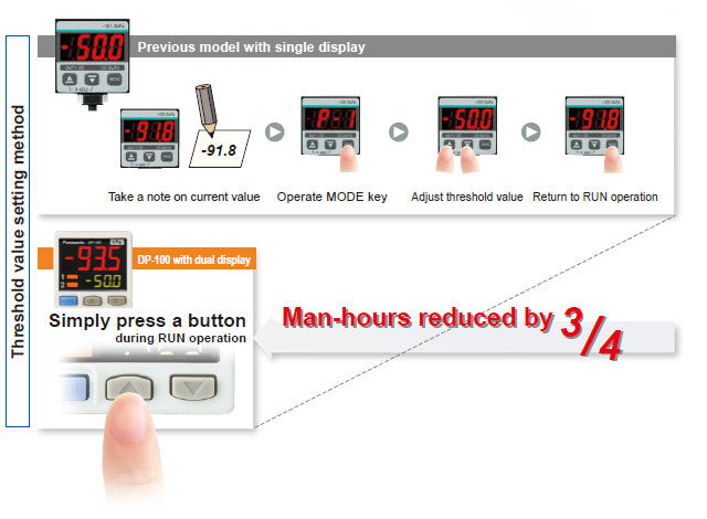
Dual display allows direct setting of threshold value
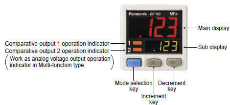
Equipped with a 30 mm 1.181 in square compact-sized dual display. The current value and the threshold value can be checked at the same time, so the threshold value can be set and checked smoothly without switching to another screen mode. ON / OFF operations still continue while the threshold values are being set, so setting to the same sensitivity as dial control-type sensors is possible. Key lock function is equipped as well.
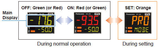
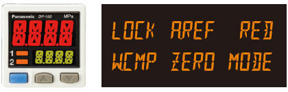
3-color display (Red, Green, Orange)
The main display changes color in line with changes in the status of output ON / OFF operation, and it also changes color while setting is in progress. The sensor status can therefore be understood easily, and operating errors can be reduced.
Readable digital display
12 segments are used and an alphanumeric display has been adopted. This improves visual checking of letters and numbers.
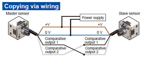
Copy function reduces man-hours and human error
Sensors can be connected to a master sensor one by one, and a copy of the setting details for the master sensor can be transmitted as data to other sensors. If making the same settings for multiple sensors, this prevents setting errors among other sensors and in addition, when machinery design are changed, there would be less change in work orders.
Setting details can be copied.
Note:Settings cannot be copied from the new version (Ver. 2) to the old version.However, settings can be copied from the old version to the new version (Ver. 2).
The sensor’s setting operation mode has a 3-level configuration to suit the frequency of use.
The setting levels are clearly separated into "RUN mode" for operation settings that are carried out daily, "MENU SETTING mode" for basic settings, and "PRO mode" for special and detailed setting. These make setting operations easy to understand and easy to carry out.
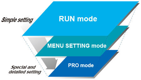
RUN mode
Settings such as threshold value adjustment and key lock operation can be carried out while the sensor is operating.
MENU SETTING mode
Basic settings such as output mode setting and NO / NC switching can be carried out.
PRO mode
High-level function settings such as hysteresis adjustment and the copy function can be carried out.

Equipped with independent dual output [Standard type]
Equipped with two independent comparative outputs, and separate sensing modes can be selected for each of them. Since there are two comparative outputs, one of the comparative outputs can even be used for alarm output. In addition, output, which is not being used, can be disabled.
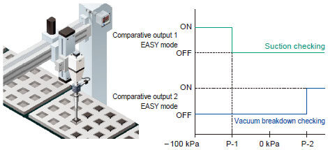
Vacuum breakdown can also be notified during suction applications!
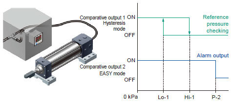
Reference pressure alarm output is possible during reference pressure checking!
Three output modes are suitable for a wide range of applications
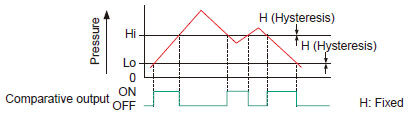
1. EASY mode
This mode is used for comparative output ON / OFF control.
Notes:1) Hysteresis can be fixed to one of eight different levels.2) "P-1" appears in the sub display for comparative output 1, and "P-2" appears for comparative output 2.
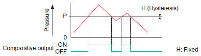
2. Hysteresis mode
This mode is used for setting comparative output hysteresis to the desired level and for carrying out ON / OFF control.
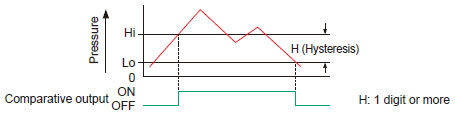
Notes: "Hi-1" or "Lo-1" appears in the sub display for comparative output 1, and "Hi-2" or "Lo-2" appears for comparative output 2.
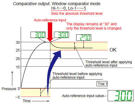
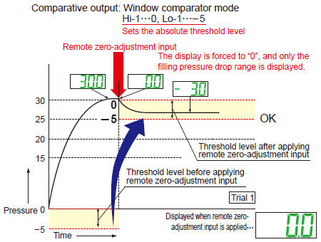
3. Window comparator mode
This mode is used for setting comparative output ON and OFF at pressures within the setting range.
Notes:1) Hysteresis can be fixed to one of eight different levels.2) "Hi-1" or "Lo-1" appears in the sub display for comparative output 1, and "Hi-2" or "Lo-2" appears for comparative output 2.
Possible to switch over analog output and external input [Multi-function type]
Multi-function type that enables the selection of analog output (voltage/current) or external input (auto-reference/
remote zero-adjustment) is available. It complies a wide range of applications.
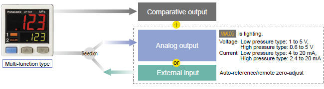
Equipped with auto-reference / remote zero-adjustment functions, More precise pressure management is achieved with a minimum of effort [Multi-function type]
If the reference pressure of the device changes, two functions are selectable. One is auto-reference function, which partially shift the comparative output judgment level by the amount that the reference pressure shifts. The other is remote zero-adjustment function, which can reset the display value to zero via external input. These functions are ideal for places where the reference pressure fluctuates wildly, or where fine settings are required.
Without auto-reference and remote zero-adjustment functions
Because the threshold level is fixed for conventional pressure sensors, changes in the reference pressure result in wrong decisions.
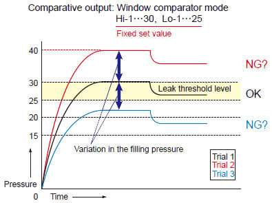
With auto-reference function applied
When auto-reference input is applied, the reference pressure "30" is added to the threshold level. If the reference pressure changes to "20" or "40", the auto-reference input compensates for this every time by changing the threshold level, so any variation in the filling pressure can be ignored.
With remote zero-adjustment function applied
When remote zero-adjustment input is applied, the reference pressure is forced to "0". If the reference pressure changes to "20" or "40", the remote zero-adjustment input adjusts the reference pressure to "0" every time the reference pressure changes, so any variation in the filling pressure can be ignored.
Sub display can be customized
The sub display can be set to indicate any other desired values or letters apart from the threshold value. This eliminates the need for tasks such as affixing a label to the device to indicate the normal pressure value.
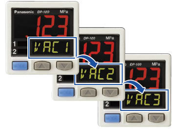
Setting details can be recognized at a glance
The DP-100 setting details appear in the digital display. Because the settings are in numeric form that can be easily understood, it is useful such as when receiving technical support by telephone.
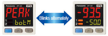
Peak hold and Bottom hold functions
The peak values and bottom values for fluctuating pressures can be displayed using the dual display.
Energy-saving design! Equipped with an ECO mode
This mode lowers the display luminance to cut power consumption by approximately 30 %. The displays can also be turned off completely to achieve a power saving of approximately 50 %.
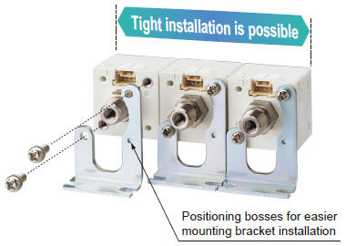
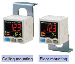
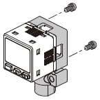
Tight installation to panels is possible
An exclusive mounting bracket that is suitable for 1 to 6 mm 0.039 to 0.236 in panel thickness is available.
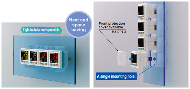
An exclusive mounting bracket that supports tight installation is available
Space savings can also be achieved even when an L-shaped mounting bracket is used.
・MS-DP1-1
・MS-DP1-5
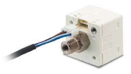
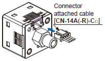
Cable can be connected with one-touch
Connector attached cable (2m 6.562 ft), as an accessory, can be connected easily with one-touch connection.
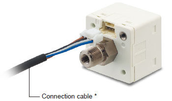
* Options: 1 m3.281 ft/ 3m9.843 ft/ 5m16.404 ft types are also available.
Types without connector attached cable are also available [DP-10□-J]
Commercially-available connectors can be used for cable connections. Cables in required length can be used, so this contributes to reduction in waste of unwanted cables.

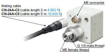
M8 plug-in connector types are also available (Only for Europe) [DP-11□-E-P-J]
Short pressure port type is lightweight and takes up little space [DP-10□-M]
Compact size with a depth of only 30 mm 1.181 in, so that it can easily fit into narrow spaces.
Further, 10 g lighter than standard types. This reduces the loads on movable parts such as robot arms.
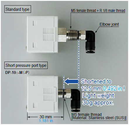
* The illustration shows connection using an elbow joint. The elbow joint is sold separately.
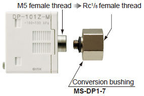
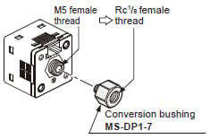
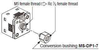
Rc1/8 conversion bushing is available. Compatible with conventional model
[For short pressure port type]
By equipping the push-in converter with DP-10□-M(-P), pressure port can be converted from M5 female thread to Rc1/8 female thread. Bore diameter conversion to the DP2 / DP3 series is possible.
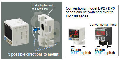
Flat installation on the wall by shifting the direction of the pressure port
[For short pressure port type]
By mounting the flat attachment to DP-10□-M(-P), pressure port and cable can now be pulled out in downward, left or right directions. Flat mounting on surfaces such as the wall is made possible.
| Model No. | Pressure port |
|---|---|
| MS-DP1-FM | M5 female thread |
| MS-DP1-FR | Rc1/8 female thread |
| MS-DP1-FN | NPT1/8 female thread |
| MS-DP1-FE | G1/8 female thread |
------------------------------ Tab2 showing ------------------------------
------------------------------ Tab3 showing ------------------------------
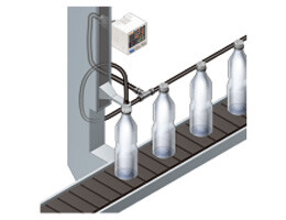
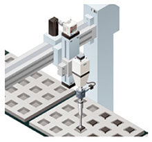
Applications
Confirming suction of electronic component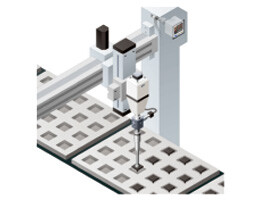

------------------------------ Tab4 showing ------------------------------
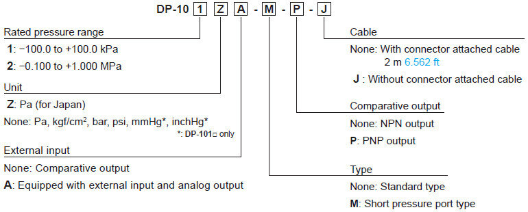
Order guide
Model No.
Standard pressure port type
| Type | Rated pressure range | Model No. | Pressure port | Comparative output | |||
|---|---|---|---|---|---|---|---|
| Asia | Standard | For low pressure | -100.0 to +100.0kPa | DP-101 | M5 female thread + R 1/8 male thread | NPN open-collector transistor | |
| For high pressure | -0.100 to +1.000MPa | DP-102 | |||||
| Multi-function | For low pressure | -100.0 to +100.0kPa | DP-101A | ||||
| For high pressure | -0.100 to +1.000MPa | DP-102A | |||||
| Europe | Standard | For low pressure | -100.0 to +100.0kPa | DP-101-E-P | M5 female thread + G 1/8 male thread | PNP open-collector transistor | |
| For high pressure | -0.100 to +1.000MPa | DP-102-E-P | |||||
| Multi-function | For low pressure | -100.0 to +100.0kPa | DP-101A-E-P | ||||
| For high pressure | -0.100 to +1.000MPa | DP-102A-E-P | |||||
| M8 plug-in connector type | Standard | For low pressure | -100.0 to +100.0kPa | DP-111-E-P-J | M5 female thread + G 1/8 male thread | PNP open-collector transistor | |
| For high pressure | -0.100 to +1.000MPa | DP-112-E-P-J | |||||
| Multi-function | For low pressure | -100.0 to +100.0kPa | DP-111A-E-P-J | ||||
| For high pressure | -0.100 to +1.000MPa | DP-112A-E-P-J | |||||
| North America | Standard | For low pressure | -100.0 to +100.0kPa | DP-101-N | M5 female thread + NPT 1/8 male thread | NPN open-collector transistor | |
| DP-101-N-P | PNP open-collector transistor | ||||||
| For high pressure | -0.100 to +1.000MPa | DP-102-N | NPN open-collector transistor | ||||
| DP-102-N-P | PNP open-collector transistor | ||||||
| Multi-function | For low pressure | -100.0 to +100.0kPa | DP-101A-N | NPN open-collector transistor | |||
| DP-101A-N-P | PNP open-collector transistor | ||||||
| For high pressure | -0.100 to +1.000MPa | DP-102A-N | NPN open-collector transistor | ||||
| DP-102A-N-P | PNP open-collector transistor | ||||||
Short pressure port type
| Type | Rated pressure range | Model No. | Pressure port | Comparative output | ||
|---|---|---|---|---|---|---|
| Asia | Standard | For low pressure | -100.0 to +100.0kPa | DP-101-M | M5 female thread | NPN open-collector transistor |
| DP-101-M-P | PNP open-collector transistor | |||||
| For high pressure | -0.100 to +1.000MPa | DP-102-M | NPN open-collector transistor | |||
| DP-102-M-P | PNP open-collector transistor | |||||
| Multi-function | For low pressure | -100.0 to +100.0kPa | DP-101A-M | NPN open-collector transistor | ||
| DP-101A-M-P | PNP open-collector transistor | |||||
| For high pressure | -0.100 to +1.000MPa | DP-102A-M | NPN open-collector transistor | |||
| DP-102A-M-P | PNP open-collector transistor | |||||
Type without connector attached cable
Type without connector attached cable CN-14A-C2 is available.
When ordering this type, suffix "-J" to the Model No. (Excluding M8 plug-in connector type and short pressure port type)
(e.g.) Type without connector attached cable of DP-101-N is "DP-101-N-J"
Accessory
CN-14A-C2
(Connector attached cable 2 m 6.562 ft)
------------------------------ Tab5 showing ------------------------------
Option
| Designation | Model No. | Description | |
|---|---|---|---|
| Connector attached cable | CN-14A-C1 | Length: 1m 3.281 ft | 0.2mm2 4-core cabtyre cable with connector on one end Cable outer diameter: ø3.7mm ø0.146 in |
| CN-14A-C2 (Note) | Length: 2m 6.562 ft | ||
| CN-14A-C3 | Length: 3m 9.843 ft | ||
| CN-14A-C5 | Length: 5m 16.404 ft | ||
| Connector attached cable (Bending-resistant cable) | CN-14A-R-C1 | Length: 1m 3.281 ft | 0.2mm2 4-core bending-resistant cabtyre cable with connector on one end Cable outer diameter: ø3.7mm ø0.146 in |
| CN-14A-R-C2 | Length: 2m 6.562 ft | ||
| CN-14A-R-C3 | Length: 3m 9.843 ft | ||
| CN-14A-R-C5 | Length: 5m 16.404 ft | ||
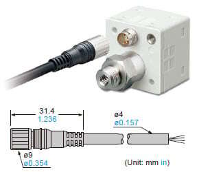
| M8 connector attached cable | CN-24A-C2 | Length: 2m 6.562 ft | For M8 plug-in connector type The connector on one end Cable outer diameter: ø4 mm ø0.157 in |
| CN-24A-C5 | Length: 5m 16.404 ft | ||
| Connector | CN-14A | Set of 10 housings and 40 contacts | |
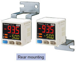
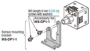
| Sensor mounting bracket | MS-DP1-1 | Allows sensors to be installed on the flooring or ceiling. Multiple sensors can also be mounted closely. | |
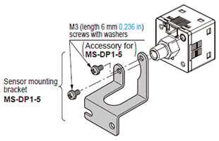
| MS-DP1-5 | Allows sensors to be installed on the wall. Multiple sensors can also be mounted closely. | ||
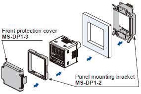
| Panel mounting bracket | MS-DP1-2 | Allows installation to panels with thickness of 1 to 6 mm 0.039 to 0.236 in. Multiple sensors can also be mounted closely. | |
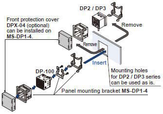
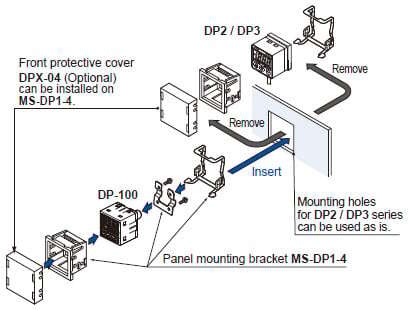
| MS-DP1-4 | Allows replacement from DP2 / DP3 series to DP-100 series. For newly designed set-up, please use panel mounting bracket MS-DP1-2 for panel mounting. | ||
| Front protection cover | MS-DP1-3 | Protects the adjustment surfaces of sensors. (Can be attached when using the panel mounting bracket MS-DP1-2) | |
| Front protection cover (For standard type) | DPX-04 | Protects the adjustment surfaces of sensors. (Can be attached when using the panel mounting bracket MS-DP1-4) | |
| Conversion bushing | MS-DP1-7 | By equipping with DP-10□-M(-P), pressure port can be converted to Rc1/8 female thread. Replacement from DP2 / DP3 series is possible. | |
| Flat attachment | MS-DP1-FM | M5 female thread | For DP-10□-M(-P). Pressure port and cable can now be pulled out in downward, left or right directions. Flat mounting on surfaces such as the wall is made possible. |
| MS-DP1-FR | Rc1/8 female thread | ||
| MS-DP1-FN | NPT1/8 female thread | ||
| MS-DP1-FE | G1/8 female thread | ||
Note: The connector attached cable CN-14A-C2 is supplied with the DP-100 series.
(Excluding M8 plug-in connector type).
Connector attached cable
CN-14A-C□
CN-14A-R-C□
M8 connector attached cable
CN-24A-C□
Sensor mounting bracket
MS-DP1-1
MS-DP1-5
Panel mounting bracket
Front protection cover
MS-DP1-2
MS-DP1-3
Panel mounting bracket for DP2 / DP3 replacement
MS-DP1-4
Conversion bushing
MS-DP1-7
Flat attachment
MS-DP1-FM
Net weight:15g approx.Two M3 (length 8 mm0.315 in) screws, two M4 (length 20 mm0.787 in) screws are attached.
MS-DP1-FR
MS-DP1-FN
MS-DP1-FE
Net weight:25g approx.Two M3 (length 8 mm0.315 in) screws, two M4 (length 20 mm0.787 in) screws are attached.
Recommended connector
Contact: SPHD-001T-P0.5, Housing: PAP-04V-S (Manufactured by J.S.T. Mfg.Co., Ltd.)
Note: Contact the manufacturer for details of the recommended products.
Recommended crinping tool
Model No.: YC-610R (Manufactured by J.S.T. Mfg. Co., Ltd.)
Note: Contact the manufacturer for details of the recommended products.
Recommended e-CON connector
Manufactured by 3M Japan Limited
Adapted connector : 37104-3122-000 FL
Please refer to "Introducing the 3M™ mini-clamp connector" for details.
------------------------------ Tab6 showing ------------------------------
------------------------------ Tab7 showing ------------------------------
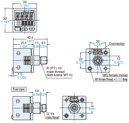
Dimensions
- Unit: mm in
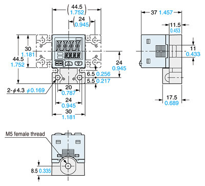
DP-10□(-P)
Sensor
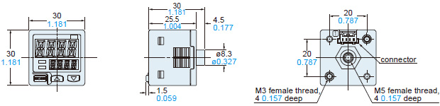
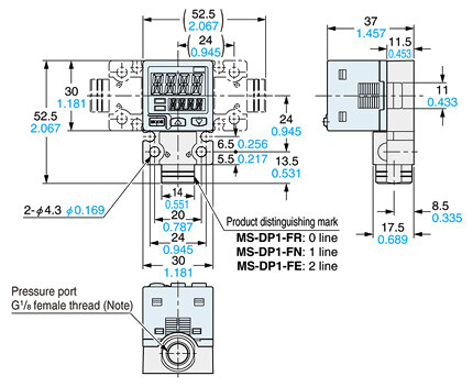
DP-10□-M(-P)
Sensor
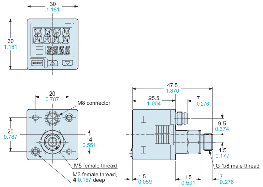
DP-11□-E-P-J
Sensor
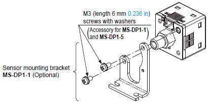
MS-DP1-1
Sensor mounting bracket (Optional)
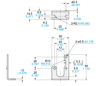
Material:Cold rolled carbon steel (SPCC)(Trivalent uni-chrome plated)Two M3 (length 6 mm0.236 in) screws with washers are attached
Assembly dimensions
Mounting drawing with DP-10□(-P)
MS-DP1-5
Sensor mounting bracket (Optional)
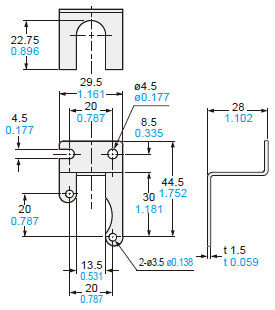
Material:Stainless steel (SUS304)Two M3 (length 6 mm0.236 in) screws with washers are attached
Assembly dimensions
Mounting drawing with DP-10□-M(-P)
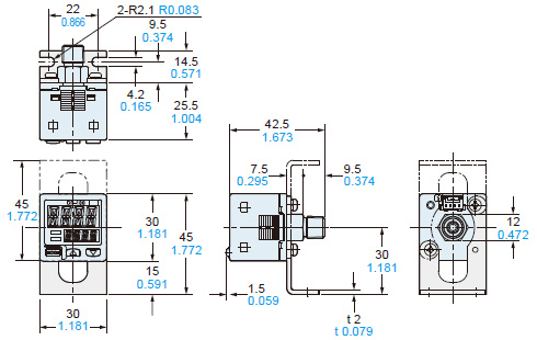
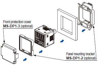
MS-DP1-2
MS-DP1-3
Panel mounting bracket (Optional),
Front protection cover (Optional)
Assembly dimensions
Mounting drawing with DP-10□(-P)
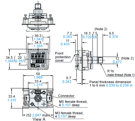
Material:Polyacetal (Panel mounting bracket)Polycarbonate (Front protection cover)Notes:1) DP-10□-E-P has a G1/8 male thread. DP-10□-N(-P) has a NPT1/8 male thread.2) In case of DP-10□-E-P, the dimension 7.5 become to be 10, the dimension 9.5 become to be 7 and the dimension 12 become to be 14.
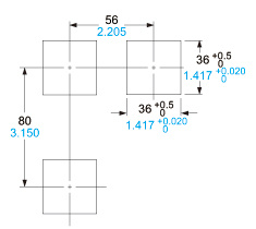
Panel cut-out dimensions
When 1 unit is installed
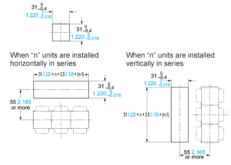
Note:The panel thickness should be 1 to 6 mm0.039 to 0.236 in.
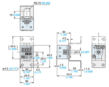
MS-DP1-4
Panel mounting bracket (Optional)
Assembly dimensions
Mounting drawing with DP-10□(-P)

Material:Nylon 6 (Panel mounting bracket body)Stainless steel (SUS304) (Panel mounting bracket)Cold rolled carbon steel (SPCC) (Trivalent uni-chrome plated) (Spacer)Notes:1) DP-10□-E-P has a G1/8 male thread. DP-10□-N(-P) has a NPT1/8 male thread.2) The panel tickness should be 1 to 32 mm0.039 to 1.260 in.
Panel cut-out dimensions
Note:The panel thickness should be 1 to 3.2 mm0.039 to 0.126 in.
MS-DP1-7
Conversion bushing (Optional)
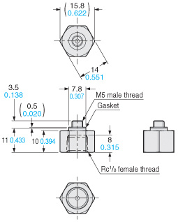
Material: Brass (Nickel plated)Weight: 10g approx.
MS-DP1-FM
Flat attachment (Optional)
Assembly dimensions
Mounting drawing with DP-10□-M(-P)
Material:Polybutylene terephthalate (PBT) (Glass fiber reinforced) (Enclosure)Stainless steel (SUS303) (Pressure port)Hydrogenated Nitrile Butadiene Rubber (H-NBR) (O-ring)Weight: 15g approx.(flat attachment only)Two M3 (length 8mm0.315 in) screws, two M4 (length 20mm0.787 inscrews are attached.
MS-DP1-FR
MS-DP1-FN
MS-DP1-FE
Flat attachment (Optional)
Assembly dimensions
Mounting drawing with DP-10□-M(-P)
Note:MS-DP1-FR has a Rc1/8 female thread.MS-DP1-FN has a NPT1/8 female thread.Material:Polybutylene terephthalate (PBT) (Glass fiber reinforced) (Enclosure)Stainless steel (SUS303) (Pressure port)Hydrogenated Nitrile Butadiene Rubber (H-NBR) (O-ring)Weight: 25g approx. (flat attachment only)Two M3 (length 8mm0.315 in screws, two M4 (length 20mm0.787 in screws are attached.
CN-14A-C□
CN-14A-R-C□
Connector attached cable (Optical, CN-14A-C2 is attached to the sensor)
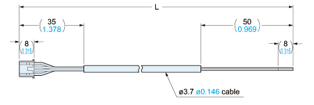
・Length L
| Model No. | Cable length L (mm in) |
|---|---|
| CN-14A(-R)-C1 | 1,000 39.370 |
| CN-14A(-R)-C2 | 2,000 78.740 |
| CN-14A(-R)-C3 | 3,000 118.110 |
| CN-14A(-R)-C5 | 5,000 196.850 |
------------------------------ Tab8 showing ------------------------------
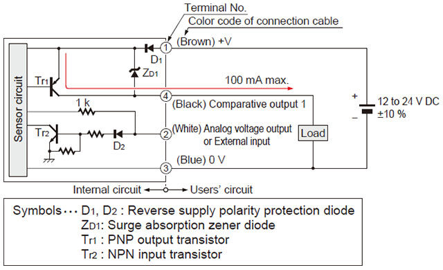
I/O Circuit and Wiring diagrams
DP-10□ NPN output type
I/O circuit diagrams
Standard type
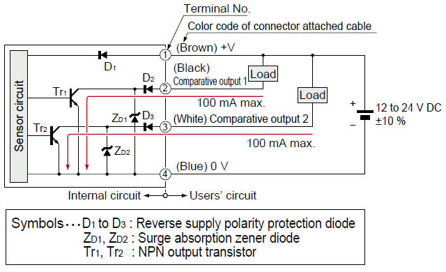
Multi-function type
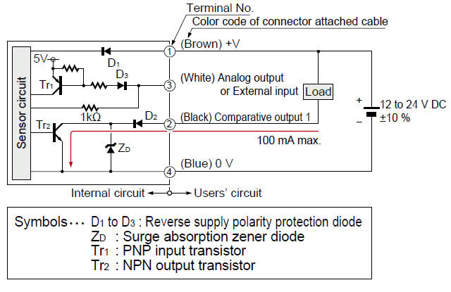
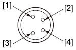
Terminal arrangement diagram
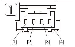
| Terminal | Designation |
|---|---|
| [1] | +V |
| [2] | Comparative output 1 |
| [3] | Standard type: Comparative output 2 Multi-function type: Analog output or External input |
| [4] | 0V |
DP-10□-P PNP output type
I/O circuit diagrams
Standard type

Multi-function type
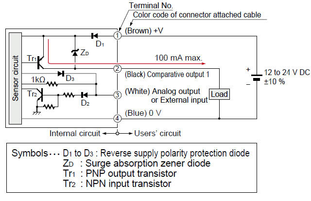
Terminal arrangement diagram
| Terminal | Designation |
|---|---|
| [1] | +V |
| [2] | Comparative output 1 |
| [3] | Standard type: Comparative output 2 Multi-function type: Analog output or External input |
| [4] | 0V |
DP-11□-E-P-J PNP output type
I/O circuit diagrams
Standard type
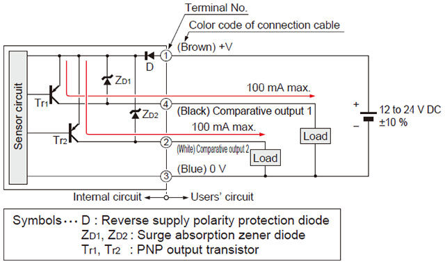
Multi-function type
Terminal arrangement diagram
| Terminal | Designation |
|---|---|
| [1] | +V |
| [2] | Standard type: Comparative output 2 Multi-function type: Analog output or External input |
| [3] | 0V |
| [4] | Comparative output 1 |
------------------------------ Tab9 showing ------------------------------
Part description
Wiring
- Make sure that the power supply is off while wiring.
- Verify that the supply voltage variation is within the rating.。
- If power is supplied from a commercial switching regulator, ensure that the frame ground (F.G.) terminal of the power supply is connected to an actual ground.
- In case noise generating equipment (switching regulator, inverter motor, etc.) is used in the vicinity of this sensor, connect the frame ground (F.G.) terminal of the equipment to an actual ground.
- Do not run the wires together with high-voltage lines or power lines or put them in the same raceway. This can cause malfunction due to induction.
- Incorrect wiring will cause problems with operation.
Connection
- Do not apply stress directly to the connection cable leader or to the connector.
Conditions in use for CE and UKCA conformity
- The DP-100 series is a CE and UKCA conformity product complying with EMC Directive. The harmonized standard with regard to immunity that applies to this product is EN 61000-6-2 and the following condition must be met to conform to that standard.
[Condition]
・The line to connect with this sensor should be less than 30 m 98.425 ft.
Mounting
- MS-DP1-1 / MS-DP1-5 sensor mounting brackets are available separately, and it should be used for mounting. When tightening the sensor to the sensor mounting bracket, use a tightening torque of 0.5 N·m or less.
- The MS-DP1-2 panel mounting bracket (optional) and the MS-DP1-3 front protection cover (optional) are also available.
- The MS-DP1-4 panel mounting bracket is available when switching from the DP2 / DP3 series.
- An conversion bushing is available for when using the DP-10□-M(-P) short pressure port type. It can be used to switch between this model and the DP2 / DP3 series. When connecting to the pressure port, use a tightening torque of 1.0 N・m or less.
(1) Decide the direction of this product to mount with the sensor.
- The MS-DP1-F□ flat attachment is available for when using the DP-10□-M short pressure port type. If using the MS-DP1-F□ flat attachment (optional), install by following the procedures given below.
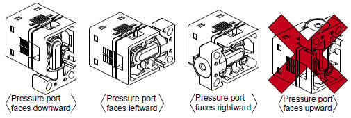
Note: It is not possible to mount this product such that the pressure port faces upward.
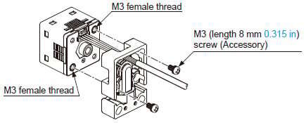
(2) Mount this product with the M3 female threads of the sensor by using the attached M3 (length 8 mm 0.315 in) screws. The tightening torque should be 0.5 N・m or less.
(3) Mount this product with the mounting surface by using the attached M4 (length 20 mm 0.787 in) screws. The tightening torque should be 1.2 N・m or less.
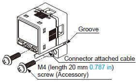
Note: Take care that if the cable with connector is sticking out of the side groove of this product when mounting, the cable may disconnected.
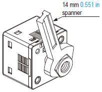
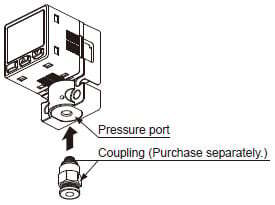
Piping
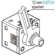
- If connecting a commercially-available coupling to the pressure port, attach a 12 mm 0.472 in spanner (14 mm 0.551 in spanner for DP-100-E type) to the hexagonal section of the pressure port to secure it, and tighten at a torque of 9.8 N・m or less. If it is tightened using excessive torque, it may damage the coupling or the pressure port. In addition, wrap sealing tape around the coupling when connecting it to prevent leaks.
- If connecting a commercially-available joint to the pressure port of the DP-10□-M(-P), hold the main unit in your hand to steady it, and tighten to a torque of 1.0 N・m or less. If it is tightened to an excessive torque, the joint or the main unit may become damaged.
- If connecting a commercially-available joint to the pressure port of the MS-DP1-7, tighten to a torque of 9.8 N・m or less.
- The tightening torque should be 1 N・m or less when connecting a coupling to the pressure port of MS-DP1-FM.
- When connecting the coupling to the pressure port of MS-DP1-FR/FE/FN, hold the pressure port with a 14 mm 0.551 in spanner and make sure that the tightening torque is 9.8 N・m or less.
In addition, in order to prevent any leakage, wind a sealing tape on the coupling when connecting.
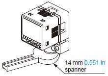
Note: Do not tighten the pressure port by holding the product with the spanner. It may cause the product breakage.
Flat attachment
- Make sure to mount MS-DP1-F□ with the sensor properly. If it is not mounted properly, air leakage may occur.
- Take care that the excessive mounting and dismounting of this product may cause deterioration of the O-ring.
- If you touch the O-ring of MS-DP1-F□, or any scratch or dust, etc. is attached to it, air leakage may occur and the sensing performance may deteriorate. Take sufficient care when using and storing MS-DP1-F□.
Others
- This product has been developed / produced for industrial use only.
- Use within the rated pressure range.
- Do not apply pressure exceeding the pressure withstandability value. The diaphragm will get damaged and correct operation shall not be maintained.
- Do not use during the initial transient time (0.5 sec. approx.) after the power supply is switched on.
- This product is suitable for indoor use only.
- The specification may not be satisfied in a strong magnetic field.
- Avoid dust, dirt, and steam.
- Take care that the sensor does not come in direct contact with water, oil, grease, or organic solvents, such as, thinner, etc.
- Do not insert wires, etc., into the pressure port.
The diaphragm will get damaged and correct operation shall not be maintained. - Do not operate the keys with pointed or sharp objects.
RUN mode
- This is the normal operating mode.
| Setting item | Description |
|---|---|
| Threshold value setting | The threshold values for ON / OFF operation can be changed directly by pressing the increment key (UP) and the decrement key (DOWN). |
| Zero-adjustment function | This forces the pressure value display to be reset to zero when the pressure port is open on the atmospheric pressure side. |
| Key lock function | Stops key operations from being accepted. |
| Peak hold / bottom hold function | Displays the peak value and bottom value for fluctuating pressure. The peak value appears in the main display, and the bottom value appears in the sub display. |
MENU SETTING mode
- If the mode selection key is pressed and held for 2 seconds in RUN mode, the mode will switch to MENU SETTING mode.
- If the mode selection key is pressed while a setting is being made, the mode will switch to RUN mode. In this case, the settings that have been changed will be entered.
| Setting item | Description |
|---|---|
| Comparative output 1 output mode setting | Sets the output mode for comparative output 1. |
| Comparative output 2 output mode setting (standard type only) | Sets the output mode for comparative output 2. |
| Analog output / external input switching (multi-function type only) | Allows switching between analog voltage output / analog current output, and auto-reference input / remote zero-adjust-ment input. |
| NO / NC switching | Sets normally open (NO) or normally closed (NC). |
| Response time setting | Sets the response time. The response time can be selected from 2.5 ms, 5 ms, 10 ms, 25 ms, 50 ms, 100 ms, 250 ms, 500 ms, 1,000 ms and 5,000 ms. |
| Display color switching for main display | Allows the color for the main display to be changed. The colors can be set to ‘red / green’ or ‘green / red' to correspond to ON / OFF output, or it can be fixed at ‘red’ or ‘green’ all the time. |
| Unit switching | Pressure unit can be changed. |
PRO mode
- If the mode selection key is pressed and held for 5 seconds in RUN mode, the mode will switch to PRO mode.
- If the mode selection key is pressed while a setting is being made, the mode will switch to RUN mode. In this case, the settings that have been changed will be entered.
| Setting item | Description |
|---|---|
| Sub display switching | Changes the information in the sub display during RUN mode operation to the desired alphanumeric display. |
| Display refresh rate switching | Changes the display refresh rate for the pressure value displayed in the main display. |
| Hysteresis fix value switching | Sets the hysteresis for EASY mode and window comparator mode. (8 steps) |
| Linked display color switching (standard type only) | Allows the display color for the main display to be switched in line with the output operation for comparative output 1 or comparative output 2. |
| ECO mode setting | Allows power consumption to be reduced by dimming the display or turning it off. |
| Setting check code | Allows the setting details to be checked via codes. |
| Setting copy mode | Allows the setting details for the master sensor to be copied to slave sensors. |
| Reset setting | Resets the settings to the factory settings. |
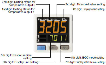
Table of codes
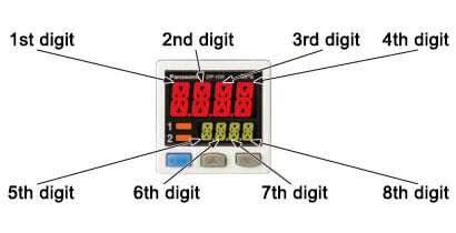
| Code | 1st digit | 2nd digit | 3rd digit | 4th digit | ||||
|---|---|---|---|---|---|---|---|---|
| Standard type | Multi-function type | Standard type only | ||||||
| Comparative output 1 output mode | NO/NC switching | Comparative output 2 output mode | NO/NC switching | Analog voltage output / External input | Threshold value display | Display color for main display | Display color linking | |
| 0 | EASY | NO | OFF | OFF | Analog voltage output | P-1, Lo-1 | Red when ON | Comparative output 1 |
| 1 | NC | EASY | NO | Auto reference | Hi-1 | Comparative output 2 | ||
| 2 | Hysteresis | NO | NC | Remote zero-adjustment | P-2, Lo-2 | Green when ON | Comparative output 1 | |
| 3 | NC | Hysteresis | NO | Analog current output | Hi-2 | Comparative output 2 | ||
| 4 | Window comparator | NO | NC | - | ADJ. | Always red | Comparative output 1 | |
| 5 | NC | Window comparator | NO | - | - | Comparative output 2 | ||
| 6 | - | - | NC | - | - | Always green | Comparative output 1 | |
| 7 | - | - | - | - | - | - | Comparative output 2 | |
| コード | 5th digit | 6th digit | 7th digit | 8th digit |
|---|---|---|---|---|
| Response time | Unit switching | Display refresh rate | ECO mode | |
| 0 | 2.5ms | MPa | 250ms | OFF |
| 1 | 5ms | kPa | 500ms | STD |
| 2 | 10ms | kgf/cm2 | 1,000ms | FULL |
| 3 | 25ms | bar | - | - |
| 4 | 50ms | psi | - | - |
| 5 | 100ms | mmHg | - | - |
| 6 | 250ms | inchHg | - | - |
| 7 | 500ms | - | - | - |
| 8 | 1,000ms | - | - | - |
| 9 | 5,000ms | - | - | - |