Discontinued Products
Dimensions
- Unit: mm in
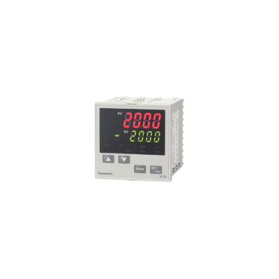
KT9 Series
General tolerance :
±1.0
±0.39
Panel cutout
Note) The communications terminal is the screw terminal on the back of the unit.
Shunt Resistor
AKT4810
Shunt resistor
Terminal Cover
AKT8801 (for KT8)
AKT9801 (for KT9)
* 2pcs of terminal cover of AKT8801 can be used as an AKT9801 cover.
Current Transformer (CT)
CT1
Current transformer (CT) (for 5, 10, and 20A)
CT2
Current transformer (CT) (for 50 A)
Note:Current transformer CT1 or CT2 is included (only with KT7 and KT4H)
when heater burnout alarm function is added.
Wiring/ Connection
External Connection Diagram
POWER SUPPLY : Power supply
OUT1 : Control output 1 (heat output)
OUT2 : Control output 2 (cooling output)
RELAY : Relay contact output
V/A : DC voltage output/direct current output
A1 : Alarm 1 output
A2 : Alarm 2 output
HB : Heater cutoff alarm output
SV2 : Second main setup
CT : CT input
TC : Thermocouple
RTD : Resistance temperature detection
DC : Direct current or DC voltage
RS-485 : Serial communications
*That main setting No. 2 will not be possible on the KT8 and KT9 when the communications functions is added.
Communication Function Connection Diagram (PLC Connection Diagram)
Cautions For Use
1.Notice on site selection
This instrument is intended to be used in the following environment (IEC61010-1) Overvoltage category II,
Pollution degree 2 Mount the controller in a place with:
- 1.A minimum of dust, and an absence of corrosive gases
- 2.No flammable, explosive gases
- 3.Few mechanical vibrations or shocks
- 4. No exposure to direct sunlight, an ambient temperature of 0 to 50°C (32 to 122 ℉) that does not change rapidly
- 5.An ambient non-condensing humidity of 35 to 85%RH
- 6.No large capacity electromagnetic switches or cables through which large current is flowing
- 7.No water, oil or chemicals or where the vapors of these substances can come into direct contact with the controller
2.Notice on wiring
- 1.The terminal block of KT4, 8 and 9 series are designed to be wired from the left side.
The lead wire must be inserted from the left side of the terminal, and fastened by the terminal screw.
Use a solderless terminal with insulation sleeve that fits to the M3 screw.
- 2.Terminal fastening torque is approximately 0.6N·m to 1.0N·m (KT4, 8 and 9).
For KT7 series by M2.6 screw is less than 0.5N·m and by M2.0 screw 0.25N·m respectively. - 3.Use a thermocouple and compensating lead wire according to the input specification of the controller.
- 4.Use a 3-wire system of RTD according to the input specification of the controller.
- 5.This controller has no built-in power switch, circuit breaker or fuse. Therefore, it is necessary to install them in the circuit near the external controller.
(Recommended fuse: Time-lag fuse, rated voltage 250V AC, rated current 2A) - 6.In the case of 24V AC/DC power supply, do not confuse the polarity when it is DC.
- 7.With the relay contact output type, use an auxiliary electromagnetic switch externally according to the capacity of the load to protect the built-in relay contact.
- 8.When wiring, keep input wire (thermocouple, RTD, etc.) away from AC source and load wire to avoid external interference.
- 9.Turn the power supply to the instrument off before wiring or checking. Working or touching the terminal with the power switched on may result in Electric Shock which could cause severe injury or death.
- 10.Do not drop wire chips into the holes of vent when wiring, because they could cause fire, malfunction or trouble with the device.
- 11.To prevent the unit from harmful effects of unexpected high level noise, it is recommended that a surge absorber be installed between the electromagnetic switch coils.
3.Notice on the mounting
- 1.Do not use excessive force while screwing in the mounting bracket of KT4, 8 and 9 series. Recommended torque is approximately 0.12N·m.
- 2.When mounting the KT7 series to the DIN rail, mount it in a lateral direction. Make sure a click is audible when fixed into place.
4.Optional heater burn-out alarm output
- 1.This alarm is not available for detecting current under phase control.
- 2.Use the current transformer (CT) provided, and pass one lead wire of the heater circuit into the hole of CT.
- 3.When wiring, keep CT wire away from AC source and load wire to avoid external interference.