HL (AZH) Micro Limit Switch (Discontinued Products)
Download
-
Discontinued Products
-
Rating/ Performance
-
Dimensions
-
Cautions For Use
Ⅾiscontinued
Last time buy (JST)
September 30, 2018
Discontinued Products

Ratings
| Load | Standard type | Bifurcated type | ||||
|---|---|---|---|---|---|---|
| Resistive | Lamp | Inductive | Motor | Resistive | ||
| N.C. | N.O. | |||||
| 125 V AC | 5A | 1.5A | 3A | 2A | 1A | 0.1A |
| 250 V AC | 5A | 1.5A | 3A | 1A | 0.5A | - |
| 8 V DC | 5A | - | 1.5A | - | - | 0.1A |
| 14 V DC | 5A | - | 1.5A | - | - | 0.1A |
| 24 V DC | - | - | - | - | - | - |
| 30 V DC | 5A | - | 1.5A | - | - | 0.1A |
| 125 V DC | 0.5A | - | 0.05A | - | - | - |
| 250 V DC | 0.25A | - | 0.03A | - | - | - |
Notes)
1. The values above indicate steady-state current.
2. Parameter of inductive load: AC power factor: Min. 0.4; DC time constant: Max. 7 ms.
3. Lamp load generates 10 times of inrush current.
4. Motor load generates 6 times of inrush current.
| 1. | The values above indicate steady-state current. |
|---|---|
| 2. | Parameter of inductive load: AC power factor: Min. 0.4; DC time constant: Max. 7 ms. |
| 3. | Lamp load generates 10 times of inrush current. |
| 4. | Motor load generates 6 times of inrush current. |
Characteristics
| タイプ | Standard type | Bifurcated type | ||
|---|---|---|---|---|
| Screw terminal type | Connector type | |||
| Contact arrangement | 1 Form C | 1 Form C (Bifurcated contact) | ||
| Contact resistance | Initial: Max. 15 mΩ | Initial: Max. 100 mΩ | Initial: Max. 150 mΩ | |
| Contact material | AgCdO | Au clad Ag alloy (Cadmium free) | ||
| Insulation resistance | Initial: Min. 100MΩ (at 500 V DC) | |||
| Initial breakdown voltage | 1,000 Vrms for 1 min. between non-consecutive terminals 1,500 Vrms for 1 min. between dead metal parts and terminals 1,500 Vrms for 1 min. between ground and terminals | |||
| Shock resistance | Free position | Max. 98 m/s2 {10 G} | ||
| Full operating position | Max. 294 m/s2 {30 G} | |||
| Vibration resistance | 10 to 55 Hz (Double amplitude for max. 1.5 mm) | |||
| Mechanical life | 107 (at 120 cpm) | |||
| Electrical life | 5×10⁵ (at 20 cpm, 5 A 250 V AC resistive load) | 5×10⁵ (at 20 cpm, 0.1 A 125 V AC resistive load) | ||
| Ambient temperature | -10 to +80 ℃ +14 to +176 ℉ | |||
| Ambient humidity | Max. 95% R.H. | |||
| Max. switching frequency | Max. 120 cpm | |||
Protective characteristics
| Protective construction | Die cast case | Plastic case |
|---|---|---|
| IEC | ||
| IP64 | ○ | ○ |
| IP67 | ○ | - |
Operating characteristics
Die casting case
| Characteristics | Operating force, max. N (gf) | Release force, min. N (gf) | Pretravel, max. mm (inch) | Movement differential, max. mm (inch) | Overtravel, min. mm (inch) | Operating position, max. mm (inch) |
|---|---|---|---|---|---|---|
| Panel mount push plunger | 11.8 (1200) | 4.90 (500) | 1.5 (0.059) | 0.1 (0.004) | 3.0 (0.118) | 17.4±0.8 (0.685±0.031) |
| Panel mount roller plunger | 11.8 (1200) | 4.90 (500) | 1.5 (0.059) | 0.1 (0.004) | 3.0 (0.118) | 23.4±0.8 (0.921±0.031) |
| Panel mount cross roller plunger | 11.8 (1200) | 4.90 (500) | 1.5 (0.059) | 0.1 (0.004) | 3.0 (0.118) | 23.4±0.8 (0.921±0.031) |
| Sealed push plunger | 11.8 (1200) | 4.90 (500) | 1.5 (0.059) | 0.1 (0.004) | 3.0 (0.118) | 30.0±0.8 (1.181±0.031) |
| Sealed roller plunger | 11.8 (1200) | 4.90 (500) | 1.5 (0.059) | 0.1 (0.004) | 3.0 (0.118) | 41.3±0.8 (1.626±0.031) |
| Sealed cross roller plunger | 11.8 (1200) | 4.90 (500) | 1.5 (0.059) | 0.1 (0.004) | 3.0 (0.118) | 41.3±0.8 (1.626±0.031) |
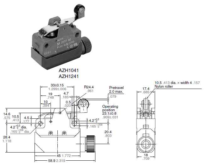
| Short roller lever | 3.92 (400) | 0.78 (80) | 2.0 (0.079) | 0.3 (0.012) | 4.0 (0.157) | 23.1±0.8 (0.909±0.031) |
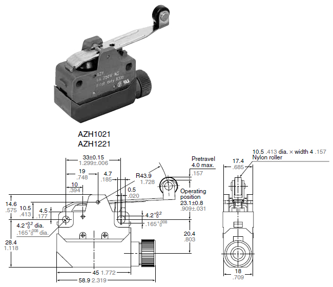
| Roller lever | 2.45 (250) | 0.39 (40) | 4.0 (0.157) | 0.6 (0.024) | 7.0 (0.276) | 23.1±0.8 (0.909±0.031) |
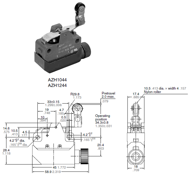
| One-way short roller lever | 3.92 (400) | 0.78 (80) | 2.0 (0.079) | 0.3 (0.012) | 4.0 (0.157) | 34.3±0.8 (1.350±0.031) |
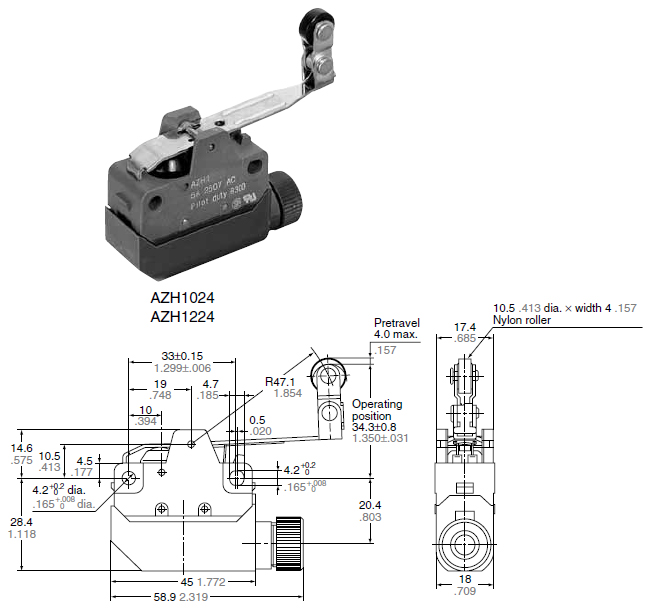
| One-way short lever | 2.45 (250) | 0.39 (40) | 4.0 (0.157) | 0.6 (0.024) | 7.0 (0.276) | 34.3±0.8 (1.350±0.031) |
Plastic case
| Characteristics | Operating force, max. N (gf) | Release force, min. N (gf) | Pretravel, max. mm (inch) | Movement differential, max. mm (inch) | Overtravel, min. mm (inch) | Operating position, max. mm (inch) |
|---|---|---|---|---|---|---|
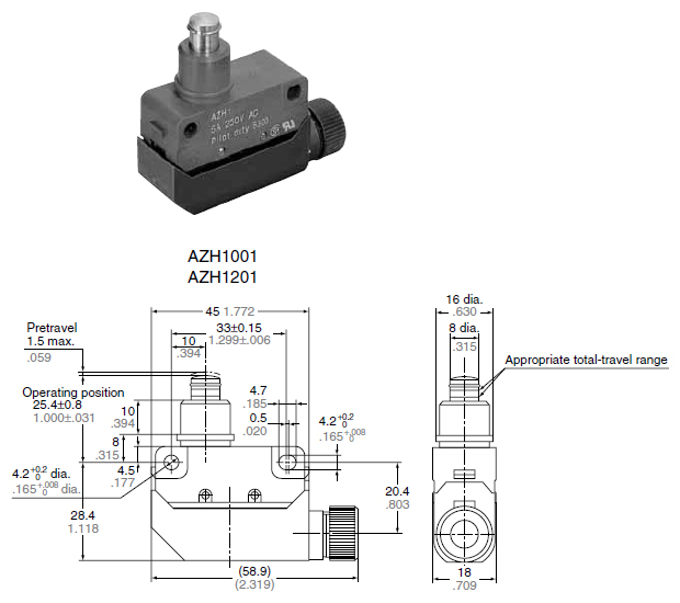
| Push plunger | 5.88 (600) | 0.98 (100) | 1.5 (0.059) | 0.1 (0.004) | 3.0 (0.118) | 25.4±0.8 (1.000±0.031) |
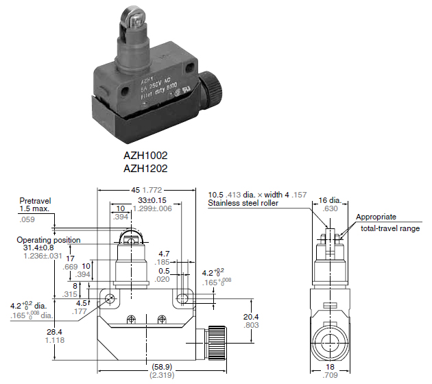
| Roller plunger | 5.88 (600) | 0.98 (100) | 1.5 (0.059) | 0.1 (0.004) | 3.0 (0.118) | 31.4±0.8 (1.236±0.031) |
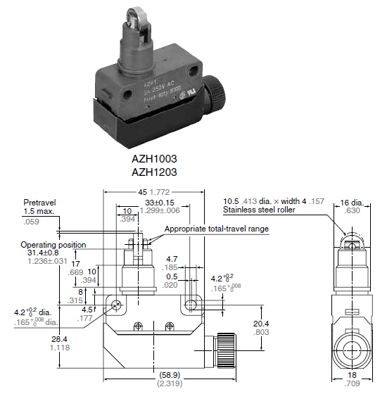
| Roller plunger | 5.88 (600) | 0.98 (100) | 1.5 (0.059) | 0.1 (0.004) | 3.0 (0.118) | 31.4±0.8 (1.236±0.031) |
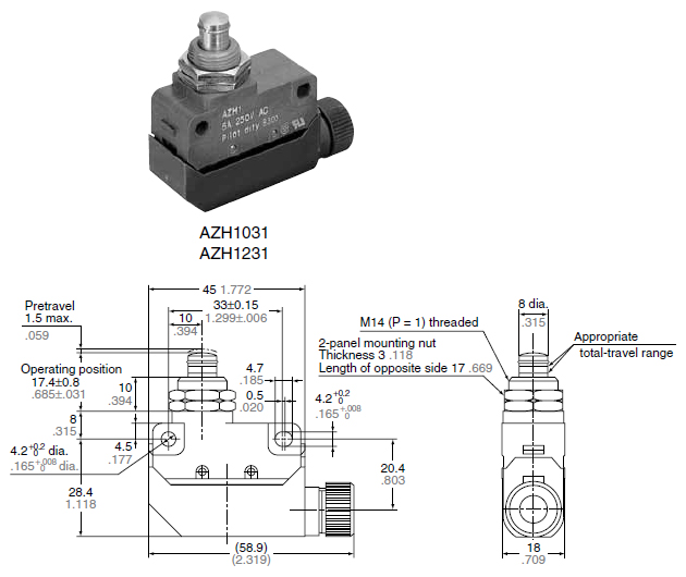
| Panel mount push plunger | 5.88 (600) | 0.98 (100) | 1.5 (0.059) | 0.1 (0.004) | 3.0 (0.118) | 17.4±0.8 (0.685±0.031) |
| Panel mount roller plunger | 5.88 (600) | 0.98 (100) | 1.5 (0.059) | 0.1 (0.004) | 3.0 (0.118) | 23.4±0.8 (0.921±0.031) |
| Panel mount cross roller plunger | 5.88 (600) | 0.98 (100) | 1.5 (0.059) | 0.1 (0.004) | 3.0 (0.118) | 23.4±0.8 (0.921±0.031) |
| Sealed push plunger | 5.88 (600) | 0.98 (100) | 1.5 (0.059) | 0.1 (0.004) | 3.0 (0.118) | 30.0±0.8 (1.181±0.031) |
| Sealed push plunger | 5.88 (600) | 0.98 (100) | 1.5 (0.059) | 0.1 (0.004) | 3.0 (0.118) | 41.3±0.8 (1.626±0.031) |
| Sealed cross roller plunger | 5.88 (600) | 0.98 (100) | 1.5 (0.059) | 0.1 (0.004) | 3.0 (0.118) | 41.3±0.8 (1.626±0.031) |
| Short roller lever | 3.92 (400) | 0.78 (80) | 2.0 (0.079) | 0.3 (0.012) | 4.0 (0.157) | 23.1±0.8 (0.909±0.031) |
| Roller lever | 2.45 (250) | 0.39 (40) | 4.0 (0.157) | 0.6 (0.024) | 7.0 (0.276) | 23.1±0.8 (0.909±0.031) |
| One-way short roller lever | 3.92 (400) | 0.78 (80) | 2.0 (0.079) | 0.3 (0.012) | 4.0 (0.157) | 34.3±0.8 (1.350±0.031) |
| One-way short lever | 2.45 (250) | 0.39 (40) | 4.0 (0.157) | 0.6 (0.024) | 7.0 (0.276) | 34.3±0.8 (1.350±0.031) |
| Flexible | 0.88 (90) | - | 30.0 (1.181) | - | 20.0 (0.787) | - |
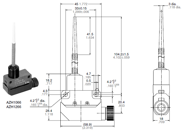
Dimensions
- Unit: mm in
General tolerance : ±0.4 ±0.016
Die cast case
Screw terminal type
Panel mount push plunger

Panel mount roller plunger

Panel mount cross roller plunger

Sealed push plunger

Sealed roller plunger

Sealed cross roller plunger

Short roller lever

Roller lever

One-way short roller lever

One-way roller lever

Connector type
Panel mount push plunger

Panel mount roller plunger

Panel mount cross roller plunger

Sealed push plunger

Sealed roller plunger

Sealed cross roller plunger

Short roller lever

Roller lever

One-way short roller lever

One-way roller lever

Plastic case
Push plunger
Roller plunger
Cross roller plunger
Panel mount push plunger
Panel mount roller plunger

Panel mount cross roller plunger
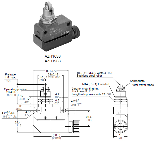
Sealed push plunger
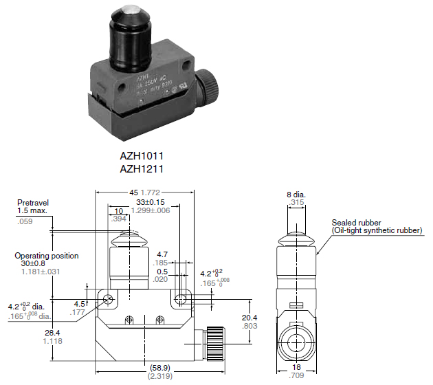
Sealed roller plunger
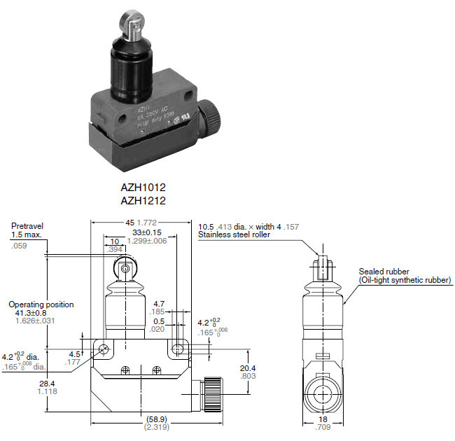
Sealed cross roller plunger
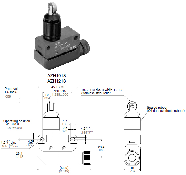
Short roller lever
Roller lever
One-way short roller lever
One-way roller lever
Flexible
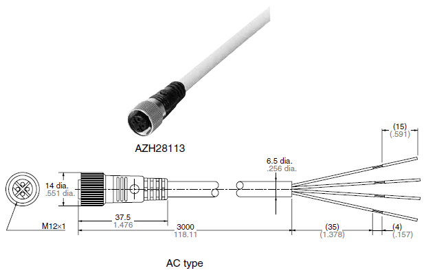
Cable connected cord
Straight type
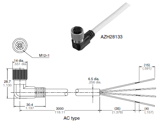
Angle type
Cautions For Use
Common for all types
- This limit switch is designed under the premise that it will be used in a standard industrial device. Accordingly, there are limits as to what can be tolerated if used outdoors or where water and oil, etc., may get on the device.
The following table indicates how much water and oil can be withstood (classification of protective structure).
| Plastic case (AZH1*) | Die casting case (AZH2*) | |
|---|---|---|
| Protective classification | IP64 | IP67 |
| Testing method | No harmful effect when sprayed with water for 10 minutes from all angles. | Water does not enter product after immersion in water 1 m 3.281 ft deep for 30 minutes. |
| Limits on use | Cannot be used outdoors or in a place where water and oil, etc., will continually contact the device. | Cannot be used outdoors where it can be rained on directly and cannot be used submersed in water or in oil, etc. |
Note:
Although, initially, the protective classification complies under the testing above, due consideration must be taken because great differences may result depending on factors such as duration of operation, installation method, and environment.
- The internal mechanism will break if the actuator is moved beyond its Total-travel (T.T.). Always use within the T.T.
Die casting case
- Do not expose HL limit switch to hot water (over 60℃ +140℉) and in a water vapor environment.
- Avoid the place where organic solvents, strong acid, strong alkali liquid and vapor may attach to the products directly. Prevent using the HL limit switch in place where inflammable or corrosive gas will be generated.
- Do not change the operating position by bending the actuator.
- Use within an ambient temperature of –10 to 80℃. +14 to +176℉ (However, do not allow it to freeze.)
- If O.T. is too big, the life of limit switch will be shortened by switching friction.
Use it with enough margin of O.T. 70 % of O.T. standard value will be good. - Attach the terminal cover securely to the body with the metal stop latch to the projection of the body.
- Confirmation test in the actual application is highly recommended.
- Do not use the switch in a silicon atmosphere. Care should be taken where organic silicon rubber, adhesive, seling material, oil, grease or lead wire generates silicon.
- This is designed to use inside. When used outdoors (in places where there is exposure to direct sunlight or rain such as in multistory car parks) or in environments where ozone is generated, the influence of these environments cause deterioration of the rubber material and damage for the products.
- Avoid use in excessively dusty environments where actuator operation would be hindered.
Plastic case
- Do not use in water or oil.
Do not place the switch where it is always exposed to water or dust splash. - Do not expose HL limit switch to hot water (over 60℃ +140℉) and in a water vapor environment.
- Avoid the place where organic solvents, strong acid, strong alkali liquid and vapor may attach to the products directly. Prevent using the HL limit switch is place where inflammable or corrosive gas will be generated.
- Do not change the operating position by bending the actuator.
- Use within an ambient temperature of –10 to 80℃. +14 to +176℉ (However, do not allow it to freeze.)
- If O.T. is too big, the life of limit switch will be shortened switching friction. Use it with enough margin of O.T. 70 % of O.T. standard value will be good for use.
- Attach the terminal cover securely to the body to the extent you can identify the clicking or locking sound.
- A confirmation test in the actual application is highly recommended.
- Do not use the switch in a silicon atmosphere. Case should be taken where organic silicon rubber, adhesive, sealing material, oil, grease or lead wire generates silicon.
- This is designed to use inside. When used outdoors (in places where there is exposure to direct sunlight or rain such as in multistory car parks) or in environments where ozone is generated, the influence of these environments cause deterioration of the rubber material and damage for the products.
- Avoid use in excessively dusty environments where actuator operation would be hindered.