Discontinued Products
Specifications
RATING
1.Standard speed
| Part number | Rated voltage (V) | Input power (W) max/AVE | Rated current (mA) max/AVE | Rotation speed (min-1) min/AVE | Max. air flow (m3/min) min/AVE | Max. static pressure (Pa) min/AVE | Noise (dB) max/AVE | Weight (g) |
|---|---|---|---|---|---|---|---|---|
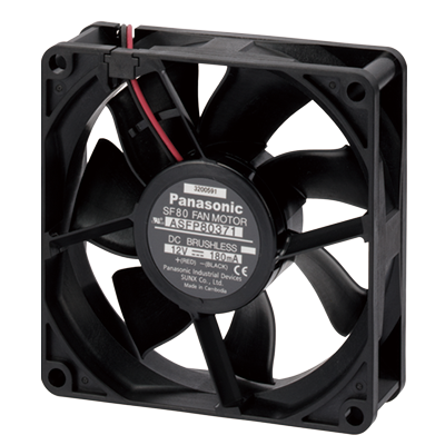
| ASFP80371 | 12 | 2.16/1.68 | 180/140 | 2,900/3,100 | 1.07/1.17 | 32.0/37.5 | 35.0/30.0 | 80 |
| ASFP80372 | 24 | 2.16/1.92 | 90/80 |
2.Middle speed
| Part number | Rated voltage (V) | Input power (W) max/AVE | Rated current (mA) max/AVE | Rotation speed (min-1) min/AVE | Max. air flow (m3/min) min/AVE | Max. static pressure (Pa) min/AVE | Noise (dB) max/AVE | Weight (g) |
|---|---|---|---|---|---|---|---|---|
| ASFP82371 | 12 | 0.96/0.72 | 80/60 | 2,100/2,300 | 0.76/0.86 | 17.0/21.5 | 27.0/22.0 | 80 |
| ASFP82372 | 24 | 1.20/0.96 | 50/40 |
3.Low speed
| Part number | Rated voltage (V) | Input power (W) max/AVE | Rated current (mA) max/AVE | Rotation speed (min-1) min/AVE | Max. air flow (m3/min) min/AVE | Max. static pressure (Pa) min/AVE | Noise (dB) max/AVE | Weight (g) |
|---|---|---|---|---|---|---|---|---|
| ASFP84371 | 12 | 0.72/0.60 | 60/50 | 1,800/2,000 | 0.65/0.74 | 12.5/16.5 | 24.0/19.0 | 80 |
| ASFP84372 | 24 | 0.96/0.72 | 40/30 |
Note: 1 Values above without designations are averages.
Note: 2 Noise levels are based on measurements taken at a distance of 1 m from the front of the fan.
SPECIFICATIONS
| Ambient temperature | -10℃ to +60℃ +14℉ to +140℉ | |
|---|---|---|
| Humidity resistance test condition | 85 ℃ 185 ℉, 95% RH, 240 hrs. | |
| Temperature rise | Coil surface: Max. 50℃ 122℉ (Nominal voltage, by resistive method) Exterior:Max. 20℃ 68℉ (Nominal voltage, by thermocouple method) | |
| Breakdown voltage | 500 V AC for 1 min. (between lead wire and external housing) | |
| Insulation resistance | Min. 10 MΩ (at 500 V DC) | |
| Vibration resistance | Frequency | 10 to 55Hz |
| Double amplitude width | 0.75mm | |
| Applied direction | X, Y and Z directions | |
| Applied time | 10 min. in each direction | |
| Lead wire tensile strength | 9.8 N, single wires did not break at 15 seconds | |
| Fan blockage | No coil burnout even after blockage of 72 hrs. at nominal voltage. | |
| Reverse polarity power connection | No damage even after reverse polarity connection for short time at nominal voltage. | |
| Expected life | 40,000 hours at 60 ℃ (Life time when continuously energized by applying the rated voltage Current value: + 15% or more Rotation speed: -15% or less) | |
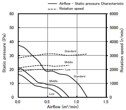
DATA (Airflow - Static pressure Characteristic Curve)
MATERIALS USED
| Frame | plastic |
|---|---|
| Propeller | plastic |
| Bearings | ball bearings |
| Lead wires | UL3385 and AWG26 |
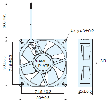
Dimensions
- Unit: mm in
ASFP8
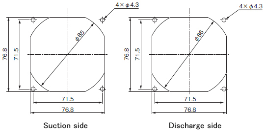
Mounting Hole Dimensions
Cautions For Use
DC fan motor
- Do not reverse-connect the power supply. Although nothing adverse will occur if the rated voltage is connected in reverse for a short time period, the fan will not operate.
DC fan motor and AC fan motor
- Since our fan motor employs precision ball bearings, due care should be taken not to apply any shock in handling.
- Due to the bearing mechanism, the noise level will increase in proportion to the length of time the fan is used.
Avoid use where the temperature is high or where there is a lot of dirt. - Do not allow substances such as oil and grease to get onto the plastic part of the fan body. Some oils and greases decompose and become altered at high temperatures. These can have an adverse effect if they contact the fan.
Therefore, be very careful when handling these substances. - Do not apply unnecessary force to the internal parts when handling the product. Also, do not use a fan that has been dropped.
- Installation
Install according to the diagrams below.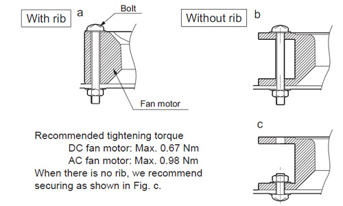
- Regarding the life of the fan, the ambient temperature is 60 ℃.
The life of the fan varies depending on the operating frequency, usage time, surrounding atmosphere, etc., so please check with the actual conditions.
- Transport and storage conditions
The allowable specifications for environments suitable for transportation and storage are given below.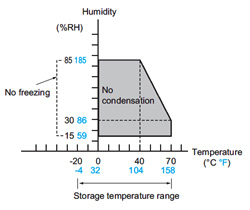
・No freezing between -20 ℃ to 0 ℃ -4 ℉ to +32 ℉
・No condensation in the range above between 0 ℃ to +70 ℃ +32 ℉ to +158 ℉ - Condensation
If the temperature is high and there is a lot of humidity, condensation will occur when the temperature suddenly changes.
This should be avoided because it can cause degradation of the fan insulation. - Freezing
At temperatures 0 ℃ +32 ℉ moisture such as that caused by condensation will freeze and lead to problems such as lockage of the moving parts and operation lags. Be careful to prevent this from happening. - Low-temperature, low-humidity environments
Do not leave the fan for a long period in an environment of low temperature and low humidity. Doing so may cause the plastic to become brittle. - When storing, avoid places of high temperature and high humidity or where corrosive gas is present.
- Do not store the fan any longer than six months.
FUNCTIONS OF DC FAN SENSOR
In case of the fan stops as a result of forced external restraint, a signal will be generated to indicate that there is a problem. This signal can be used to control an external warning circuit in order to help prevent the device from overheating. Although there are various detection methods for this sensor, we adopt the method that uses a logic circuit.
1. Lock sensor specifications
Output waveform
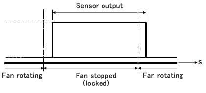
*Output may be high for approximately 0.5 seconds when power is turned on.*The continually high output waveform type when fan is stopped (locked) is standard. A output waveform type that corresponds to the rotation frequency during fan rotation is available by special order. Please inquire for details.
2. Sensor output circuit
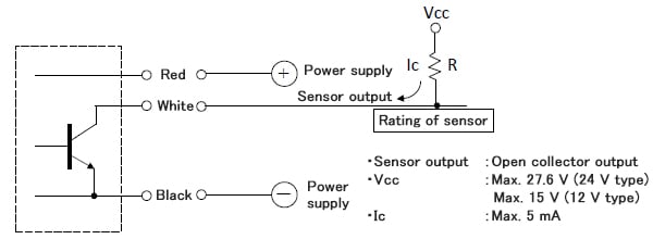
Note 1: Set the resistance value (R) so that the sensor circuit current (Ic) does not exceed 5 mA.* Exceeding the values above may lead to IC damage.