LC4H-S Electronic Counters (with pre-scale function) (Discontinued Products)
Download
-
Discontinued Products
-
Rating/ Performance
-
Dimensions
-
Wiring/ Connection
-
Cautions For Use
Ⅾiscontinued
Last time buy (JST)
December 28, 2022
We are sorry, the products have been discontinued. Please refer to the details of the discontinued products and the recommended substitutes list below.
Discontinued Products

Rating/ Performance
| Type | Ralay output type | Transistor output type | |||
|---|---|---|---|---|---|
| Item | AC type | DC/AC type | DC/AC type | ||
| Rating | Rated operating voltage | 100 to 240 V | 12 to 24 V DC/24 V AC | 12 to 24 V DC/24 V AC | |
| Rated frequency | 50/60 Hz common | ||||
| Rated power consumption | Max. 10 V A | Max. 3 W | |||
| Rated control capacity | 5 A 250 V AC (resistive load) | 100 mA, 30 V DC | |||
| Input mode | Addition (UP)/Subtraction (DOWN)/Direction (DIR)/Individuality (IND)/Phase (PHASE) 5 modes selectable by DIP switches | ||||
| Max. counting speed | 30 Hz, 5 kHz (selectable by DIP switches) | ||||
| Counting input (input 1, input 2) | 16.7 ms at 30 Hz/0.1 ms at 5 kHz ON time: OFF time = 1:1 | ||||
| Reset input | Min. input signal width: 1 ms, 20 ms (selected by DIP switches) | ||||
| Lock input | Min. input signal width: 20 ms | ||||
| Input signal | Contact, Open collector input/DC two-wire system sensor Input impedance: 1 kΩ or less, Input residual voltage: 2 V or less, Open impedance: 100 kΩ or less, Max. energized voltage: 40 V DC | ||||
| Output mode | HOLD-A, HOLD-B, HOLD-C, SHOT-A, SHOT-B, SHOT-C, SHOT-D, 7 modes selectable by DIP switches | ||||
| One shot output time | 1 s, 0.5s, 0.2s, 0.1s, 0.05, 0.01s | ||||
| Indication | 7-segment LCD, Counter value (backlight red LED), Setting value (backlight yellow LED) | ||||
| Digit | 4-digit display type --999 to 9999 (0 to 9999 for setting) 6-digit display type --99999 to 999999 (0 to 999999 for setting) | ||||
| Decimal point | Can be set to three digits | ||||
| Pre-scaling | 0.001 to 9.999 (4-digit type), 0.001 to 99.999 (6-digit type) | ||||
| Memory | EEP-ROM (Overwriting times: 105 ope. or more) | ||||
| Power for senser | 12 V DC (±10%) 100 mA Max. | - | |||
| Contact | Contact arrangement | 1 Form C | 1 Form A (Open collector) | ||
| Initial contact resistance | 100 mΩ (at 1 A 6 V DC) | - | |||
| Contact material | Ag alloy/Au flush | - | |||
| Life | Mechanical (contact) | 2×10⁷ ope. (Except for switch operation parts) | - | ||
| Electrical (contact) | 105 ope. (At rated control voltage) | 107 ope. (At rated control voltage) | |||
| Electrical | Operating voltage range | 85 to 264 V AC | 10.8 to 26.4 V DC, 20.4 to 26.4 V AC | ||
| Initial withstand voltage | Between live and dead metal parts: 2,000 Vrms for 1 min (pin type) Between input and output: 2,000 Vrms for 1 min | ||||
| Initial insulation resistance (At 500 V DC) | Between live and dead metal parts: Min. 100 MΩ (pin type) Between input and output: Min. 100 MΩ | ||||
| Temperature rise | Max. 65°C (under the flow of nominal operating current at nominal voltage) | ||||
| Mechanical | Vibration resistance | Functional | 10 to 55 Hz (1 cycle/min), single amplitude: 0.35 mm (10 min on 3 axes) | ||
| Destructive | 10 to 55 Hz (1 cycle/min), single amplitude: 0.75 mm (1 h on 3 axes) | ||||
| Shock resistance | Functional | Min. 98 m/s2 (4 times on 3 axes) | |||
| Destructive | Min. 294 m/s2 (5 times on 3 axes) | ||||
| Operating conditions | Ambient temperature | --10°C to 55°C/ +14°F to +131°F | |||
| Ambient humidity | Max. 85 % RH (non-condensing) | ||||
| Air pressure | 860 to 1,060 h Pa | ||||
| Connection | 11-pin/screw terminal | ||||
| Protective construction | IP66 (front panel with a rubber gasket) | ||||
Dimensions
- Unit: mm in
Dimensions for flush mounting (with adapter installed)
General tolerance : ±1.0 ±0.39

Dimensions for front panel installations

Installation panel cut-out dimensions
The standard panel cut-out dimensions are shown below.
Use the mounting frame (AT8-DA4) and rubber gasket (ATC18002).
For connected installations
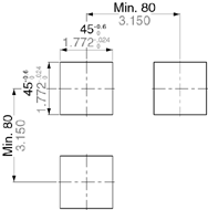
Note 2: For connected installations, the waterproofing ability between the unit and installation panel is lost.
Wiring/ Connection
Terminal Layouts and Wiring Diagrams
Pin type
Relay output type
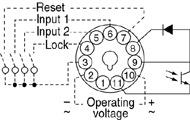
With power supply for sensor
Relay output type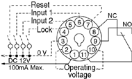

Screw terminal type
Relay output type
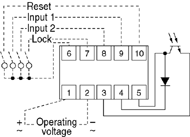
With power supply for sensor
Relay output type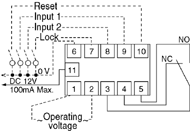

Cautions For Use
Protective circuit for timer contact
In the circuit that switches an inductive load, a contact failure may occur at a contact point due to surge or inrush current resulting from that switching. Therefore, it is recommended that the following protective circuit be used to protect the contact point.
| CR circuit (r: resistor c: capacitor) | |||
|---|---|---|---|
| Circuit |
|
| |
| Application | AC | * Note: | Available |
| DC | Available | Available | |
| Features/Others | If the load is a relay or solenoid, the release time lengthens. Effective when connected to both contacts if the power supply voltage is 24 or 48 V and the voltage across the load is 100 to 200 V. | ||
| If the load is a timer, leakage current flows through the CR circuit causing faulty operation. Note: If used with AC voltage, be sure the impedance of the load is sufficiently smaller than that of the CR circuit. | - | ||
| Device Selection | As a guide in selecting r and c, c: 0.5 to 1 µF per 1 A contact current r: 0.5 to 1 ohm per 1 V contact voltage Values vary depending on the properties of the load and variations in timer characteristics. Capacitor c acts to suppress the discharge the moment the contacts open. Resistor r acts to limit the current when the power is turned on the next time. Test to confirm. Use a capacitor with a breakdown voltage of 200 to 300 V. Use AC type capacitors (non-polarized) for AC circuits. | ||
| Diode circuit | Varistor circuit | ||
|---|---|---|---|
| Circuit |
|
| |
| Application | AC | Not Available | Available |
| DC | Available | Available | |
| Features/Others | The diode connected in parallel causes the energy stored in the coil to flow to the coil in the form of current and dissipates it as joule heat at the resistance component of the inductive load. This circuit further delays the release time compared to the CR circuit. (2 to 5 times the release time listed in the catalog) | Using the rated voltage characteristics of the varistor, this circuit prevents excessively high voltages from being applied across the contacts. This circuit also slightly delays the release time. Effective when connected to both contacts if the power supply voltage is 24 or 48 V and the voltage across the load is 100 to 200 V. | |
| Device Selection | Use a diode with a reverse breakdown voltage at least 10 times the circuit voltage and a forward current at least as large as the load current. In electronic circuits where the circuit voltages reverse breakdown voltage of about 2 to 3 times the power supply voltage. | - | |
Type of Load and Inrush Current
The type of load and its inrush current characteristics, together with the switching frequency are important factors which cause contact welding. Particularly for loads with inrush currents, measure the steady state current and inrush current and use a relay or magnet switch which provides an ample margin of safety. The table below shows the relationship between typical loads and their inrush currents.
| Type of load | Inrush current |
|---|---|
| Resistive load | Steady state current |
| Solenoid load | 10 to 20 times the steady state current |
| Motor load | 5 to 10 times the steady state current |
| Incandescent lamp load | 10 to 15 times the steady state current |
| Mercury lamp load | 1 to 3 times the steady state current |
| Sodium vapor lamp load | 1 to 3 times the steady state current |
| Capacitive load | 20 to 40 times the steady state current |
| Transformer load | 5 to 15 times the steady state current |
When you want large load and long life of the counter, do not control the load direct with a timer. When the timer is designed to use a relay or a magnet switch, you can acquire the longer life of the counter.
Connection of input (Except for LC4H-S/AC type)
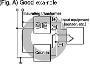
Since LC4H series counters use a transformerless power supply system, the input equipments must have the power supply transformer in which the secondary side is not grounded with the primary and secondary sides insulated, in order to prevent interference of the power supply circuit when connecting the external input circuit as Fig. A.
Be sure not to use an autotransformer. In case of secondary side grounded or using the autotransformer, this product may be destroyed due to short circuit electrically as Fig. B (1 and 2).
In case of F.G. terminal of equipments such a PLC grounded in secondary side of the transformer, inner circuits of this product and the input equipment may be destroyed due to short circuit electrically as Fig.B (3).
Therefore, use the isolated type counters or do not ground F.G. terminal of the products.


Long Continuous Current Flow
Avoid keeping the counter on for a long period of time (over one month). Otherwise heat is generated and accumulated inside the counter, which may deteriorate its electronic parts. If the counter must be kept on for a long period of time, a relay is added. See the circuit diagram below.

Leakage current
- 1.For connecting and disconnecting operating voltage to the counter, a circuit should be used, which will prevent the flow of leakage current. For example, a circuit for contact protection as shown in Fig A. will permit leakage current flow through R and C, causing erroneous operation of the counter. Instead, the circuit shown in Fig. B should be used.

- 2.If the counter is directly switched with a non-contact element, leak current may flow into the counter and cause it to malfunction.
Pin connections
Correctly connect the pins while seeing the pin layout/connection diagram. In particular, the DC type, which has polarities, does not operate with the polarities connected reverse. Any incorrect connection can cause abnormal heating or ignition.
Connection to operation power supply
- 1.Apply the entire supply voltage through a switch, relay or other contact.
- 2.The operation voltage for the DC type must be at the specified ripple percentage or less. The average voltage must fall within the allowable operation voltage range.
| Rectification type | Ripple percentage |
|---|---|
| Single-phase, full-wave | Approx. 48% |
| Three-phase, full-wave | Approx. 4% |
| Three-phase, half-wave | Approx. 17% |
- 3.Make sure that no induced voltage and residual voltage are applied between the power pins on the timer after the power switch is turned OFF.
(If the power line is wired in parallel with the high-voltage and motor lines, induced voltage may be produced between the power pins.)
Control output
- 1.Keep the load capacity below the counter's rated control capacity. If used above the rating, the counter's service life may shorten. With the transistor output type counters, transistors may be damaged.
Installing the counter
- 1.To install the counter, use the dedicated pin bracket or socket (cap). Avoid connecting the pins on the counter by directly soldering them.
- 2.In order to maintain the characteristics, do not remove the counter cover (case).
Superimposed surge of power supply
For the superimposed surge of power supply, the standard waveform (±1.2×50μs or ±1×40μs) is taken as the standard value for surge-proof voltage.
(The positive and negative voltages are applied each three or five times between the power pins.) For the standard values for the LC4H type counters, see the respective items in "Caution on usage."

If external surge occurs exceeding the specified value, the internal circuit may break down. In this case, use a surge absorption element. The typical surge absorption elements include a varistor, a capacitor, and a diode. If a surge absorption element is used, use an oscilloscope to see whether or not the foreign surge exceeding the specified value appears.
Signal input
The counter's signal input comes in two ways. One is by opening and closing the input terminal. The other is by applying a specified H-level or L-level voltage to the input terminal.
For an input sensor's residual voltage, input impedance, input voltage level and other signal input conditions, see the ratings for each type of product.
Operating environment
- 1.For the ambient operating temperature and humidity, see the ratings for each type of product.
- 2.Avoid using the counter in a location where (a) inflammable or corrosive gas is generated, (b) the counter is exposed to much dust and other foreign matter; (c) water or oil is splashed on the counter; or (d) vibrations or shocks are given to the counter.
- 3.The counter cover (case), the knobs, and the dials are made of polycarbonated resin. Therefore, prevent the counter from being exposed to organic solvents such as methyl alcohol, benzine, and thinner, strong acid substances such as caustic soda, and ammonia and avoid using the counter in atmosphere containing any of those substances.
- 4.If the counter is used where noises are emitted frequently, separate the input signal elements (such as a sensor), the wiring for the input signal line, and the counter as far as possible from the noise source and the high power line containing noises.

Checking the actual load
In order to increase the reliability in the actual use, check the quality of the counter in the actual usage.
Others
- 1. If the counter is used exceeding the ratings (operation voltage and control capacity), the contact life, or any other specified limit, abnormal heat, smoke, or ignition may occur.
- 2.The LC2H series counter, which provides a power failure compensation capability, incorporates a lithium battery.
Never disassemble the lithium battery or throw it into fire because this may affect humans and facilities. The lithium battery must be disposed of as an incombustible like other used batteries. - 3.If any malfunction of the counter is likely to affect human life and properties, give allowance to the rated values and performance values. In addition, take appropriate safety measures such as a duplex circuit from the viewpoint of product liabilities.
Precautions during usage
1.Terminal wiring
- 1.When wiring the terminals, refer to the terminal layout and wiring diagrams and be sure to perform the wiring properly without errors.
- 2.When using the instrument with an embedded installation, the screw-down terminal type is recommended. For the pin type, use either the rear terminal block (AT8-RR) or the 8P cap (AD8-RC) for the 8-pin type, and the 11P cap (AT8-DP11) for the 11-pin type. Avoid soldering directly to the round pins on the unit. When using the instrument with a front panel installation, use the DIN rail terminal block (ATC18003) for the 8-pin type and the DIN rail terminal block (ATC18004) for the 11-pin type.
- 3.After turning the unit off, make sure that any resulting induced voltage or residual voltage is not applied to power supply terminals (2) through (7) (8pin type)(2) through (10) (11pin type) or [1] and [2] (screw-down terminal type). (If the power supply wire is wired parallel to the high voltage wire or power wire, an induced voltage may be generated between the power supply terminals.)
- 4.Have the power supply voltage pass through a switch or relay so that it is applied at one time. If the power supply is applied gradually, the counting may malfunction regardless of the settings, the power supply reset may not function, or other such unpredictable occurrence may result.
2.Input connections
The power circuit has no transformer. When an input signal is applied to two or more timers at once, do not operate the power circuit in an independent way. If the timer is powered on and off independently as shown in Fig.A, the timer's internal devices may get damaged. Be careful never to allow such wiring. (Figs. A, B and C show the circuitly for the 11-pin type.)

If independent power operation must be used, keep the input contacts or transistors separate respectively, as shown in Fig.B.

When power operation is not independent, one input signal can be applied to two or more counters at once, as shown in Fig.C.

3.Input and output
- 1.Signal input type
- 1.Contact point input
Use highly reliable metal plated contacts. Since the contact point's bounce time leads directly to error in the timer operations, use contacts with as short a bounce time as possible. Also, select a minimum input signal width of 20 ms.

- 2.Non-contact point input
Connect with an open collector. Use transistors whose characteristics satisfy the criteria given below. VCEO = 20 V min.
IC = 20 mA min.
ICBO =6 μA max.
Also, use transistors with a residual voltage of less than 2 V when the transistor is on.

*
The short-circuit impedance should be less than 1 kohm.
[When the impedance is 0 W, the current coming from the signal input and stop input terminals is approximately 12 mA, and from the reset input and lock input terminals is approximately 1.5 mA.]
Also, the open-circuit impedance should be more than 100 kohm.
*
As shown in the diagram below, from a non-contact point circuit (proximity switches, photoelectric switches, etc.) with a power supply voltage of between 12 and 40 V, the signal can be input without using an open collector transistor. In the case of the diagram below, when the non-contact point transistor Q switches from off to on (when the signal voltage goes from high to low), the signal is input.
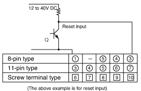
- 2.The input mode and output mode change depending on the DIP switch settings. Therefore, before making any connections, be sure to confirm the operation mode and operation conditions currently set.
- 3.LC4H series counters use a transformerless power supply system, the input equipments must have the power supply transformer in which the secondary side is not grounded with the primary and secondary sides insulated, in order to prevent interference of the power supply circuit when connecting the external input circuit as Fig. A.
Be sure not to use an autotransformer. In case of secondary side grounded or using the autotransformer, this product may be destroyed due to short circuit electrically as Fig. B (1 and 2).
In case of F.G. terminal of equipments such a PLC grounded in secondary side of the transformer, inner circuits of this product and the input equipment may be destroyed due to short circuit electrically as Fig.B (3).
Therefore, use the isolated type counters or do not ground F.G. terminal of the products.
Once the wiring to be used is completely installed and prior to installing this counter, confirm that there is complete insulation between the wires connected to the power terminals (2 each) and the wires connected to each input terminal. If the power and input lines are not insulated, a short-circuit may occur inside the counter and result in internal damage.
In addition, when moving your equipment to a new installation location, confirm that there is no difference in environmental conditions as compared to the previous location.
(except LC4H-S/AC type)

- 4. The input signal is applied by the shorting of each input terminal with the common terminal (terminal (1) for 8-pin types, terminal (3) for 11-pin types and terminal [6] for screw-down terminal types). Never connect other terminals or voltages higher than DC 40 V, because it may destroy the internal devices.
- 5.Transistor output
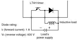
- 1.Since the transistor output is insulated from the internal circuit by a photocoupler, it can be used as an NPN output or PNP (equal value) output. (The above example is 11-pin type)

- 2.Use the diode connected to the output transistor's collector for absorbing the reverse voltage from induced loads.
- 6.When wiring, use shielded wires or metallic wire tubes, and keep the wire lengths as short as possible.
- 7.For the load of the controlled output, make sure that it is lower than the rated control capacity.
4.Output mode setting
The output mode can be set with the DIP switches on the side of the counter. Make the DIP switch settings before installing the counter on the panel.
5.Conditions of usage
- 1.Avoid locations subject to flammable or corrosive gases, excessive dust, oil, vibrations, or excessive shocks.
- 2.Since the cover of the unit is made of polycarbonate resin, avoid contact with or use in environments containing methyl alcohol, benzene, thinners, and other organic solvents; and ammonia, caustic sodas, and other alkaline substances.
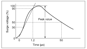
- 3.If power supply surges exceed the values given below, the internal circuits may become damaged. Be sure to use surge absorbing element to prevent this from happening.
| Operating voltage | Surge voltage(peak value) |
|---|---|
| AC type | 6,000V |
| DC type 24V AC type | 1,000V |
Surge wave form
[± (1.2×50) μs uni-polar full wave voltage]
- 4.Regarding external noise, the values below are considered the noise-resistant voltages. If voltages rise above these values, malfunctions or damage to the internal circuitry may result, so take the necessary precautions.
| Power supply terminals | Input terminals | ||
|---|---|---|---|
| AC type | DC type 24V AC type | ||
| Noise voltage | 1,500V | 1,000V | 600V |
Noise wave form (noise simulator)
Rise time : 1ns Pulse width : 1μs,50ns Polarity : ± Cycle : 100 cycles/second- 5.When connecting the operation power supply, make sure that no leakage current enters the counter. For example, when performing contact protection, if set up like that of diagram A, leaking current will pass through C and R, enter the unit, and cause incorrect operation. Diagram B shows the correct setup.

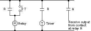
- 6.Long periods of continuous operation in the count-up completed condition (one month or more) will result in the weakening of the internal electrical components from the generated heat and, therefore, should be avoided. If you do plan to use the unit for such continuous operation, use in conjunction with a relay as shown in the circuit in the diagram below.
6.Self-diagnosis functions
If a malfunction occurs, one of the following displays will appear.
| Display | Contents | Output condition | Restoration procedure | Preset values after restoration |
|---|---|---|---|---|
or
| Minimum value went below –999 or –99999. See note 1. | No change | Enter reset or RESET key. | No change |
| Incorrect DIP switch setting. | Restart unit (correct DIP switch settings) | ||
| Malfunctioning CPU. | OFF | Enter reset, RESET key, or restart unit. | The values at start-up before the CPU malfunction occurred. |
| Malfunctioning memory. See note 2. | 0 |
Note 1:
When the counter value goes below the minimum value during any of the subtraction, directive, independent, or phase input modes.
Note 2:
Includes the possibility that the EEPROM’s life has expired.
7.Compliance with the CE marking
When using in applications to which EN61812-1 applies, abide by the following conditions.
Overvoltage category II, pollution level 2
(for sensor type model with power supply)
- 1.This counter employs a power supply without a transformer, so the power and input signal terminals are not insulated.
- 1.When a sensor is connected to the input circuit, install double insulation on the sensor side.
- 2.In the case of contact input, use dualinsulated relays, etc.
- The load connected to the output contact should have basic insulation. This counter is protected with basic insulation and can be double-insulated to meet EN/IEC requirements by using basic insulation on the load.
- Applied voltage should be protected with an overcurrent protection device (example: 250 V 1A fuse, etc.) that conforms to the EN/IEC standards.
- 2.You must use a terminal block or socket for installing the pin-type counter. Do not touch the terminal section or other parts of the timer unit while an electric current is applied. Before installation or removal, confirm that there is no voltage being applied to any of the terminals.
- 3.Do not use this timer with a safety circuit. For example, when using a timer in a heater circuit, etc., provide a protection circuit on the machine side.
Installation methods
1.Surface mount
- 1.For the counters of LC4H series, use the pin type counter.

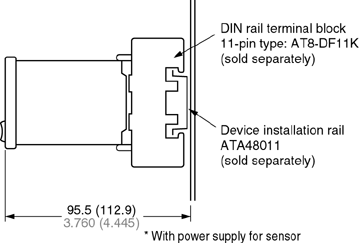
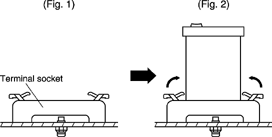
- 2.Put the terminal socket on the board directly or put it on the DIN rail (Fig. 1).
- 3.Insert the counter into the terminal socket and fix it with clip (Fig. 2)
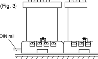
- 4.On DIN rail mounting, mount the counter on the DIN rail tightly to get the proper dimension (Fig. 3).
- 5.8-pin type should be connected with terminal socket AT8-DF8K. 11-pin type should be connected with terminal socket AT8-DF11K.
- 6.DIN rail (AT8-DLA1) is also available (1 m).
2.Flush mount
- 1.For the counters of LC4H series, it is recommended to use the built-in screw terminal type for flush mount. (Mounting frame and rubber gasket are provided when counter is shipped.)

- 2.How to mount the counter
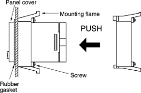
From the panel front, pass the counter through the square hole. Fit the mounting frame from the rear, and then push it in so that the clearance between the mounting frame and the panel surface is minimized. In addition, lock the mounting frame with a screw.
- 3.Caution in mounting the counter
- 1.If the LC4H series are used as the waterproof types (IEC IP66), tighten the reinforcing screws on the mounting frames so that the counters, the rubber gaskets, and the panel surfaces are tightly contacted with each other. (Tighten the two screws with uniform force and make sure that there is no rattling. If the screws are tightened too excessively, the mounting frame may come off.)
- 2.If the counter is installed with the panel cover and the rubber gasket removed, the waterproofing characteristic is lost.
- 4.Removal
Loosen the screws on the mounting frame, spread the edge of frame and remove it.

Pull the mounting frame backward while spreading out its hooks with your thumbs and index fingers

- 5.Correctly connect the terminals while seeing the terminal layout and wiring diagram.
- 6.If the pin type is used, the rear pinbracket (AT8-RR) or the 8P cap (AD8-RC) is necessary to connect the pins. For the 11-pin type, use the 11P cap (AT8-DP11) and avoid directly soldering the round pins on the counter.
- 7.Panel cutout dimensions

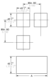
The standard panel cutout dimensions areshown in the left figure.(Panel thickness: 1 to 5 mm .039 to .197inch)
- 8.Although the counters can be mounted adjacent to each other in this case, it is recommended to arrange the mounting holes as shown in the figure to facilitate attaching and detaching the mounting frame.
- 9.Adjacent mounting
Although the counters can be mounted adjacent to each other, remember that the panel surface of LC4H series counter will lose its water-resistant effect. (Panel thickness: 1 to 5 mm .039 to .197 inch)
A=(48×n-2.5)+0.60
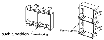
When lining up the counters horizontally, set the frames in such a position so the formed spring areas are at the top and bottom.
When lining up the counters vertically, set the frames in such a position as the formed spring areas are at the right and left.
