Discontinued Products
Lineup
Motor Lineup
Ultra low inertia
| Motor series | Rated output (kW) | Rated rotational speed (Max.speed) (r/min) | Rotary encoder | Brake | Gear | UL/ CSA | Enclosure | Features | |
|---|---|---|---|---|---|---|---|---|---|
| 2500 P/r incremental | 17bit absolute/ incremental | Holding | High precision | ||||||
| MUMA
| 0.05 to 0.4 0.05 0.1 0.2 0.4 | 3000 (5000) | ○ | — | ○ | ○ | ○ | IP65 Except shaft throughhole and connector | Small capacity Ultra low inertia |

Driver Lineup
| Series | Control method | Interface | Safety Function |
|---|---|---|---|
| E Series
| Position control | Pulse input | without |

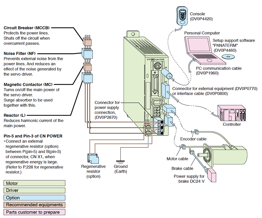
System Configuration
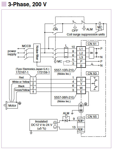
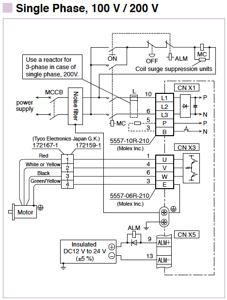
Wiring of main circuit
List of recommended peripheral devices
| Power supply | Motor | Power capacity (at rated output ) | Circuit Breaker (Rated current) | Noise Filter | Magnetic Contactor (Contact Composition) | Wire diameter (L1,L2,L3,U,V and W) | |
|---|---|---|---|---|---|---|---|
| Series | Output | ||||||
| Single phase, 100 V | MUMA | 50 W | 0.3 kVA | 5 A | DV0P4160 | 10 A (3P+1a) | 0.75 mm2 to 0.85 mm2 AWG18 |
| 100 W | 0.4 kVA | ||||||
| 200 W | 0.5 kVA | 10 A | |||||
| Single phase, 200 V | 50 W | 0.3 kVA | 5 A | 15 A (3P+1a) | |||
| 100 W | |||||||
| 200 W | 0.5 kVA | ||||||
| 400 W | 0.9 kVA | 10 A | |||||
| 3-phase 200 V | 50 W | 0.3 kVA | 5 A | 10 A (3P+1a) | |||
| 100 W | |||||||
| 200 W | 0.5 kVA | ||||||
| 400 W | 0.9 kVA | 10 A | |||||
* Select the single and 3-phase common specifications corresponding to the power supplies.
To conform to EC Directives, install a circuit breaker which conforms to IEC and UL Standards (Listed,  marked) between noise filter and power supply.
Remarks
- Use a copper conductor cables with temperature rating of 60 °C or higher for main power connector and ground terminal wiring.
- Use a cable for ground with diameter of 2.0 mm2 (AWG14) or larger.


Wiring/ Connection
- 1.Standard Wiring Example of Main Circuit/ Driver Specifications Encorder Wiring Diagram
- 2.Control Circuit Standard Wiring Example
1. Standard Wiring Example of Main Circuit/ Driver Specifications Encorder Wiring Diagram
Standard Wiring Example of Main Circuit
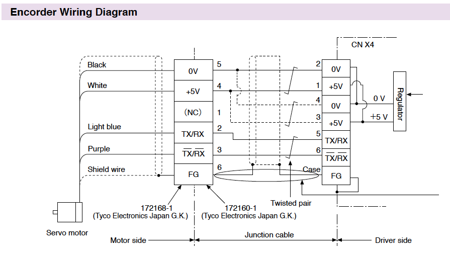
When you make your own junction cable for encoder
1) Refer the wiring diagram.
2) Use the twisted pair wire with shield, with core diameter of 0.18 mm2 (AWG24) or larger, with higher bending resistance.
3) Use the twisted pair wire for the corresponding signal and power supply.
4) Shielding
- Connect the shield of the driver to the case of CN X4.
- Connect the shield of the motor to Pin-6.
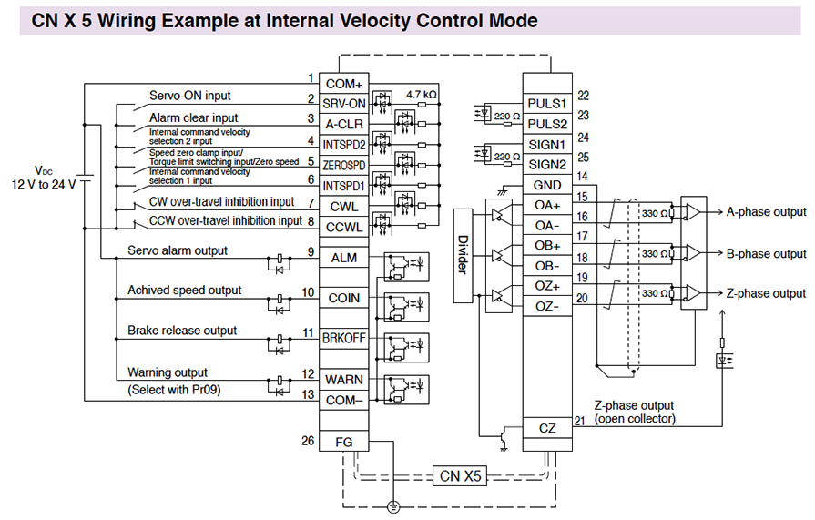
2. Control Circuit Standard Wiring Example
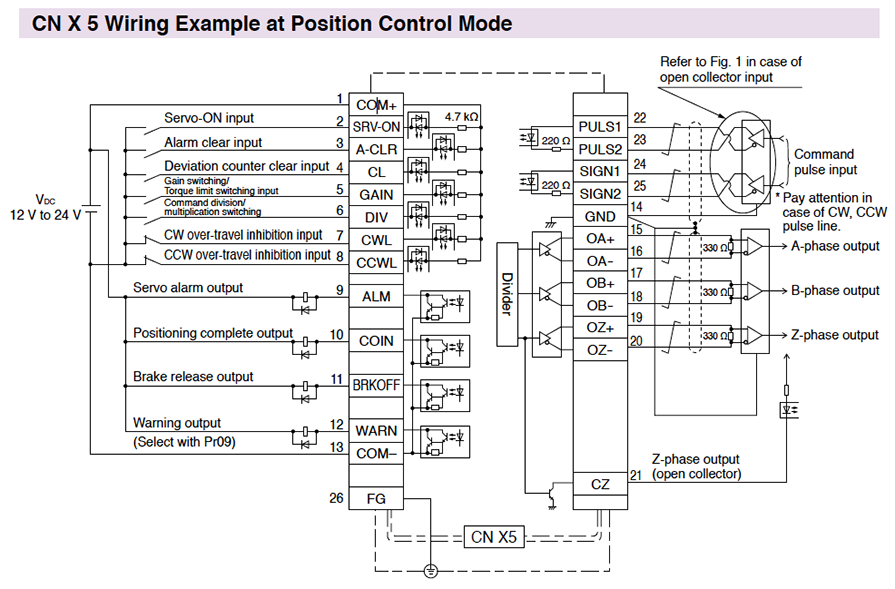
Fig. 1
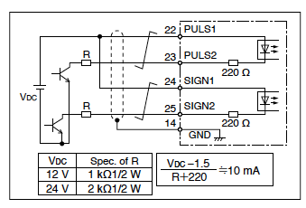
Fig. 1
- This fig. shows the usage of an external control signal power supply.
- You need to install an resistor R for current limit corresponding to VDC.
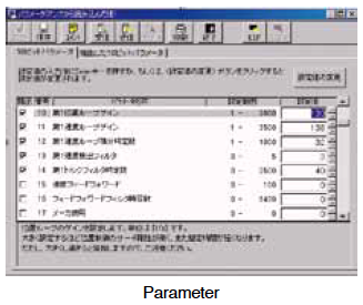
Basic Function
●Parameter setup
- After a parameter is defined on the screen, it will be sent to the driver immediately.
- Once you register parameters you frequently use, they can be easily set up on the screen.
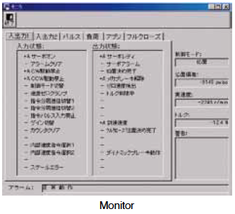
Monitoring Control Conditions
●Monitor
- Control conditions: Control mode, velocity, torque, error and warning
- Driver input signal
・Load conditions: Total count of command/feedback pulses, Load ratio, Regenerative resistor load ratio
●Alarm
- Displays the numbers and contents of the current alarm and up to 14 error events in the past.
- Clears the numbers and contents of the current alarm and up to 14 error events in the past.
Setup
●Auto tuning
- Gain adjustment and inertia ratio measurement
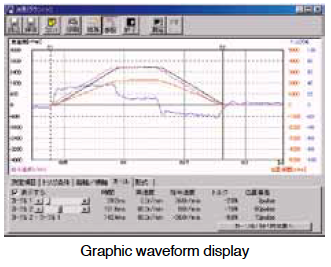
●Graphic waveform display
- The graphic display shows command velocity, actual velocity, torque, and error waveforms.
●Absolute encoder setup
- Clears absolute encoder at the origin.
- Displays single revolution/multi-revolution data.
- Displays absolute encoder status.
Analysis of Mechanical Operation Data
●Frequency analysis
- Measures frequency characteristics of the machine, and displays Bode diagram.
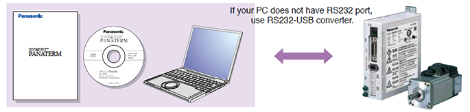
Hardware configuration
[Personal computer]
- CPU : Pentium 100MHz or more
- Memory : 16 MB or more (32 MB recommended)
- Hard disk capacity (vacancy of 25 MB or more recommended)
- OS : Windows® 98, Windows® Me, Windows® 2000, Windows® XP (US version)
- Communication speed of serial communication port : 2400 bps or more (The software may not operate normally using USB-to-Serial adapter.)
[Display]
- Resolution : 640*480 (VGA) or more (desirably 1024*768)
- Number of colors : 256 colors or more
[CD-ROM drive]
CD-ROM drive operable on the above-mentioned personal computer