Basic Information
Realtime Express (RTEX)
Advanced Network to realize high-precise real-time performance for Servo Control


-
*1 Multifunctional type, Application specialized type
*2 Standard type

| Type | Series | Position Control | Speed Control | Torque Control | Full closed Control | External Scale | Safety Connector | Sensor Feedback | |
|---|---|---|---|---|---|---|---|---|---|
| Rotation type | Standard type | A7NE | |||||||
| Multifunctional type | A7NF | ||||||||
| Application specialized type | A7NR* |
*Specification-based product (Subject to customer evaluation)
*Realtime Express and RTEX are registered trademarks of Panasonic Holdings Corporation.
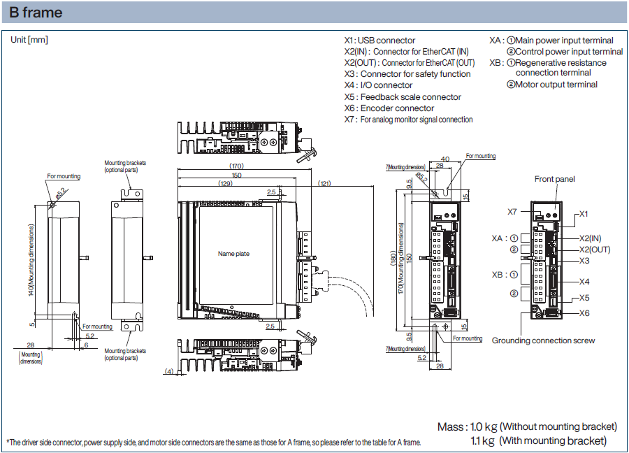
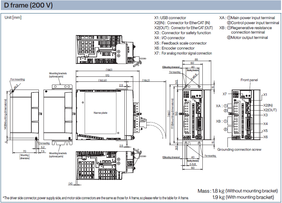
A7N Series (Driver: B frame, Motor: 200 W)

<Caution>
Please select the appropriate tightening torque for the product's mounting screws, taking into consideration the strength of the screws used and the material to which they are attached, to avoid loosening or damage.
Example) When tightening steel screws (M5) to steel, 2.7 N•m to 3.3 N•m.
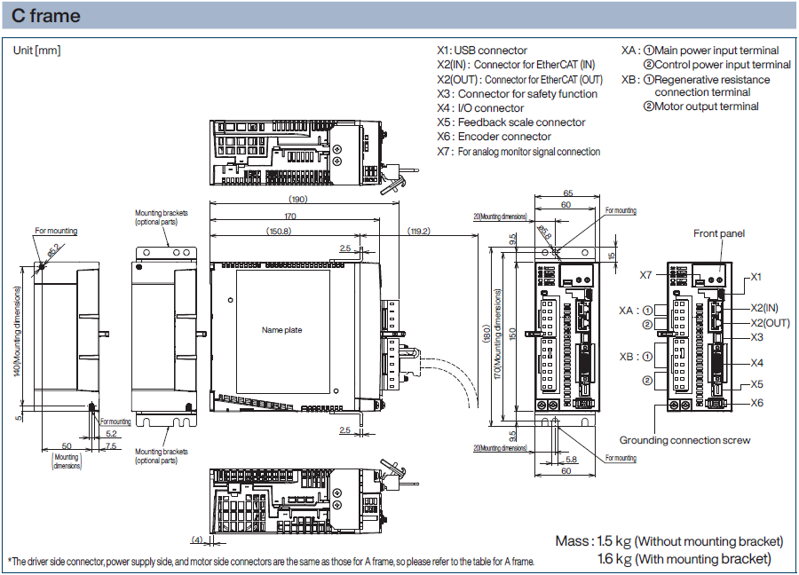
List of applicable peripherals
| Driver | Applicable motor | Voltage specification (V) *1 | Rated output (W) | Power supply capacity (at rated load) (kVA) | Circuit breaker (Rated current) (A) | Short circuit protection element (Fuse) (A) | Noise filte (Single Phase/Three Phase) | Ferrite core | Electromagnetic contactor (A) *2 | Conductor thickness for main circuit Withstand voltage | Terminal block crimp terminal for main circuit *3 | Wire thickness for control power supply | Terminal block crimp terminal for control power supply | Motor wire thickness Withstand voltage *6 | Terminal block crimp terminal for motor *4 | Brake wire thickness Withstand voltage *6 | |
|---|---|---|---|---|---|---|---|---|---|---|---|---|---|---|---|---|---|
| Main circuit power input line | Control circuit power input line | ||||||||||||||||
| MADN | MSMG MHMG | Single Phase 100 | 50 | Approx.0.4 | 15 | 10 | 1 | DV0P4170 (Single phase only) | DV0P1460 | 20 (3P+1a) | 2.0 mm2/ AWG14 300 VAC or more | Connecting to a dedicated connector | 2.0 mm2/ AWG14 300 VAC or more | Connecting to a dedicated connector | 0.75 mm2/ AWG18 to 2.0 mm2/ AWG14 300 VAC or more | Connecting to a dedicated connector | 0.3 mm2/ AWG22 to 0.75 mm2/ AWG18 100 VAC or more |
| 100 | |||||||||||||||||
| MBDN | 200 | Approx.0.5 | |||||||||||||||
| MCDN | 400 | Approx.0.9 | 20 | DV0PM20042 | |||||||||||||
| MADN | Single Phase/Three Phase 200 | 50 | Approx.0.5 | 10 | DV0P4170 (Single phase only))/ DV0PM20042 | ||||||||||||
| 100 | |||||||||||||||||
| 200 | Approx.0.6 | ||||||||||||||||
| MBDN | 400 | Approx.1.0 | |||||||||||||||
| MCDN | 750 | Approx.1.9 | 20 | DV0PM20042 | |||||||||||||
| MHMG MDMG MGMG MHMG | 850 | Approx.2.4 | DV0P4220 | 32 (3P+1a) | |||||||||||||
| 1000 | |||||||||||||||||
| MDDN *5 | 1000 | 35 | |||||||||||||||
| 1300 | Approx.2.9 | ||||||||||||||||
| 1500 | |||||||||||||||||
*1 For single phase/three phase 200 V common specifications, select peripheral equipment according to the power supply used.
*2 The electromagnetic contactor used for the external dynamic brake resistor should have the same rating as the electromagnetic contactor used for the main circuit.
*3 Use the same crimp terminal for the ground screw as the crimp terminal for the main circuit terminal block.
*4 Make sure that the thickness of the ground wire and the external dynamic brake resistor wire are the same or larger than the motor wire.
*5 For UL certification, in the case of a single phase power supply, please use a clamp meter that can measure the effective value current and derate the input effective current to 12A or less.
*6 Applicable wire size varies depending on the motor model number. Please check the instruction manual or specifications document for the applicable wire size for each motor model number.
* Specifications are subject to change due to improvements, etc. Please be sure to obtain the latest information when using these products.
● Circuit breakers and electromagnetic contactors
To comply with EU directives/UK standards, be sure to connect an IEC standard and UL certified (LISTED, marked) molded circuit breaker between the power supply and the noise filter.
Make sure that the short-circuit current of the power supply you use is less than 5000 Arms symmetrical current when the product’s maximum input voltage is less than that. If the short-circuit current of the power supply exceeds this, install a currentlimiting device (current-limiting fuse, current-limiting breaker, transformer, etc.) to limit the short-circuit current.
<Caution>
• Select a molded circuit breaker and noise filter with a capacity commensurate with the power supply capacity (taking load conditions into consideration).
● Terminal block and protective ground terminal
• Use copper conductor wires with a temperature rating of 75 °C or higher for wiring.
• For frames A to D, use the included dedicated connectors. In that case, keep the length of the stripped wire between 8 mm and 9 mm.
| Driver external frame symbol | Ground screw | Connector to upper controller (X4) | ||
|---|---|---|---|---|
| Call | Tightening torque (N・m) Note)1 | Call | Tightening torque (N・m) Note)1 | |
| MADN, MBDN, MCDN, MDDN | M4 | 0.7 to 0.8 | M2.6 | 0.2±0.05 |
Note)1
<Caution>
• Exceeding the maximum tightening torque may cause damage.
• Do not turn on the power while the terminal block screws are loose.
• Turning the power on while the screws are loose may cause smoke or fire.
<Remarks>
• Check the tightening torque periodically once a year for looseness.
| Item | Performance | |||
|---|---|---|---|---|
| Input power | 100 V series | Main circuit power supply | Single phase 100 to 120 V, -15% to +10%, 50/60 Hz | |
| Control circuit power supply | Single phase 100 to 120 V, -15% to +10%, 50/60 Hz | |||
| 200 V series | Main circuit power supply | A frame to D frame | Single phase/3-phase 200 to 240 V, -15% to +10%, 50/60 Hz | |
| Control circuit power supply | A frame to D frame | Single phase 200 to 240 V, -15% to +10%, 50/60 Hz | ||
| Ambient conditions of use | Temperature | Operating temperature: 0 to 60 °C (Can be used at reduced rating if 55 to 60 °C) (No freezing) Storage temperature: -20 to 65 °C (Maximum temperature guaranteed: 80 °C, 72 hours, non-condensing *1) | ||
| Humidity | Use, Storage Humidity: 20 to 85% RH or Less (No Condensation *1) | |||
| Elevation | Below 2000 m above sea level (can be used with reduced rating for 1000 to 2000 m) | |||
| Vibration | 5.88 m/s2 or less, 10 to 60 Hz | |||
| Degree of contamination | Degree of contamination 2 | |||
| Mounting space | 10 mm or more (1 to 10 mm can be used with reduced rating *2) | |||
| Protection class | IP00 | |||
| Insulation voltage | Withstand AC1500V for 1 minute between 1st side and earth | |||
| Control method | IGBT PWM method Sine wave drive | |||
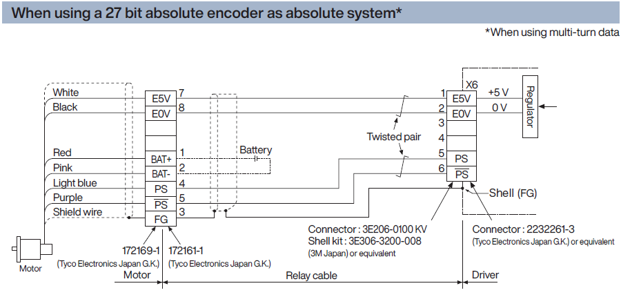
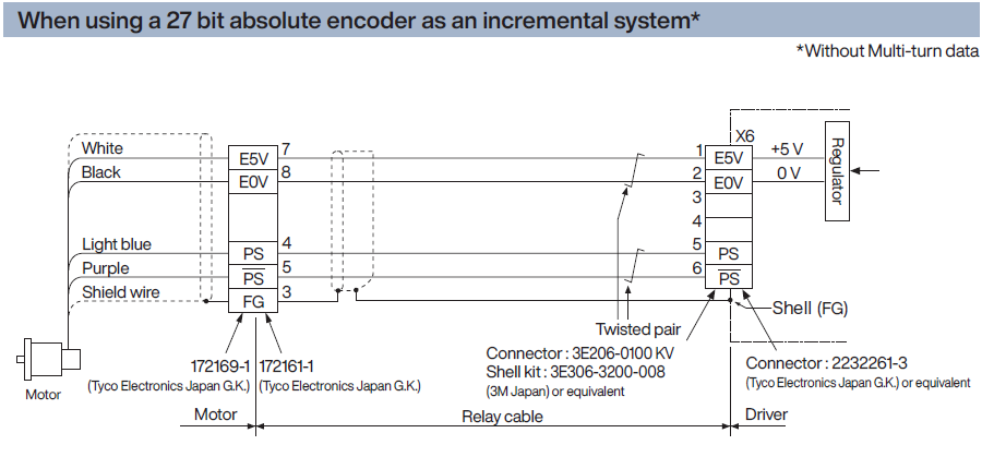
| Encoder feedback | 27 bit (134217728 resolution) 7-wire serial absolute encoder | |||
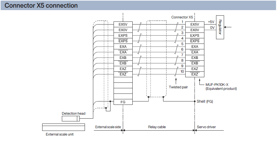
| External scale feedback*3 | A/B phase/home signal differential input type Panasonic industry serial communication type*4 | |||
| Control signal | Input | General purpose 8 inputs General-purpose input functions are selected by parameters | ||
| Output | General purpose 3 outputs General-purpose output functions can be selected by parameters | |||
| Analog signal | Input | 1 input (16-bit A/D : input) *5 | ||
| Output | 2 outputs (Analog monitor 1, Analog monitor 2) | |||
| Pulse signal | A/B phase output (2 outputs) | Line driver output with A/B phase signal | ||
| Communication function | Realtime Express (RTEX) | Real-time operation command transmission, parameter setting, status monitoring, etc. possible | ||
| USB | Parameter settings, status monitoring, etc. possible by connecting a PC, etc. | |||
| Safety function*3 | Safe Torque Off (STO) 2 Input (Safety Input 1, 2) 1 Output (EDM output) | |||
| Front panel | ① Rotary switch ② LED 7 segment 2 digits and 4 lights for status display ③ Connector for analog monitor | |||
| Regenerative | A, B frame: No built-in regenerative resistor (external only) C, D frame: Built-in regenerative resistor (external connection is also possible) | |||
| Dynamic brake | Frame A-D: Built-in | |||
| Control mode | Position control: cyclic position control (CP) | |||
*1 Please note that condensation is more likely to occur as the temperature drops.
*2 When using the servo driver at an ambient temperature of 55 to 60 °C or at an altitude of 1000 to 2000 m, use the load factor multiplied by the respective load factors shown in the figure on the right. When using a servo driver with a mounting interval of 1 to 10 mm, refer to the ambient temperature shown in the figure on the right.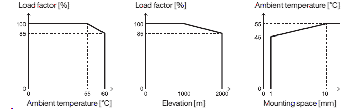
*3 Not available for standard types.
*4 Please refer to the separate collaboration catalog for compatible scale manufacturers and product numbers.
*5 Available for only applicaton specialized type. (Specification-based product (Subject to customer evaluation))

Connection of the regenerative resistor
| Frame type | Short line | Built-in regenerative resistor | Connector XB connection: | |
|---|---|---|---|---|
| When using an external regenerative resistor | When an external regenerative resistor is not used | |||
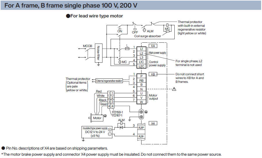
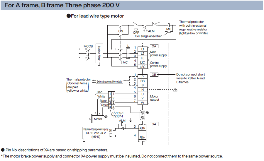
| A frame B frame | None | None | Between P and B: Connect external regenerative resistor | Between P and B: Always open |
Note)1
| Frame type | Short wire (Accessory) | Built-in regenerative resistor | Connector XB connection: | |
|---|---|---|---|---|
| When using an external regenerative resistor | When an external regenerative resistor is not used | |||
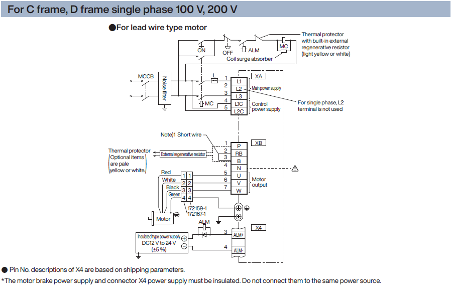
| C frame D frame | Yes | Yes | Remove the attached short line between RB and B. Between P and B: Connect external regenerative resistor | Short circuit with attached short wire between RB and B |
A safety circuit that controls safety functions is made by connecting the host controller. If you do not want to construct a safety circuit, please use the included safety bypass plug.
Safety Torque Off (STO) Function Overview
The Safe Torque Off (STO) function uses a safety input signal to forcibly turn off the drive signal of the power transistor inside the servo driver using a circuit (hardware) to cut off the motor current and output torque.
When the STO function is activated, the servo driver turns off the servo ready output signal (S-RDY) and enters the STO state, and "St" is displayed on the front panel. Also, when the STO input is released and the Servo-On input is turned off (OFF), the state automatically transitions to the Servo-Off state.
Safety precautions
- If there is an external force (such as gravity on a vertical axis), the motor will move. If holding is required, use a separate external brake or other means. Please note that the brake of a servo motor with a brake is only for holding and cannot be used for braking purposes.
- Furthermore, even if there is no external force, if parameter Pr5.10 "Sequence at alarm" is set to free run (dynamic brake disabled), the motor will free run and the stopping distance will be longer. Please do not let this become a problem.
- Even when the STO function is working, the following dangers still exist, so be sure to consider safety in your risk assessment. Incorrect use may result in personal injury.
- If there is an external force (such as gravity on a vertical axis), the motor will move. If holding is required, use a separate external brake or other means. Please note that the brake of a servo motor with a brake is only for holding and cannot be used for braking purposes.
- Due to a power transistor failure, etc., the motor may move within a range of up to 180 electrical degrees. Please do not let this become a problem.
- The STO function cuts off power to the motor, but does not cut off power to the servo driver and does not provide electrical isolation. When performing maintenance on the servo driver, take other measures such as cutting off the power to the servo driver.
- EDM output signals are not safety outputs. Do not use it for any purpose other than the failure monitoring function. Incorrect use may result in personal injury.
- The STO status monitor output signal is not a safety-related part. When designing the system, make sure to avoid dangerous conditions even if the STO condition monitor output signal cannot be output normally. Incorrect use may result in personal injury.
- The dynamic brake and external brake release signal outputs are not safety-related parts. Make sure that the system design avoids dangerous conditions even if the external brake release fails during STO conditions. Incorrect use may result in personal injury.
- When using the STO function, connect equipment that complies with safety standards. Use of equipment that does not meet safety standards may result in personal injury.
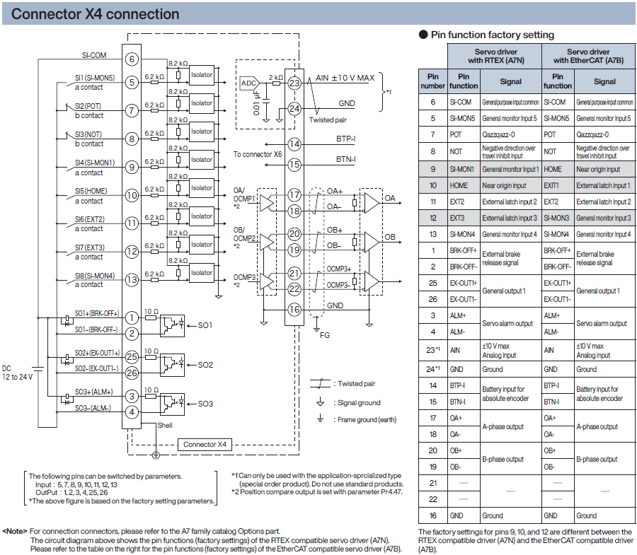
[Pin arrangement]
(View from the cable side)

*Do not connect anything to the NC.
●System configuration example