Basic Information
Swifter, smarter and easier to use
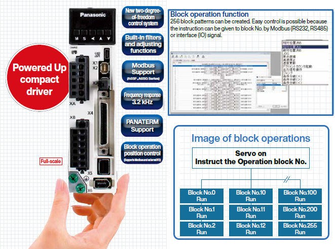
Powered Up compact driver


-
※1 A6SF Series
※2 A6SE, A6SG Series
Features
Swifter, smarter and easier to use
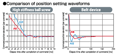
High-speed response, high-precision positioning for quick and accurate movement
Our proprietary algorithm in addition to upgraded CPU and other hardware realized further high-speed response. Furthermore, high-precision positioning is achieved by automatically eliminating micro vibrations and machine oscillation caused by the resonance.
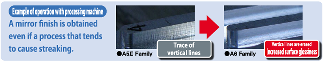
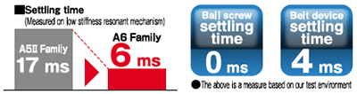
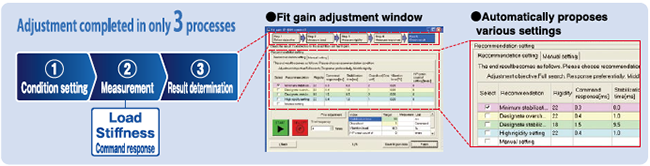
Easy and quick setting, shortening conventional settling time by approx. 64%*1.
Newly developed fit gain function substantially reduces adjustment time. Adaptive notch filter and various gains can be automatically set and adjusted.
*1 Comparison with conventional product A5Ⅱ Family
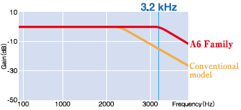
Realized 3.2 kHz frequency response to improve productivity.
Realizes 3.2 kHz frequency response. At 139% that of conventional models*1, it enables hjgh-speed operation and improves productivity.
*1 Comparison with conventional product A5Ⅱ Family
Lifespan diagnosis / degradation diagnosis
It warns expected lifetime of the motor & driver, and deterioration limit of the equipment.
Other driver functions
Adaptive load control
Adaptive load control automatically sets the best suitable gain table in response to fluctuations in inertia caused by changes in workload, thus keeping machines operating stably at all times.

Friction torque compensation
This function reduces the effect of machine related friction and improves responsiveness. Three kinds of friction compensation can be set: unbalanced load compensation, which sets an offset torque that is constantly applied; kinetic friction compensation, which changes direction in response to the direction of movement; and viscous friction compensation, which changes according to the speed command.
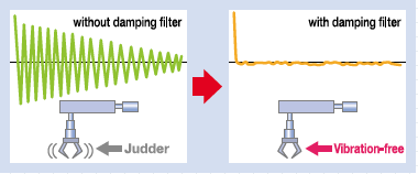
Manual/Auto damping filter
Equipped with a damping filter that is automatically set through the setup support software. This filter removes the natural vibration frequency component from the command input, greatly reducing vibration of the axis when stopping. The number of filters for simultaneous use has been increased to three from the conventional two filters. (Two from one in the two-degree-of-freedom-control mode.) The adaptive frequency has also been significantly expanded from 0.5 Hz to 300 Hz.
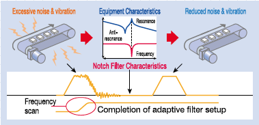
Manual/Auto notch filter
Equipped with auto-setting notch filters for greater convenience.
Now there is no need to measure troublesome vibration frequencies. Our notch filters automatically detect vibration and provide simple auto-setting.
These notch filters greatly reduce noise and vibration caused by equipment resonance and respond quickly.
The A6 Family is equipped with 5 notch filters with frequencies settable from 50 Hz to 5000 Hz. Depth can be individually adjusted within this range. (Two of the filters share automatic settings.)
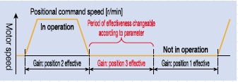
3-Step gain
A 3-step gain switch is available in addition to the normal gain switch.This chooses appropriate gain tunings at both stopping and running. The 3-step gain switch gives you choices of 3 different tunings for normal running, stopping for faster positioning and at stopping. The right gaining tunings achieve lower vibration and quicker positioning time of your application.
Inertia ratio conversion
You can adjust right inertia ratio by Inertia ratio conversion input (J-SEL) of interface. When you have significant load inertia changes,it can adjust unbalanced speed and position gain turning combination.It ends up quicker response of your system.
Input/output signal assignment
You can use the parameters to arbitrarily allocate the universal 10 inputs and 6 outputs. (Inputs can be selected as either A contacts or B contacts). The Panaterm setup software provides an exclusive screen for a more simplified setup.
Torque limiter switching
These can be used for applications such as simplified pressure, tension control, and sensor-less homing.
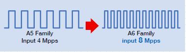
Supports semi-/full-closed loop (8 Mpps input pulse, 4 Mpps output pulse) control.
Supports full-closed loop control. The A6SF series accommodates a command input of 8 Mpps and feedback output of 4 Mpps, enabling high-resolution, high-speed operation. Supports the industry's leading positioning resolution commands (pulse-train commands).
●The A6SE and A6SG series do not support full-closed loop control.
●Applicable scale: AB-phase feedback scale (general purpose product) and serial feedback scale (compatible with our exclusive format)
Dynamic braking
With parameter settings, you can select dynamic braking, which shorts servomotor windings U, V and W at Servo-OFF, during positive direction/ negative direction, and during power shutdown and tripping of the circuit breaker for over travel inhibition.
●The desired action sequence can be set up to accommodate your machine requirements.
Inrush current preventive function
This driver is equipped with a rush current preventive resistor to prevent the circuit breaker from shutting off the power supply as a result of inrush current occurring at power-on.
Parameter initialization
Using the front panel or by connecting a PC, you can restore the parameters to the factory settings.
Regenerative energy discharge
A regenerative resistor is used to discharge regenerative energy, which is the energy generated when stopping a load with a large moment of inertia or when using this unit in vertical operation. This energy is returned to the driver from the motor.
● Frame A, and frame B model drivers do not contain a regenerative resistor. Optional regenerative resisters are recommended.
● Frame C to frame F model drivers contain one regenerative resistor; however, adding an optional regenerative resistor provides additional regeneration capability.
Multifunctional software for quick adjustment support
PANATERM set-up support software
The PANATERM set-up support software, with many added features. The PANATERM assists users in setting parameters, monitoring control conditions, setup support, and analyzing mechanical operation data on the PC screen, when installed in a commercially available personal computer, and connected to the MINAS A6 Family through the USB interface. Choose either English, Japanese, Chinese, Korean-language display.
Click here for more information.Lineup
Driver Lineup
| Series | Position control | Block op | Speed control | Internal velocity command | Torque control | Full-close control | Pulse | Analog | Modbus | External scale | RS232 RS485 | STO* | Voltage (V) | Rated output (W) | ||
|---|---|---|---|---|---|---|---|---|---|---|---|---|---|---|---|---|
| Analog/ Pulse/ Modbus | Rotary Motor | A6SE |
|
|
|
| AC100/ AC200 | 50 to 2200 | ||||||||
| A6SG |
|
|
|
|
|
| AC100/ AC200 | 50 to 2200 | ||||||||
| A6SF |
|
|
|
|
|
|
|
|
|
|
|
| AC100/ AC200/ AC400 | 50 to 2200 | ||

* STO: Safety Torques Off
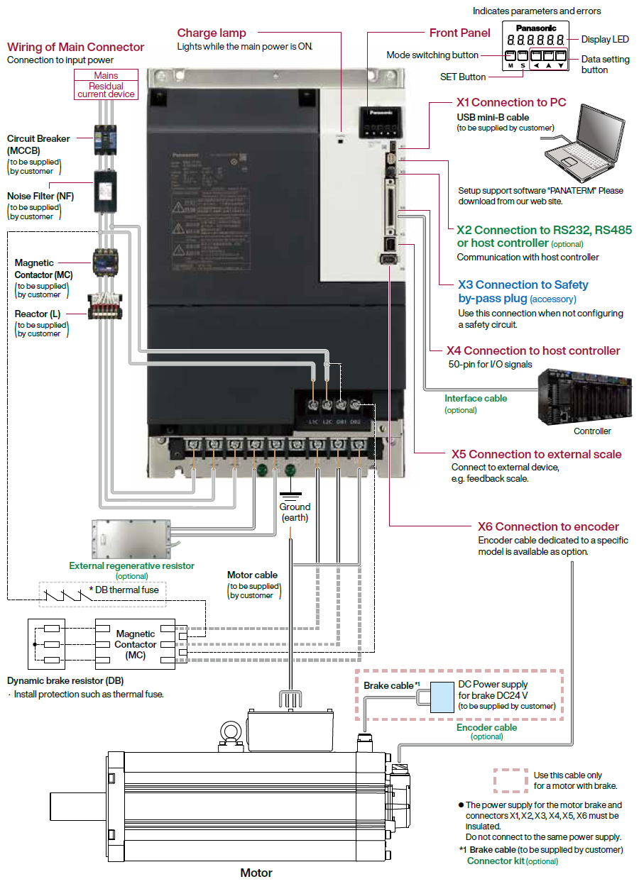
System Configuration
Overall Wiring
A6 SF Series (Driver: A-frame Motor: 200 W)
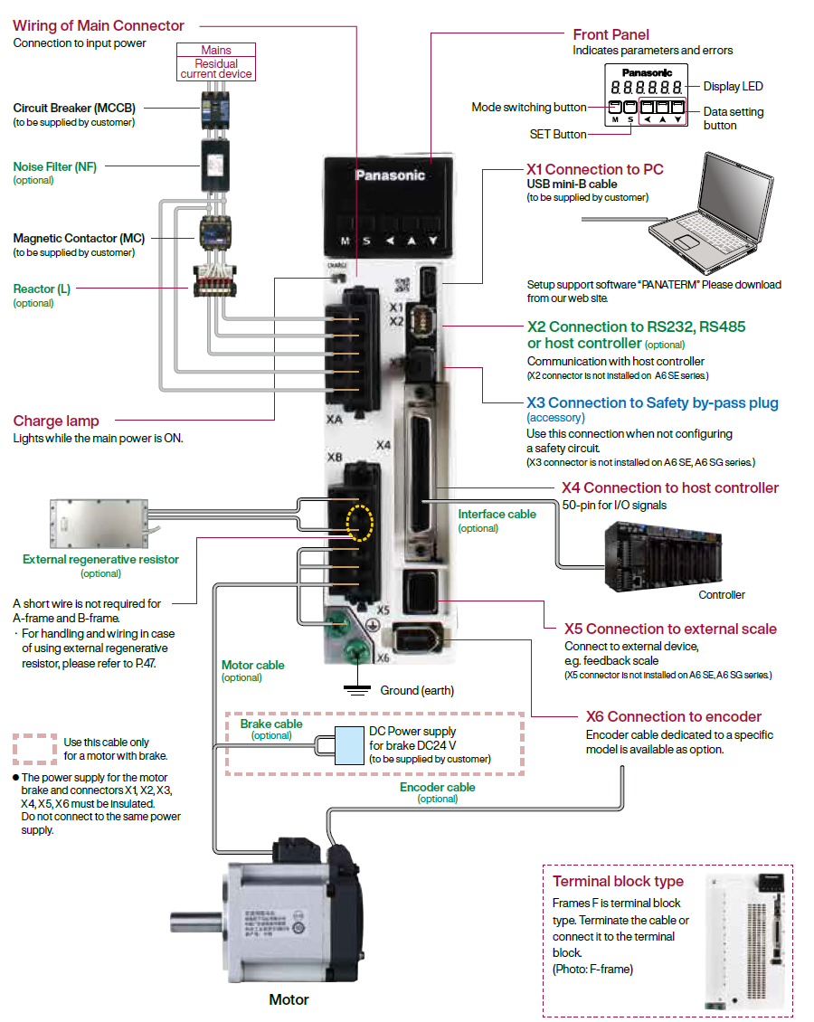
Apply adequate tightening torque to the product mounting screw by taking into consideration strength of the screw and the characteristics of material to which the product is installed. Overtightening can damage the screw and/or material; undertightening can result in loosening.
Example) Steel screw (M5) into steel section: 2.7 N·m to 3.3 N·m.
A6 SG Series/ A6 SE Series (Driver: D-frame Motor: 1.0 kW)
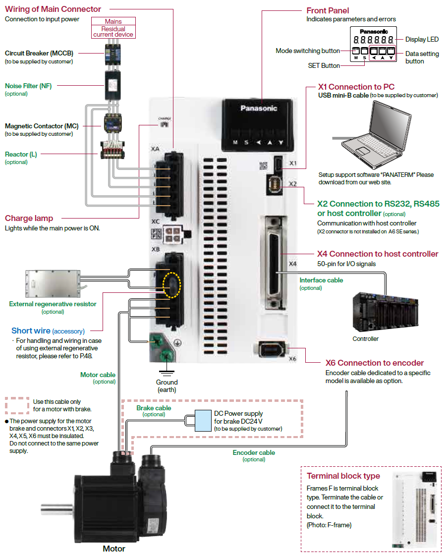
Initial setup of rotational
direction:positive = CCW and negative = CW.
Pay an extra attention.

A6SF Series (Driver: G-frame Motor: 7.5 kW)
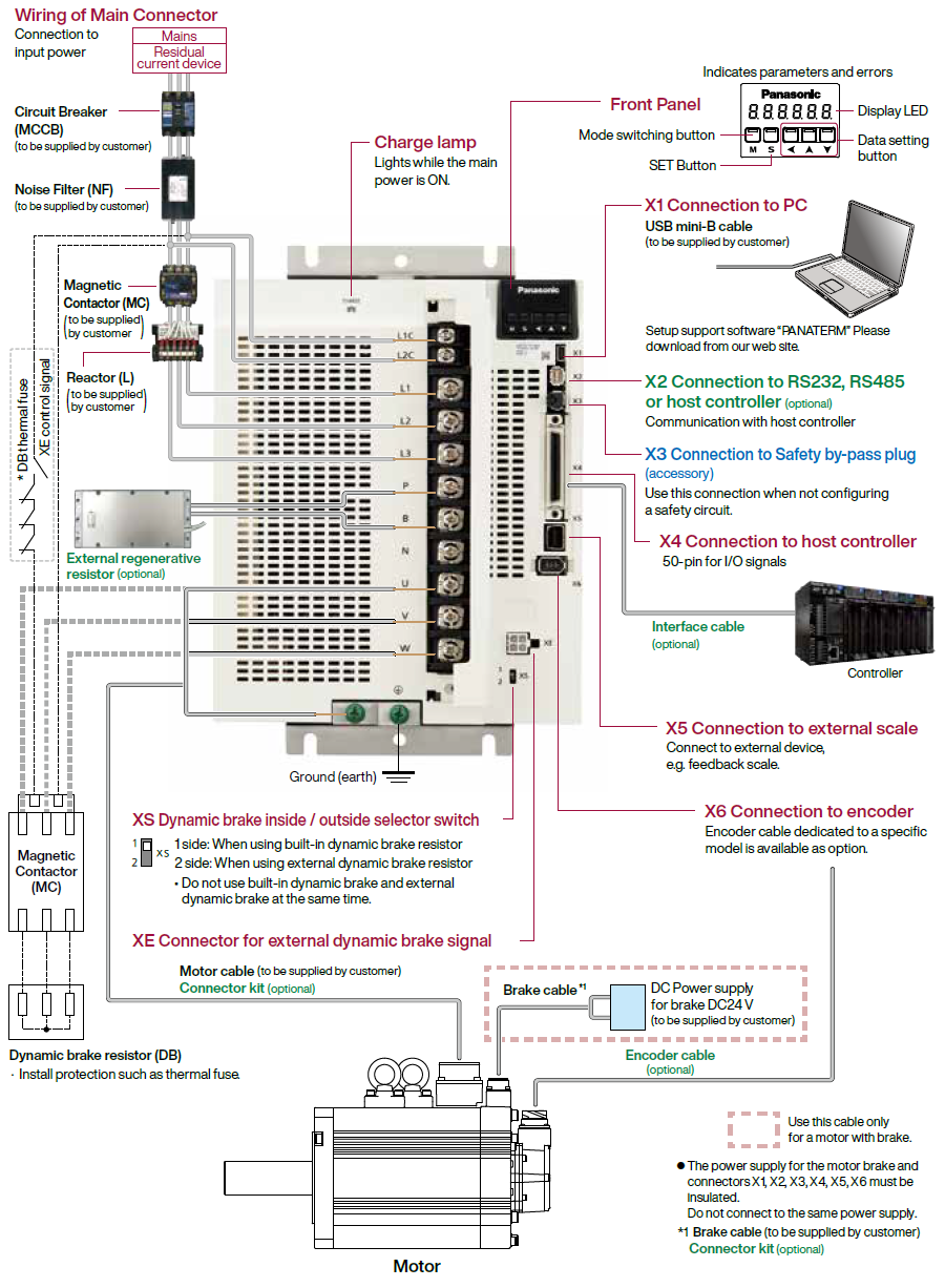
Apply adequate tightening torque to the product mounting screw by taking into consideration strength of the screw and the characteristics of material to which the product is installed. Overtightening can damage the screw and/or material; undertightening can result in loosening.
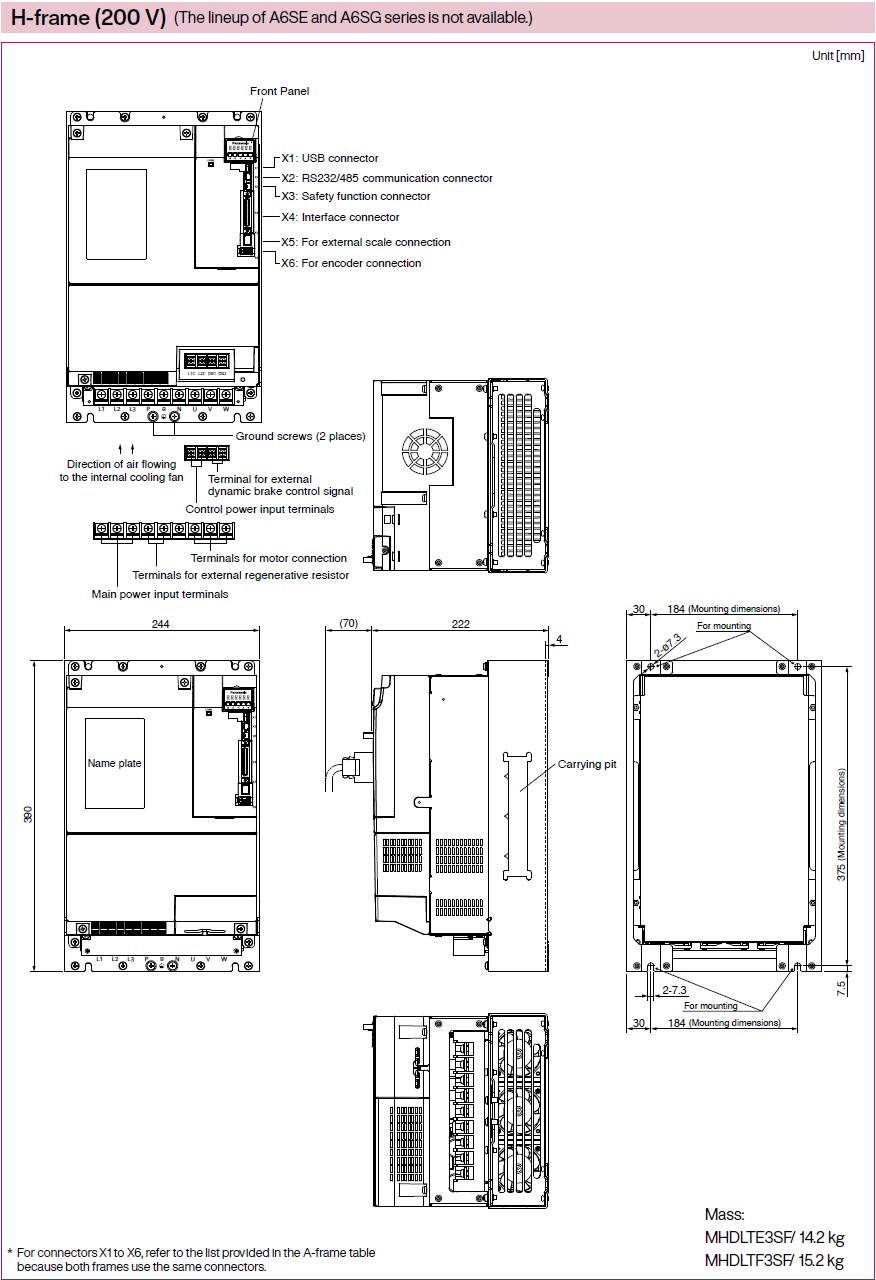
A6SF Series (Driver: H-frame Motor: 22.0 kW)
Initial setup of rotational direction:
positive = CCW and negative = CW.
Pay an extra attention.
Driver and List of Applicable peripheral devices
| Driver | Applicable motor | Voltage (V) *1 | Rated output (kW) | Required Power ( at the rated load) (kVA) | Circuit breaker rated (rated current) (A) | Noise filter (Single phase/ 3-phase ) | Surge absorber (Single phase/ 3-phase ) | Ferite core | Rated operating current of magnetic (contactor contact configuration ) *2 | Diameter and withstand voltage of main circuit cable | Crimp terminal for main circuit terminal block *3 | Diameter and withstand voltage of control power supply cable | Crimp terminal for control power supply terminal block | Diameter and withstand voltage of motor cable *4 | Diameter and withstand voltage of brake cable |
|---|---|---|---|---|---|---|---|---|---|---|---|---|---|---|---|
| MADL | MSMF MHMF | Single phase, 100 | 0.05 | approx. 0.4 | 10 | DV0P4170 | DV0P4190 | DV0P1460 | 20 A (3P+1a) | 0.75 mm2/ AWG18 600 VAC or more to 2.0 mm2/ AWG14 600 VAC or more | Connection to exclusive connector | 0.75 mm2/ AWG18 600 VAC or more | Connection to exclusive connector | 0.75 mm2/ AWG18 600 VAC or more to 2.0 mm2/ AWG14 600 VAC or more | 0.28 mm2 to 0.75 mm2/ AWG22 to AWG18 100 VAC or more |
| MSMF MQMF MHMF | 0.1 | ||||||||||||||
| MSMF MHMF | Single/ 3-phase 200 | 0.05 | approx. 0.5 | DV0P4170/ DV0PM20042 | DV0P4190/ DV0P1450 | ||||||||||
| MSMF MQMF MHMF | 0.1, 0.2 | ||||||||||||||
| MBDL | MSMF MQMF MHMF | Single phase, 100 | 0.2 | DV0P4170 | DV0P4190 | ||||||||||
| Single/ 3-phase 200 | 0.4 | approx. 0.9 | DV0P4170/ DV0PM20042 | DV0P4190/ DV0P1450 | |||||||||||
| MCDL | MSMF MQMF MHMF | Single phase, 100 | 0.4 | approx. 0.9 | 15 | DV0PM20042 | DV0P4190 | ||||||||
| MSMF MHMF | Single/ 3-phase 200 | 0.75 | approx. 1.8 | DV0P4190/ DV0P1450 | |||||||||||
| MDDL | MGMF | Single/ 3-phase 200 | 0.85 | approx. 2.0 | 20 | DV0P4220 | DV0P4190/ DV0P1450 | 30 A (3P+1a) | 0.75 mm2/ AWG18 100 VAC or more | ||||||
| MSMF | 1.0 (80 mm sq.) | approx. 2.4 | |||||||||||||
| MDMF MHMF | 1.0 | ||||||||||||||
| MHMF | 1.0 (80 mm sq.) | ||||||||||||||
| MSMF | 1.0 | ||||||||||||||
| MGMF | 1.3 | approx. 2.6 | |||||||||||||
| MSMF MDMF MHMF | 1.5 | approx. 2.9 | |||||||||||||
| MEDL | MGMF | 3-phase 200 | 1.8 | approx. 3.4 | 30 | DV0PM20043 | DV0P1450 | DV0P1460 | 60 A (3P+1a) | 2.0 mm2/ AWG14 600 VAC or more to 3.5 mm2/ AWG12 600 VAC or more | 2.0 mm2/ AWG14 600 VAC or more to 3.5 mm2/ AWG12 600 VAC or more | ||||
| MSMF MDMF MHMF | 2.0 | approx. 3.8 | |||||||||||||
| MGMF | 2.4 | approx. 4.5 | 3.5 mm2/ AWG12 600 VAC or more | ||||||||||||
| MFDL | MGMF | 3-phase 200 | 2.9 | approx. 5.0 | 50 | DV0P3410 | DV0P1450 | 3.5 mm2/ AWG12 600 VAC or more |
Terminal block M5 |
Terminal block M5 | |||||
| MSMF MDMF MHMF | 3.0 | approx. 5.2 | |||||||||||||
| MSMF MDMF MHMF | 4.0 | approx. 6.5 | 100 A (3P+1a) | ||||||||||||
| MGMF | 4.4 | approx. 7.0 | |||||||||||||
| MSMF MDMF MHMF | 5.0 | approx. 7.8 | |||||||||||||
| MGDL | MGMF | 3-phase 200 | 5.5 | approx. 8.5 | 60 | HF3080C-SZA (Recommended components ) | DV0P1450 | DV0P1460 RJ8095 (Recommended components ) T400-61D *5 | 100 A (3P+1a) | 8.0 mm2/ AWG8 600 VAC or more |
Terminal block M3 | 14 mm2/ AWG6 600 VAC or more | 0.75 mm2/ AWG18 100 VAC or more | ||
| MDMF | 7.5 | approx. 11 | |||||||||||||
| MHMF | |||||||||||||||
| MHDL | MDMF | 3-phase 200 | 11.0 | approx. 15 | 125 | HF3100C-SZA (Recommended components ) | DV0P1450 | 150 A (3P+1a) | 22 mm2/ AWG4 600 VAC or more |
Terminal block M6 |
Terminal block M4 | 22 mm2/ AWG4 600 VAC or more *6
Terminal block M8 | |||
| 15.0 | approx. 20 | ||||||||||||||
| 22.0 | approx. 28 | 175 | 38 mm2/ AWG2 600 VAC or more |


*1 Select peripheral devices for single/3phase common specification according to the power source.
*2 The magnetic contactor used for the external dynamic brake resistor should have the same rating as the magnetic contactor used for the main circuit.
*3 For the ground screw, use the same crimp terminal as that for the main circuit terminal block.
*4 The thickness of the grounding wire and the thickness of the external dynamic brake resistor should be the same as or larger than the thickness of the motor wire.
*5 Please use all to comply with international standards.
*6 22.0 kW The connection of the motor power line is a terminal block. In order to comply with the CSA standard, it is necessary to use a CSA standard-certified power wire round terminal.
● About circuit breaker and magnetic contactor
To comply to EC Directives, install a circuit breaker between the power and the noise filter without
fail, and the circuit breaker should conform to IEC Standards and UL recognized (Listed and marked).
Suitable for use on a circuit capable of delivering not more than 5000 Arms symmetrical amperes, below the maximum input voltage of the product.
If the short-circuit current of the power supply exceeds this value, install a current limit device (current limiting fuse, current limiting circuit breaker, transformer, etc.) to limit the short-circuit current.
[Caution]
- Select a circuit breaker and noise filter which match to the capacity of power supply (including a load condition).
● Terminal block and protective earth terminals
- Use a copper conductor cables with temperature rating of 75 ℃ or higher.
- Use the attached exclusive connector for A-frame to E-frame, and maintain the peeled off length of 8 mm to 9 mm.
■Fastening torque list (Terminal block screw/Terminal cover fastening screw)
| Driver | Terminal block screw | Terminal cover fastening screw | |||
|---|---|---|---|---|---|
| Frame | Terminal name | Nominal size | Fastening torque (N·m) Note)1 | Nominal size | Fastening torque (N·m) Note)1 |
| MFDL | MFDL L1, L2, L3, L1C, L2C, P, RB, B, N, U, V, W | M5 | 1.8 to 2.0 | M3 | 0.19 to 0.21 |
| MGDL | L1C, L2C | M4 | 0.4 to 0.6 | M3 | 0.19 to 0.21 |
| L1, L2, L3, P, B, N, U, V, W | M5 | 2.0 to 2.4 | |||
| MHDL | L1C, L2C, DB1, DB2 | M4 | 0.7 to 1.0 | M5 | 2.0 to 2.5 |
| L1, L2, L3, P, B, N, U, V, W | M6 | 2.2 to 2.5 | M3 | 0.19 to 0.21 | |
■Fastening torque list (Ground terminal screw/Connector to host controller [X4])
| Driver frame | Ground screw | Connector to host controller (X4) | ||
|---|---|---|---|---|
| Nominal size | Fastening torque (N·m) Note)1 | Nominal size | Fastening torque (N·m) Note)1 | |
| MADL, MBDL, MCDL, MDDL, MEDL | M4 | 1.0 to 1.2 | M2.6 | 0.2±0.05 |
| MFDL, MGDL | M5 | 1.8 to 2.0 | ||
| MHDL | M6 | 2.4 to 2.6 | ||
■Motor: Fastening torque
| Motor | U, V, W terminal Ground terminal screw | Terminal box cover fastening screw | ||
|---|---|---|---|---|
| Nominal size | Fastening torque (N·m) Note)1 | Nominal size | Fastening torque (N·m) Note)1 | |
| MDMF 22.0 kW | M8 | 12.0 | M5 | 4.4 |
Note)1
[Caution]
- Applying fastening torque larger than the maximum value may result in damage to the product.
- Do not turn on power without tightening all terminal block screws properly, otherwise, loose contacts may generate heat (smoking, firing).
[Remarks]
- To check for looseness, conduct periodic inspection of fastening torque once a year.
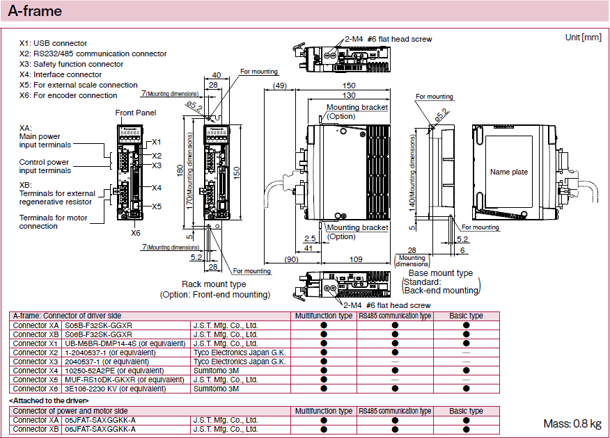
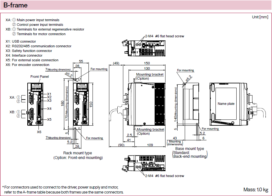
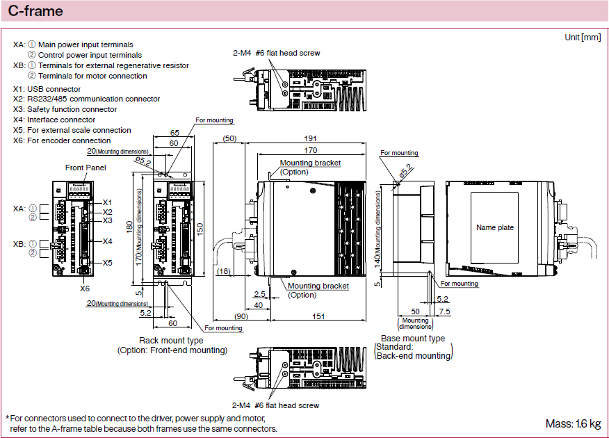
Dimensions
Dimensions of Motor
For motors, please refer to each part number detail.
Motor Search by Specifications
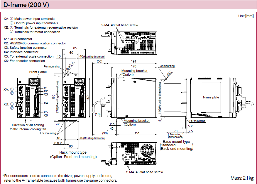
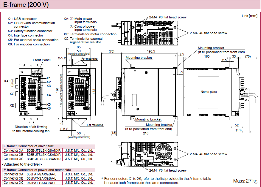
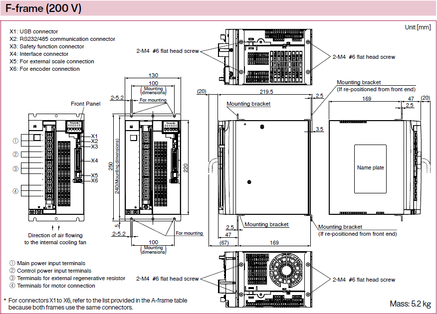
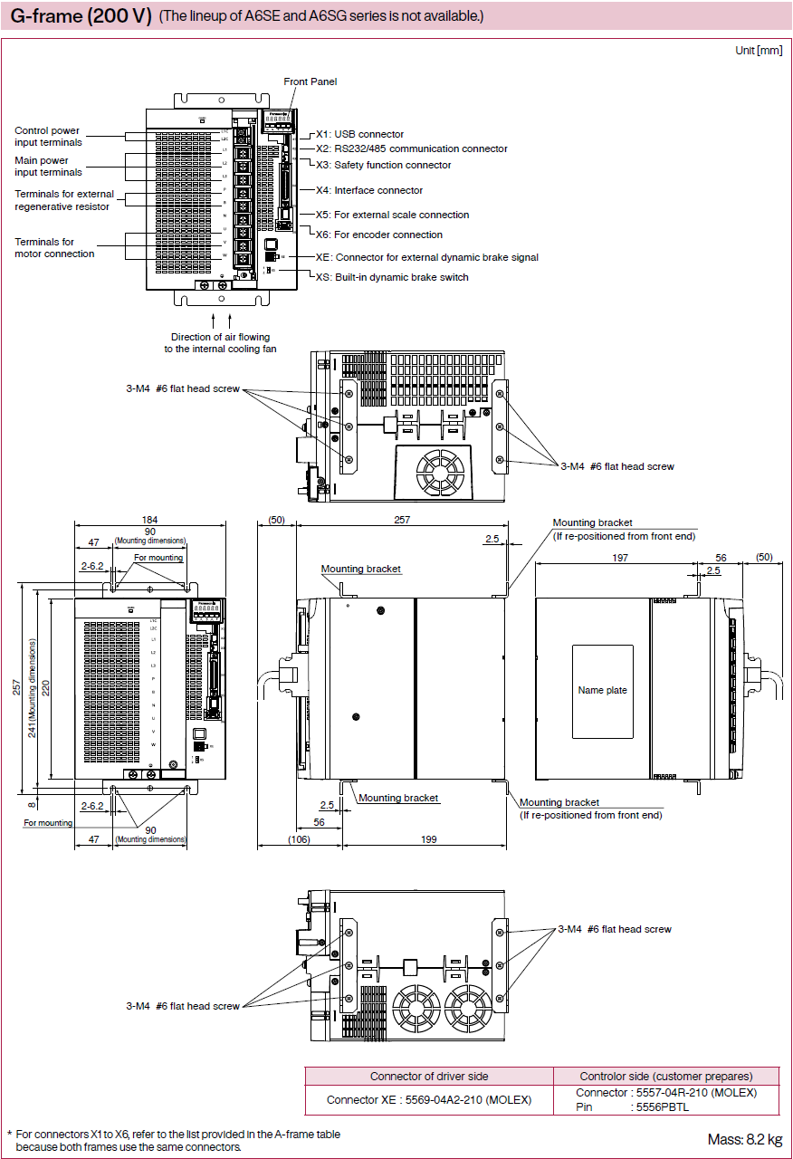
Dimensions of Driver
* All dimensions shown in this catalog are for A6SF series. But external dimensions are also same for A6SE and A6SG series.
For appearance, refer to System Configuration.

- 1.Wiring Diagram (Wiring to Connector, XA, XB, XC and Terminal Block)
- 2.Safety Function (Wiring to the Connector, X3)
- 3.Control Circuit Diagram (Wiring to the Connector, X4 ,X5 ,X6)
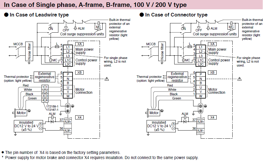
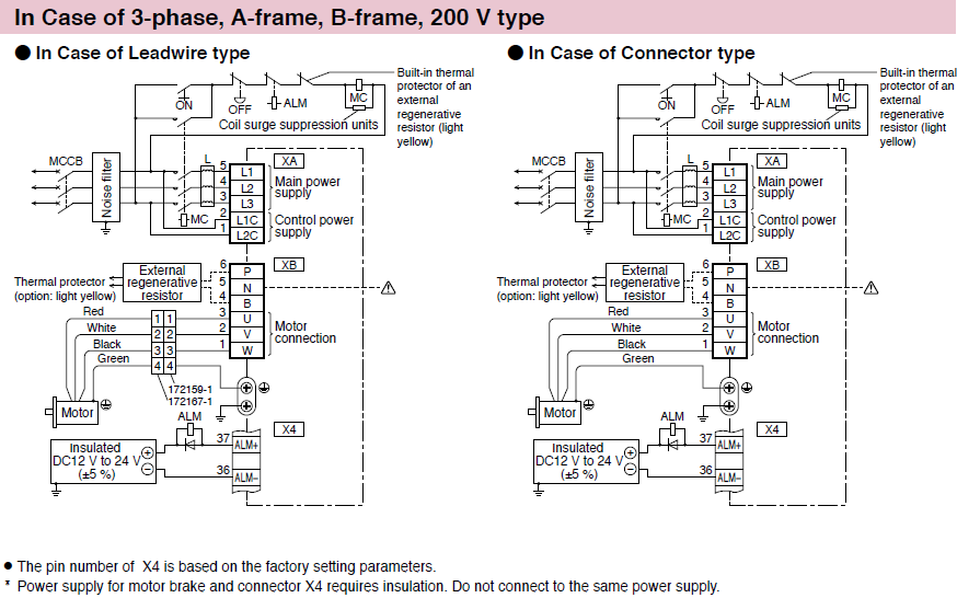
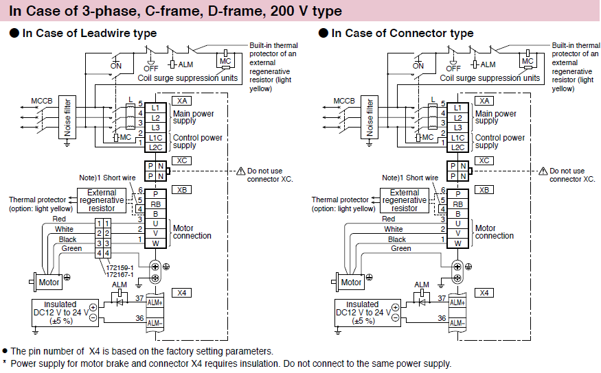
Wiring Diagram
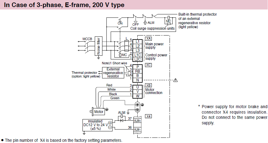
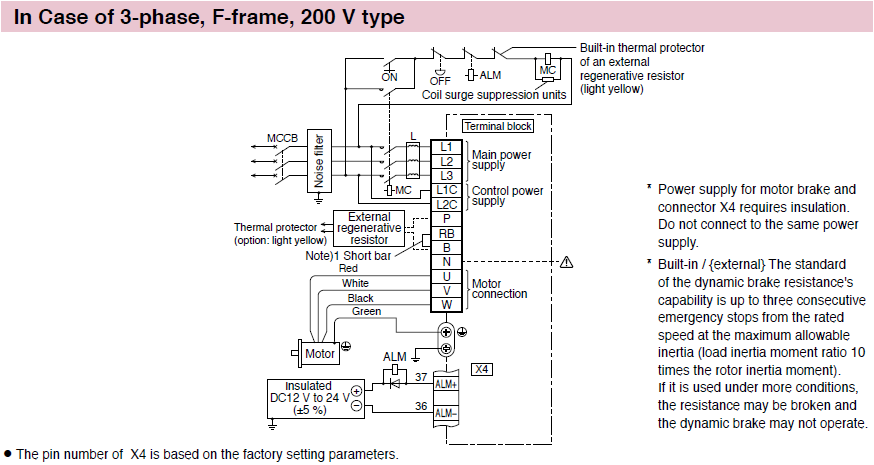
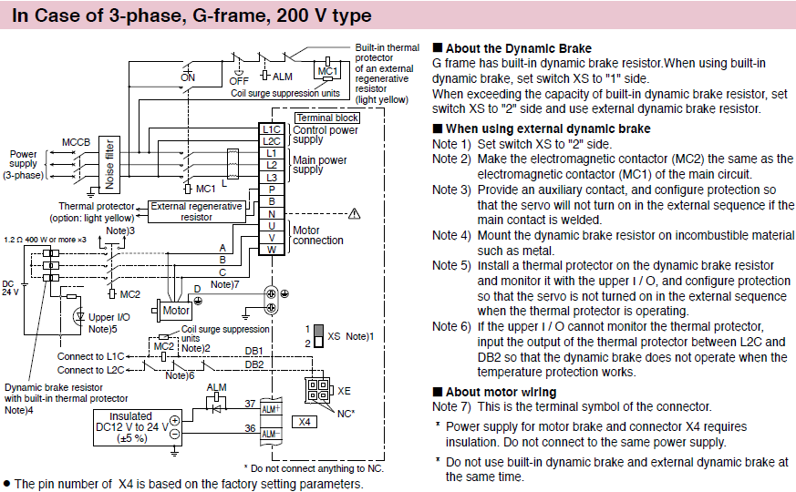
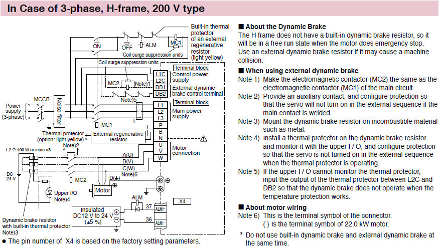
Wiring to Connector, XA, XB, XC and Terminal Block
Connect an external regenerative resistor.
| Frame No. | Short wire (Accessory) | Built-in regenerative resistor | Connection of the connector XB | |
|---|---|---|---|---|
| In case of using an external regenerative resistor | In case of not using an external regenerative resistor | |||
| A-frame B-frame | without | without | • Connect an external regenerative resistor between P-B. | • Always open between P-B. |

Note)1
| Frame No. | Short wire (Accessory) | Built-in regenerative resistor | Connection of the connector XB | |
|---|---|---|---|---|
| In case of using an external regenerative resistor | In case of not using an external regenerative resistor | |||
| C-frame D-frame | with | with | • Remove the short wire accessory from between RB-B. • Connect an external regenerative resistor between P-B. | • Shorted between RB-B with an attached short wire |
Note)1
| Frame No. | Short wire (Accessory) | Built-in regenerative resistor | Connection of the connector XC | |
|---|---|---|---|---|
| In case of using an external regenerative resistor | In case of not using an external regenerative resistor | |||
| E-frame | with | with | • Remove the short wire accessory from between RB-B. • Connect an external regenerative resistor between P-B. | • Shorted between RB-B with an attached short wire |
Note)1
| Frame No. | Short bar (Accessory) | Built-in regenerative resistor | Connection of terminal block | |
|---|---|---|---|---|
| In case of using an external regenerative resistor | In case of not using an external regenerative resistor | |||
| F-frame | with | with | • Remove the short bar accessory from between RB-B. • Connect an external regenerative resistor between P-B. | • Shorted between RB-B with an attached short bar |
Connection of regenerative resistor
| Frame No. | Short bar (Accessory) | Built-in regenerative resistor | Connection of terminal block | |
|---|---|---|---|---|
| In case of using an external regenerative resistor | In case of not using an external regenerative resistor | |||
| G-frame | without | without | • Connect an external regenerative resistor between P-B. | • Always open between P-B. |
Connection of regenerative resistor
| Frame No. | Short bar (Accessory) | Built-in regenerative resistor | Connection of terminal block | |
|---|---|---|---|---|
| In case of using an external regenerative resistor | In case of not using an external regenerative resistor | |||
| H-frame | without | without | • Connect an external regenerative resistor between P-B. | • Always open between P-B. |
Safety Function
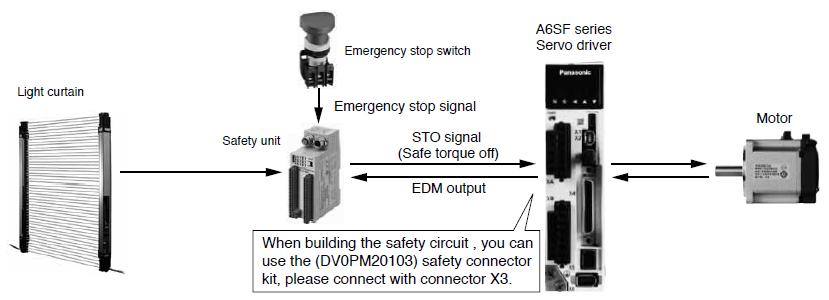
Wiring to the Connector, X3 * Excluding A6 SE, A6 SG Series
Connecting the host controller can configure a safety circuit that controls the safety functions.
When not constructing the safety circuit, use the supplied safety bypass plug.
Outline Description of Safe Torque Off (STO)
The safe torque off (STO) function is a safety function that shuts the motor current and turns off motor output torque by forcibly turning off the driving signal of the servo driver internal power transistor. For this purpose, the STO uses safety input signal and hardware (circuit).
When STO function operates, the servo driver turns off the servo ready output signal (S-RDY) and enters STO state. When the driver becomes STO state, front panel displays the “St.”. Then, when the driver's state is STO input is off and servo-on input is off, the driver automatically becomes servo-off.
Safety Precautions
●When using the STO function, be sure to perform equipment risk assessment to ensure that the system conforms to the safety requirements.
●Even while the STO function is working, the following potential safety hazards exist. Check safety in risk assessment.
- The motor may move when external force (e.g. gravity force on vertical axis) is exerted on it. Provide an external brake, etc., as necessary to secure the motor. Note that the purpose of motor with brake is holding and it cannot be used for braking application.
- When parameter Pr5.10 Sequence at alarm is set to free run (disable dynamic brake), the motor is free run state and requires longer stop distance even if no external force is applied. Make sure that this does not cause any problem.
- When power transistor, etc., becomes defective, the motor will move to the extent equivalent of 180 electrical angle (max.). Make sure that this does not cause any problem.
- The STO turns off the current to the motor but does not turn off power to the servo driver and does not isolate it. When starting maintenance service on the servo driver, turn off the driver by using a different disconnecting device.
●External device monitor (EDM) output signal is not a safety signal. Do not use it for an application other than failure monitoring.
●Dynamic brake and external brake release signal output are not related to safety function. When designing the system, make sure that the failure of external brake release during STO condition does not result in danger condition.
●When using STO function, connect equipment conforming to the safety standards.
[Connector pin assignment](Viewed from cable)
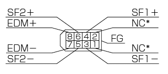
* Do not connect anything to NC.
●System configuration
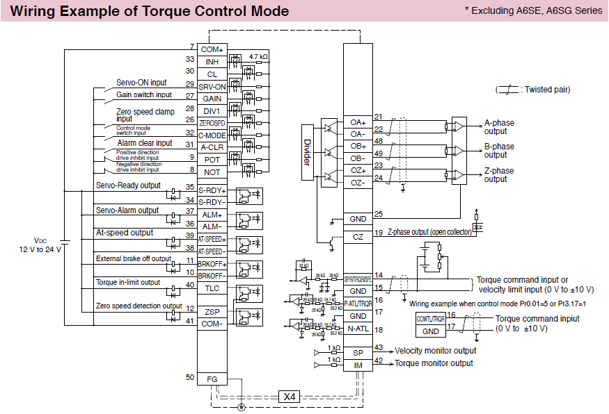
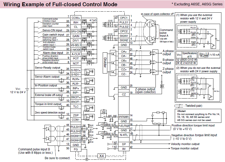
Control Circuit Diagram
Wiring to the Connector, X4
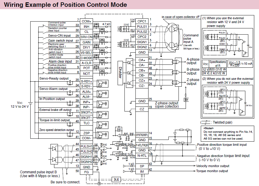
The functions of the following pin can be changed using parameters.
Input: 8, 9, 26, 27, 28, 29, 31, 32
Output: 10-11, 12, 34-35, 36-37, 38-39, 40
* The above diagram is a composition of the shipment parameter.
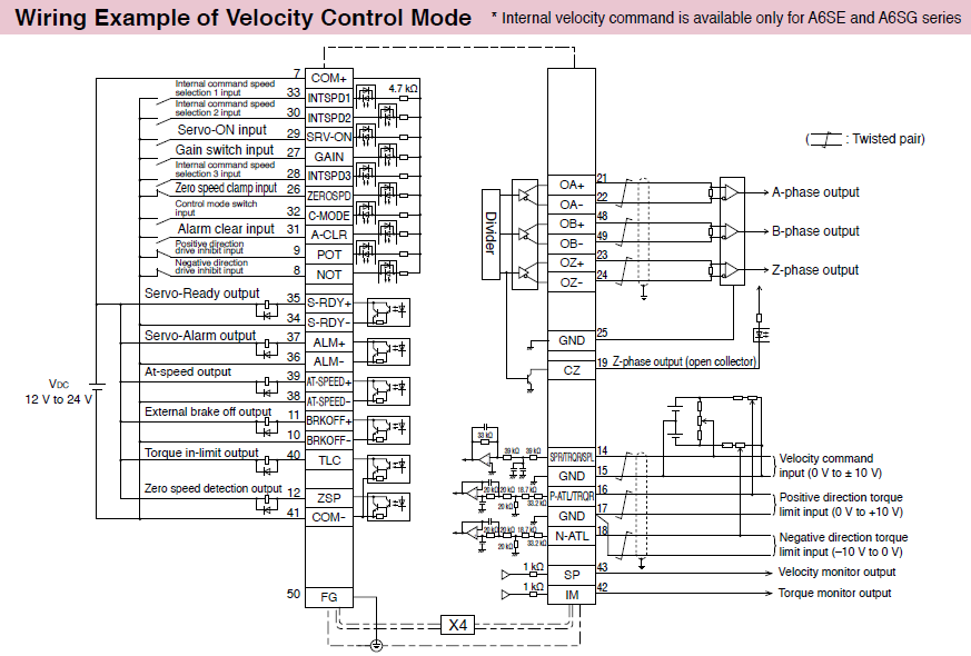
The functions of the following pin can be changed using parameters.
Input: 8, 9, 26, 27, 28, 29, 31, 32, 33
Output: 10-11, 12, 34-35, 36-37, 38-39, 40
* The above diagram is a composition of the shipment parameter.
The functions of the following pin can be changed using parameters
.Input: 8, 9, 26, 27, 28, 29, 31, 32, 33
Output: 10-11, 12, 34-35, 36-37, 38-39, 40
* The above diagram is a composition of the shipment parameter.
The functions of the following pin can be changed using parameters.
Input: 8, 9, 26, 27, 28, 29, 31, 32
Output: 10-11, 12, 34-35, 36-37, 38-39, 40
* The above diagram is a composition of the shipment parameter.
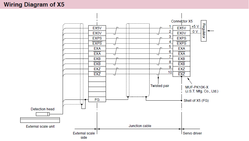
Wiring to the Connector, X5 * Excluding A6 SE, A6 SG Series
Applicable External Scale
| Scale Type | Partner | Series | Resolution*1 [μm] | Max. rate*1 [m/s] |
|---|---|---|---|---|
Parallel Type (A/B/Z phase) | General | — | Maximum speed after4× multiplication : 4 Mpps | |
Serial communication (Incremental) | Magnescale Co., Ltd. | SL700-PL101RP/RHP SL710-PL101RP/RHP | 0.1 | 10 |
BL50H | 0.001 | 3 | ||
| NIDEC INSTRUMENTS CORPORATION | PSLH041+PSLG | 0.1 | 6 | |
| NIDEC MACHINE TOOL CORPORATION | MPLIN | 0.1 | 30 | |
Serial communication (Absolute) | FAGOR AUTOMATION | G3BP/S3BP/SV3BP | 0.001/0.01 | 3 |
L3BP | 0.01/0.05 | 3 | ||
EXA/ EXG/ EXT | 0.01/0.05 | 8 | ||
H2AP-D200 *2/ H2AP-D90 *2 | 29 bit/ 23 bit | 750 r/min / 1500 r/min | ||
H3BP-D90 *2 | 28 bit | 3000 r/min | ||
S2AP-D90 *2 | 28 bit | 1500 r/min | ||
UTP *2 | 23 bit / 27 bit / 28 bit | 6000 r/min / 4000 r/min / 3000 r/min / 2000 r/min | ||
| HEIDENHAIN | LIC 2197P/LIC 2199P | 0.05/0.1 | 10 | |
LIC 4193P/LIC 4195P LIC 4197P/LIC 4199P | 0.001/0.005/0.01 | 10 | ||
LC 195P/LC 495P | 0.001/0.01 | 3 | ||
ECA 4490P *2 | 27 bits to 29 bits | 7000 r/min to 550 r/min | ||
RCN2x9xP/RCN5x9xP *2 | 26 bits/28 bits | 1500 r/min | ||
RCN 8x90P *2 | 29 bit | 500 r/min | ||
| Magnescale Co.,Ltd. | SR27A | 0.01 to 1 | 3.3 | |
| Mitutoyo Corporation | AT573-SC/H | 0.05 | 2.5 | |
ST700 | 0.1 | 5 | ||
ST1300 | 0.001/0.01 | 8 | ||
| NIDEC MACHINE TOOL CORPORATION | MPZA/MPRZ *2 | 23 bits | 10000 r/min, 5000 r/min | |
| Renishaw plc | RESOLUTE | 0.001 | 4 | |
0.05 | 100 | |||
0.1 | 100 | |||
| RSF Electronik | MC 15P MP/MC 15P MK | 0.05/0.1 | 10 | |
MCR 15P *2 | 22 bits to 25 bits | — | ||
*1 There is the difference of resolution and maximum rate from the specification by original supplier as per the servo driver limitation of maximum pulse frequency. The maximum pulse frequency is 4 Gppsfor A6 series. We show the value of A6 family on this table.
*2 Only a limited series of drivers support rotary scales.
| Motor type | Feedback Scale Specifications | Supported driver series |
|---|---|---|
| Rotary motor | Incremental Rotary Scale | A6SF, A6NF, A6BF |
| Absolute Rotary Scale | A6BF | |
| Linear motor / Direct Drive motor | Incremental Rotary Scale | A6SM, A6SL, A6NM, A6NL, A6BM, A6BL |
| Absolute Rotary Scale | A6SM, A6SL, A6NM, A6NL, A6BM, A6BL |
* Please contact us when you study the system with a scale because the driver and the scale combination has restriction as per the feedback system between full closed control system and linear system.
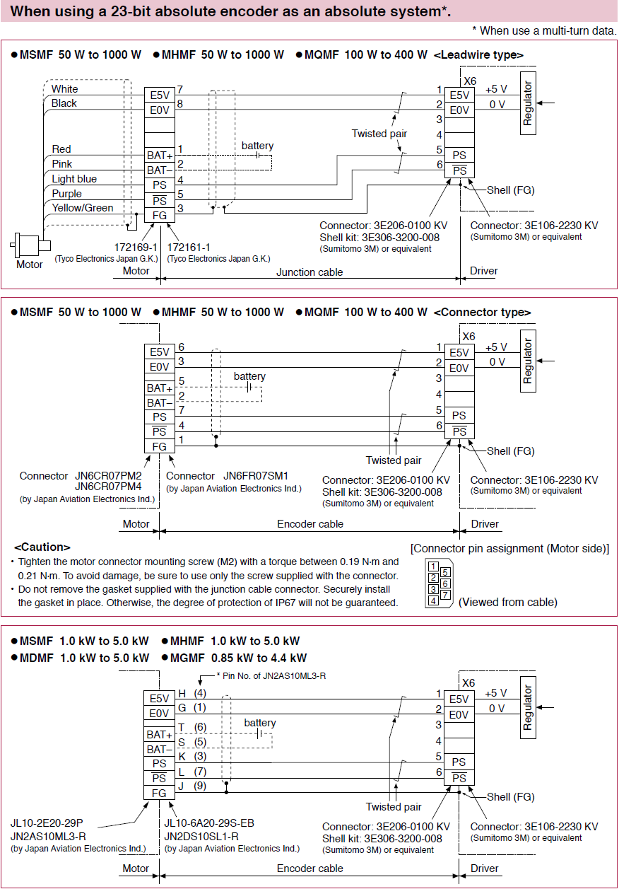
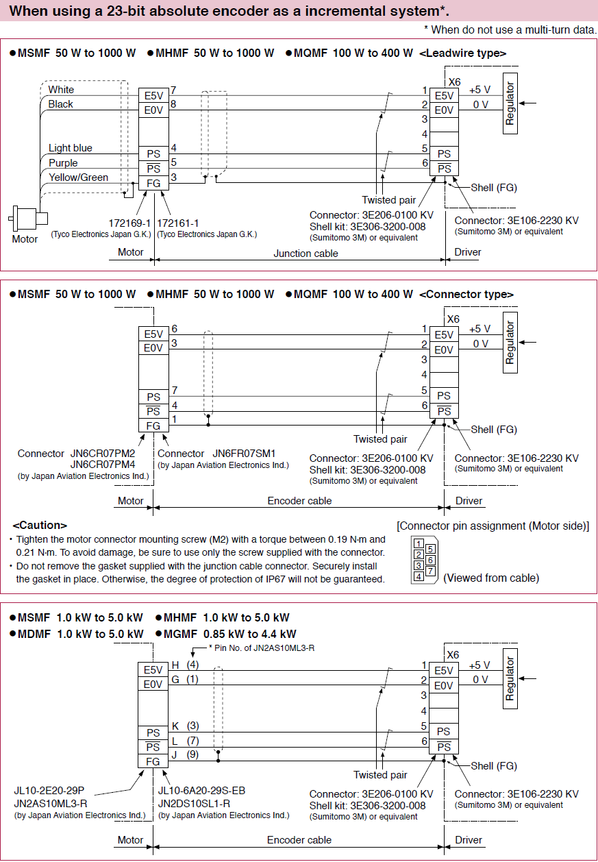
Wiring to the Connector, X6