Basic Information

High-Speed, Airless Charge Removal


UL, CSA : Certified by TÜV SÜD America Inc.
Features
"Fast Charge Removal", "Airless", "Low-Pressure". Three charge removal modes for diverse application coverage
The ER-X series offers an airless charge removal capability to eliminate the need for compressed air in addition to low pressure and high speed compressed air based modes. Furthermore, it supports dual-head configurations for expanded application coverage.

Massive ion discharge when using air reduces charge removal time
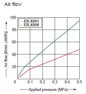
By applying a compressed air source, the ion volume increases providing an improved tact time for substrate ionization. This makes the ER-X suitable for applications such as electronic paper and thin film solar cells, where charge removal time is directly linked to productivity.
Prevents dust dispersion and cleanliness degradation!
The ER-X series can effectively remove surface charges with an air pressure of less than 0.05 MPa. With the advantage of minimal dust dispersion, it is suitable for charge removal in semiconductor, FPD (mobile panel), and other applications that require high degree of cleanliness. The presence of air also helps prevent adhesion of dust to the discharge needles, requiring less cleaning than in the airless charge removal mode.


0.3 sec. or less*1 fastest charge removal achieved with pulse AC method spot type ionizer*2

The pulse AC method enables the ER-X001 to generate and discharge a large amount of ions, which makes charge removal faster. Furthermore, as a spot type ionizer, it achieves the fastest charge removal of 0.3 sec.or less*2
*1: Spot diameter of ø15 mm ø0.591 in or less
*2: Based on research conducted by our company as of December 2025.

![]()


Charge removal and dust removal while separating TAB protective film

Charge removal of molded plastic components on a conveyor belt

Charge removal and dust removal of digital camera cases on a conveyor belt

Removing dust during instrument panel assembly

Removing dust during food product cup transport

Preventing adhesion of molded parts to molds

Prevention of part feeder clogging

High-speed charge removal on FPCs

Preventing electrostatic damage during bonding

High-speed charge removal on taping machine

Airless charge removal of minute components on a conveyor belt

Order guide
Heads
Head connection cable is not supplied with the head. Please order it separately.
| Type | Appearance | Charge removal time | Ion balance | Effective charge removal width | Model No. | |
|---|---|---|---|---|---|---|
| Spot type |
| 0.3 sec. or less (Note 1), 0.5 sec. or less (Note 2) | ±30 V or less (Note 2, 3) | 50 mm 1.969 in approx. | ER-X001 (Note 4) | |
| Bar type |
| 1 sec. or less (Note 2) | 80 mm 3.150 in approx. | ER-X008 (Note 4) | ||
| High and low temperature resistant | ER-X008HC (Note 5) | |||||
| 160 mm 6.299 in approx. | ER-X016 | ||||
| High and low temperature resistant | ER-X016HC (Note 5) | |||||
| 320 mm 12.598 in approx. | ER-X032 | ||||
| High and low temperature resistant | ER-X032HC (Note 5) | |||||
| 480 mm 18.898 in approx. | ER-X048 | ||||
| High and low temperature resistant | ER-X048HC (Note 5) | |||||
| 640mm 25.197 in approx. | ER-X064 | ||||
| High and low temperature resistant | ER-X064HC (Note 5) | |||||


Note 1: Typical value in condition of discharge distance 50 mm 1.969 in, center of the product, discharge frequency 50 Hz and air supply 60 ℓ/min.(0.3 MPa).
Note 2: Typical value in condition of discharge distance 100 mm 3.937 in (ER-X001: 50 mm 1.969 in), center of the product, discharge frequency 50 Hz (ER‑X□HC:30 Hz) and no air supply.
Note 3: Ion balance refers to the average value of plus and minus. The specification value is the typical one in condition used when ambient temperature change is less than ±10 ℃, ion balance is set after 30 minutes from the discharge start, the ion balance control function is set ON.
Note 4: The ER-X001 and ER-X008 must be combined with the new-type ER-XC02 controller (produced from April 2014 on).
Refer to "Identification of previous-type and new-type controllers and for the combination with the head".
Note 5: The ER-X□HC high / low temperature resistant type head can be used under temperatures from -60 to +200 ℃ -76 to +392 ℉. Be sure to use this head in combination with the new-type controller, ER-XC02 (produced from April 2016 on).
Refer to "Identification of previous-type and new-type controllers and for the combination with the head".
Controller
Please order power cable or AC adapter separately.
| Type | Appearance | Model No. | Number of heads connected | Output |
|---|---|---|---|---|
| Standard type |
| ER-XC02 | Max. 2 units | PhotoMOS relay |
Head connection cable
Head connection cable is not supplied with the head. Please order it separately.
| Appearance | Model No. | Description | |
|---|---|---|---|
| ER-XCCJ2H | Length: 2 m 6.562 ft Net weight: 120 g approx. | Cabtyre cable with both connector |
| ER-XCCJ5H | Length: 5 m 16.404 ft Net weight: 290 g approx. | ||
| ER-XCCJ10H (Note) | Length: 10 m 32.808 ft Net weight: 560 g approx. | ||
Note: Cannot be used with the high and low temperature resistant type head ER-X□HC.
Option
| Designation | Model No. | Description | |
|---|---|---|---|
| Power cable | ER-XCC2 | Length: 2 m 6.562 ft, Net weight: 80 g approx. | 0.15 mm2 10-core cabtyre cable with connector Cable outer diameter: ø5.3 mm ø0.209 in |
| ER-XCC5 | Length: 5 m 16.404 ft, Net weight: 190 g approx. | ||
| Discharge needle unit | ER-XANT | For ER-X016/X032/X048/X064. (Note 1) Unit with replacement tungsten needles: 1 pc. | |
| ER-XANT1 | For ER-X001. Unit with replacement tungsten needles: 1 pc. | ||
| ER-XANT2 | For ER-X008. (Note 1) Unit with replacement tungsten needles: 1 pc. | ||
| ER-XANTHC | For ER-X016HC/X032HC/X048HC/X064HC. Unit with replacement tungsten needles: 1 pc. | ||
| ER-XANT2HC | For ER-X008HC. Unit with replacement tungsten needles: 1 pc. | ||
| Discharge part protective cover | ER-XACVR | For ER-X016/X032/X048/X064. (Note 1) Enables to prevent electric shock by mounting to the heads. 2 pcs per set. (Note 2) Material: Polycarbonate Weight: 20 g approx. (1 set) * No effect on charge removal capacity of the heads by mounting a discharge part protection cover. | |
Notes:
1) Cannot be used with the high and low temperature resistanttype head ER-X□HC.
2) The number of set(s) you need depends on the head model No.
| Model No. | ER-X016 | ER-X032 | ER-X048 | ER-X064 |
|---|---|---|---|---|
| No. of set (2 pcs per set) | 1 set | 2 sets | 3 sets | 4 sets |
Power cable
ER-XCC□
Discharge needle unit
ER-XANT
ER-XANTHC

ER-XANT1

ER-XANT2
ER-XANT2HC

Discharge part protective cover
ER-XACVR

Specifications
Heads
| Type | Spot type | Bar type | ||||
|---|---|---|---|---|---|---|
| Model No. | ER-X001 | ER-X008 | ER-X016 | ER-X032 | ER-X048 | ER-X064 |
| Applicable regulations and certifications | CE Marking (EMC Directive, RoHS Directive), UKCA Marking (EMC Regulations, RoHS Regulations), TÜV SÜD certification (USA, Canada) | |||||
| Effective charge removal width | 50 mm 1.969 in approx. | 80 mm 3.150 in approx. | 160 mm 6.299 in approx. | 320 mm 12.598 in approx. | 480 mm 18.898 in approx. | 640 mm 25.197 in approx. |
| Charge removal time | 0.3 sec. or less (Note 1), 0.5 sec. or less (Note 2) | 1 sec. or less (Note 2) | ||||
| Ion balance | ±30 V or less (Note 2, 3) | |||||
| Discharge method | Pulse AC method | |||||
| Discharge frequency | 50 Hz / 20 Hz | 50 Hz / 30 Hz / 20 Hz / 10 Hz / 5 Hz / 1 Hz | 100 Hz / 70 Hz / 50 Hz / 30 Hz / 20 Hz / 10 Hz / 5 Hz / 1 Hz | |||
| Discharge output voltage | ±7,000 V approx. | |||||
| Ozone generation | 0.01 ppm or less (Note 2) | |||||
| Maximum air pressure | 0.5 MPa | |||||
| Applicable fluid | Air (dried clean air) (Note 4) | |||||
| Operating altitude | 2,000 m 6561.68 ft or less (Note 5) | |||||
| Ambient temperature | 0 to +50 ℃ +32 to +122 ℉ (ER-X001: 0 to +40 ℃ +32 to +104 ℉) (No dew condensation), Storage: -10 to +65 ℃ +14 to +149 ℉ | |||||
| Ambient humidity | 35 to 65 % RH, Storage: 35 to 85 % RH | |||||
| Vibration resistance | 10 to 55 Hz (ER-X001: 10 to 150 Hz) frequency, 0.75 mm 0.030 in double amplitude or maximum acceleration 49 m/s2, in X, Y and Z directions for two hours each | |||||
| Shock resistance | 100 m/s2 acceleration (10 G approx.), in X, Y and Z directions three times each | |||||
| Enclosure grounding method | Floating | |||||
| Material | Main unit enclosure: PPS, Stainless steal (SUS), Head mounting bracket: Stainless steal (SUS), Discharge needle: PC, PPS, Tungsten [ER-X001 – Main unit enclosure: Stainless steel (SUS), Head mounting bracket: Stainless steel (SUS), Discharge needle: PFA, Tungsten] | |||||
| Length of high-voltage cable | 1.2 m 3.937 ft | 0.5 m 1.640 ft | 0.5 m 1.640 ft | |||
| Net weight | 370 g approx. | 330 g approx. | 410 g approx. | 530 g approx. | 650 g approx. | 780 g approx. |
| Accessory | Head mounting bracket (mounted at the factory) | |||||
| Type | High and low temperature resistant | ||||
|---|---|---|---|---|---|
| Model No. | ER-X008HC | ER-X016HC | ER-X032HC | ER-X048HC | ER-X064HC |
| Applicable regulations and certifications | CE Marking (EMC Directive, RoHS Directive), UKCA Marking (EMC Regulations, RoHS Regulations), TÜV SÜD certification (USA, Canada) | ||||
| Effective charge removal width | 80 mm 3.150 in approx. | 160 mm 6.299 in approx. | 320 mm 12.598 in approx. | 480 mm 18.898 in approx. | 640 mm 25.197 in approx. |
| Charge removal time | 1 sec. or less (Note 2) | ||||
| Ion balance | ±30 V or less (Note 2, 3) | ||||
| Discharge method | Pulse AC method | ||||
| Discharge frequency | 30 Hz (Note 6) | ||||
| Discharge output voltage | ±7,000 V approx. | ||||
| Ozone generation | 0.01 ppm or less (Note 2) | ||||
| Maximum air pressure | 0.1 MPa | ||||
| Applicable fluid | Air (dried clean air) (Note 4) | ||||
| Operating altitude | 2,000 m 6561.68 ft or less (Note 5) | ||||
| Ambient temperature | Head: -60 to +200 ℃ -76 to +392 ℉ (No dew condensation or icing) (Note 7), Storage: -10 to +65 ℃ +14 to +149 ℉ High voltage unit: 0 to +50 ℃ +32 to +122 ℉ (No dew condensation), Storage: -10 to +65 ℃ +14 to +149 ℉ | ||||
| Ambient humidity | 35 to 65 % RH, Storage: 35 to 85 % RH | ||||
| Vibration resistance | 10 to 55 Hz frequency, 0.75 mm 0.030 in (Max. acceleration 50 m/s2) double amplitude in X, Y and Z directions for two hours each | ||||
| Shock resistance | 100 m/s2 acceleration (10 G approx.), in X, Y and Z directions three times each | ||||
| Enclosure grounding method | Floating | ||||
| Material | Main unit enclosure: PPS, Stainless steal (SUS), Head mounting bracket: Stainless steal (SUS), Discharge needle: PPS, Tungsten, Main unit enclosure of high-voltage unit: ABS | ||||
| Length of high-voltage cable | Heat-resistant shielded cable, 1.8 m 5.906 ft | ||||
| Net weight | 420 g approx. | 490 g approx. | 620 g approx. | 760 g approx. | 900 g approx. |
| Accessories | ø6 ø0.236-4 Air tube joint: 1 pc., Seal cap: 1 pc., Head mounting bracket (mounted at the factory) | ||||
Notes:
1) Typical value in condition of discharge distance 50 mm 1.969 in, center of the product, discharge frequency 50 Hz and air supply 60 ℓ/min.(0.3 MPa).
2) Typical value in condition of discharge distance 100 mm 3.937 in (ER-X001: 50 mm 1.969 in), center of the product, discharge frequency 50 Hz (ER‑X□HC:30 Hz) and no air supply.
3) Ion balance refers to the average value of plus and minus. The specification value is the typical one in condition used when ambient temperature change is less than ±10 ℃, ion balance is set after 30 minutes from the discharge start, the ion balance control function is set ON.
4) The dried clean air is the air dried (dew point: equivalent of -20 ℃ -4 ℉) and filtered (mesh-size: equivalent of 0.01 μm).
5) Do not use or store in an environment that has been pressurized to an air pressure higher than the atmospheric pressure at 0 m.
6) Set the discharge frequency to 30 Hz. Do not use any other frequency.
7) Discoloration of the head may occur when used under high temperatures, but it does not affect the charge removal performance.
Allowable ambient temperature of high and low temperature resistant type head ER-X□HC and its installation
When installing, make sure to expose a section measuring 500 mm 19.685 in or more to the normal temperature area as shown below for the protection of the high-voltage unit.

Note: The high and low temperature resistant type ER-X□HC cannot be connected with the ER-XCCJ10H head connection cable (10 m32.808 ftin length).
Controller
| Type | Controller | |
|---|---|---|
| Model No. | ER-XC02 | |
| Applicable regulations and certifications | CE Marking (EMC Directive, RoHS Directive), UKCA Marking (EMC Regulations, RoHS Regulations), TÜV SÜD certification (USA, Canada) | |
| Number of heads connected | Maximum 2 units | |
| Supply voltage | 24 V DC ±10 % | |
| Current consumption | 450 mA or less when connecting 1 heads, 800 mA or less when connecting 2 heads | |
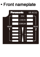
| Indictor | Displays status of Head 1 and 2 | |
| DSC (Discharge) | Green LED (lights up when discharging) | |
| CHECK | Orange LED (lights up when dirt, wear, etc. of the discharge needle is detected) | |
| ERROR | Red LED (lights up when abnormal discharge is detected) | |
| Level meter | Green LED (5 levels, lights up depending on amount of the charge or ion generation) | |
| Output [ALARM ERROR COM (Common)] | PhotoMOS relay output • Maximum load current: 100 mA • Applied voltage: 30 V DC or less (between output-output common) • Residual voltage: 1.5 V or less (at load current of 100 mA) | |
| Output operation | ALARM: ON when dirt or wear of the discharge needle is detected; OFF when operation is normal. ERROR: OFF when abnormal discharge is detected; ON when operation is normal. | |
| Short-circuit protection | Incorporated (automatic reset type) | |
| Discharge control input (DSC OFF) | Discharge allowed: Open, Discharge halt: 24 V or 0 V shorted | |
| Contamination level | 2 | |
| Overvoltage category | I | |
| Elevation | 2,000 m 6561.68 ft or less (Note) | |
| Ambient temperature | 0 to +50 ℃ +32 to +122 ℉ (No dew condensation), Storage: -10 to +65 ℃ +14 to +149 ℉ | |
| Ambient humidity | 35 to 65 % RH, Storage: 35 to 85 % RH | |
| Voltage withstandability | 1,000 V AC for one min. between all supply terminals connected together and enclosure 500 V AC for on min. between supply terminals and F.G. | |
| Insulation resistance | 20 MΩ, or more, with 250 V DC megger between all supply terminals connected together and enclosure | |
| Vibration resistance | 10 to 150 Hz frequency, 0.75 mm 0.030 in double amplitude or maximum acceleration 49 m/s2, in X, Y and Z directions for two hours each | |
| Shock resistance | 100 m/s2 acceleration (10 G approx.) in X, Y and Z directions three times each | |
| Enclosure grounding method | Floating | |
| Material | Enclosure: ABS | |
| Net Weight | 130 g approx. | |
| Accessories | Power supply / I/O connector: 1 set (Housing 5557-10R, Terminal 5556TL [manufactured by Molex]) Ground wire (3.7 m 12.139 ft approx.): 1 pc. | |
Note: Do not use or store in an environment that has been pressurized to an air pressure higher than the atmospheric pressure at 0 m.
Dimensions
- Unit: mm in
ER-X008 / ER-X016 / ER-X032 / ER-X048 / ER-X064
Head
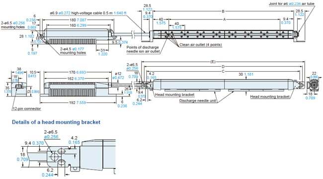
| Model No. | A | B | C | D | (E) |
|---|---|---|---|---|---|
| ER-X008 | 40 1.575 | 106 4.173 | 138 5.433 | 150 5.906 | 163 6.417 |
| ER-X016 | 120 4.724 | 194 7.638 | 226 8.898 | 238 9.370 | 251 9.882 |
| ER-X032 | 280 11.024 | 354 13.937 | 386 15.197 | 398 15.669 | 411 16.181 |
| ER-X048 | 440 17.323 | 514 20.236 | 546 21.496 | 558 21.969 | 571 22.480 |
| ER-X064 | 600 23.622 | 674 26.535 | 706 27.795 | 718 28.268 | 731 28.780 |
Mounting drawing with discharge part protective cover (ER-XACVR)
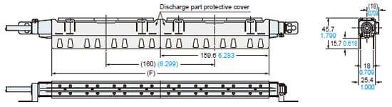
Note: The ER-XACVR discharge part protective cover cannot be used on the ER-X008 or high and low temperature resistant type head ER-X□HC.
| Model No. | (F) |
|---|---|
| ER-X016 | 159.6 6.283 |
| ER-X032 | 319.6 12.583 |
| ER-X048 | 479.6 18.882 |
| ER-X064 | 639.6 25.181 |
ER-X008HC / ER-X016HC / ER-X032HC / ER-X048HC / ER-X064HC
Head
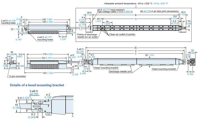
| Model No. | A | B | C | D | (E) |
|---|---|---|---|---|---|
| ER-X008HC | 40 1.575 | 106 4.173 | 138 5.433 | 150 5.906 | 163 6.417 |
| ER-X016HC | 120 4.724 | 194 7.638 | 226 8.898 | 238 9.370 | 251 9.882 |
| ER-X032HC | 280 11.024 | 354 13.937 | 386 15.197 | 398 15.669 | 411 16.181 |
| ER-X048HC | 440 17.323 | 514 20.236 | 546 21.496 | 558 21.969 | 571 22.480 |
| ER-X064HC | 600 23.622 | 674 26.535 | 706 27.795 | 718 28.268 | 731 28.780 |
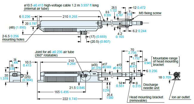
ER-X001
Head
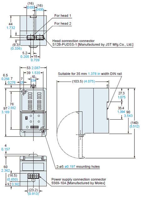
ER-XC02
Controller
ER-XCCJ□H
Head connection cable
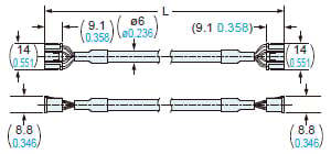
・Length L
| Model No. | Length L |
|---|---|
| ER-XCCJ2H | 2,000 78.740 |
| ER-XCCJ5H | 5,000 196.850 |
| ER-XCCJ10H | 10,000 393.701 |
ER-XCC□
Power cable (Optional)
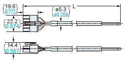
・Length L
| Model No. | Length L |
|---|---|
| ER-XCC2 | 2,000 78.740 |
| ER-XCC5 | 5,000 196.850 |
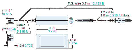
ER-XAPS(-EX) [Discontinued products]
AC adapter (Optional)

Note 1: The AC cable is not enclosed with ER-XAPS-EX.Note 2: The shape of setting switch will be changed from production at May, 2021. Please see drawing below.
Before the modification (produced before April, 2021)
Note: The AC cable is not enclosed with ER-XAPS-EX.
I/O Circuit and Wiring diagrams
New-type controller (produced from April 2014 on)
Notice: Products manufactured from April 2014 and before April 2016 cannot be used with the high and low temperature resistant type head ER-X008HC.
For the Identification of previous-type and new-type controllers and for the combination with the head, refer to
Identification of previous-type and new-type controllers and combination with the head
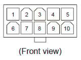
Power connector pin arrangement
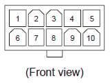
Housing: 5569-10A
[Manufactured by Molex]
| Terminal No. | Terminal name | Color code |
|---|---|---|
| 1 | 0 V | Blue |
| 2 | COM(-) | - |
| 3 | Discharge control input | Pink |
| 4 | COM(OUT) | Violet |
| 5 | F.G. terminal | Green / Yellow |
| 6 | 24 V | Brown |
| 7 | COM(+) | - |
| 8 | COM(IN) | White |
| 9 | Alarm output | Orange |
| 10 | Error output | Black |
Note: Color code refers to cable colors of an optional power supply cable.
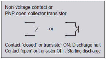
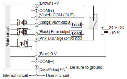
When connecting the output to negative common
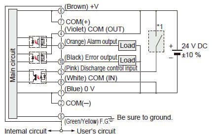
*1
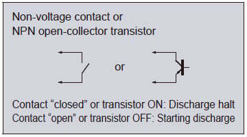
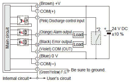
When connecting the output to positive common
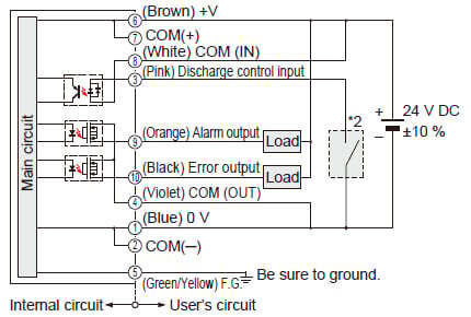
*2
Notes:
1) Be sure to ground the F.G. terminal. If F.G. terminal is not connected properly, it may cause electric shock.
In the case of ER-X001, the head mounting bracket and F.G. terminal are internally connected.
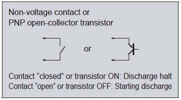
2) To stop discharge, turn ON the discharge control input for 20 ms or longer. To start discharge, turn OFF (open) the discharge control input. Discharge will start in 20 ms.
Previous-type controller (produced before March 2014)
Notice: Products manufactured before March 2014 cannot be used with ER-X001, ER-X008 and the high and low temperature resistant type head ER-X□HC.
For the Identification of previous-type and new-type controllers and for the combination with the head, refer to
Identification of previous-type and new-type controllers and combination with the head
Power connector pin arrangement
Housing: 5569-10A
[Manufactured by Molex]
| Terminal No. | Terminal name | Color code |
|---|---|---|
| 1 | 0 V | Blue |
| 2 | COM(-) | - |
| 3 | Discharge control input | Pink |
| 4 | COM(OUT) | Violet |
| 5 | F.G. terminal | Green / Yellow |
| 6 | 24 V | Brown |
| 7 | COM(+) | - |
| 8 | - | White |
| 9 | Alarm output | Orange |
| 10 | Error output | Black |
Note:
Color code refers to cable colors of an optional power supply cable.
When connecting the output to negative common
*1
When connecting the output to positive common
*2

Notes:
1) Be sure to ground the F.G. terminal. If F.G. terminal is not connected properly, it may cause electric shock.
2) To stop discharge, turn ON the discharge control input for 20 ms or longer. To start discharge, turn OFF (open) the discharge control input. Discharge will start in 20 ms.
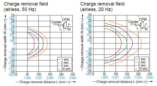
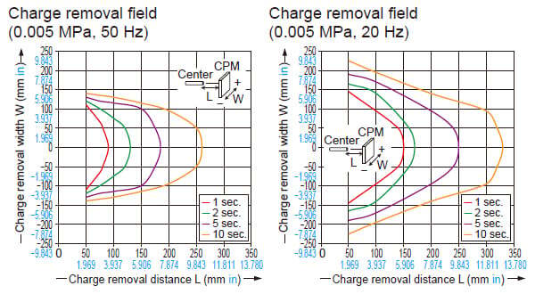
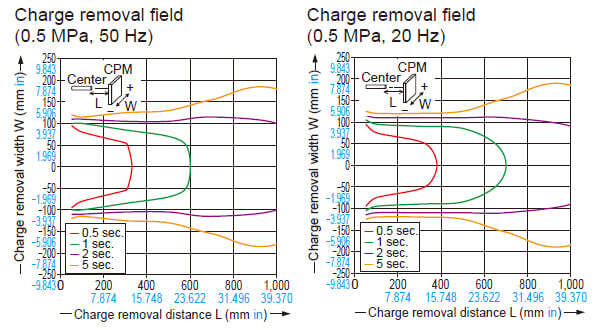
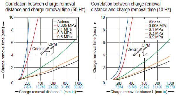
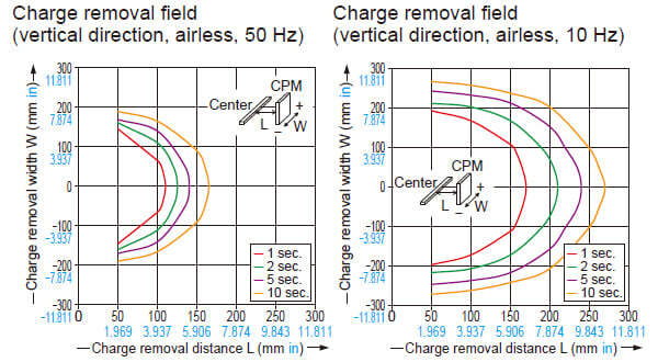
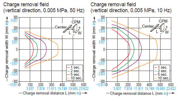
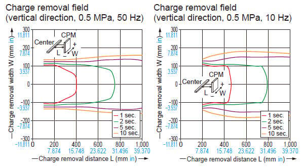
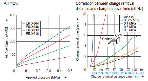
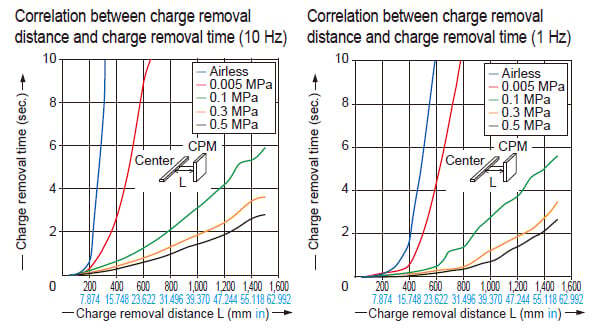
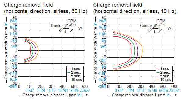
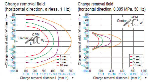
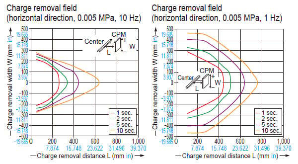
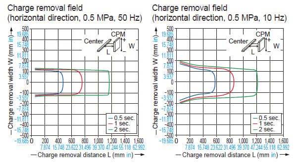
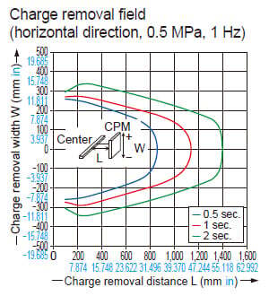
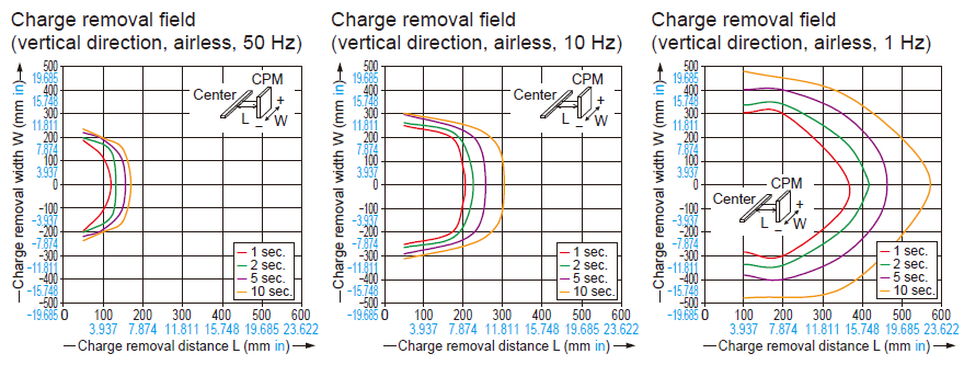
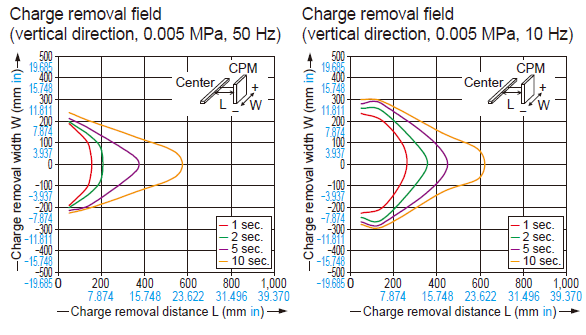
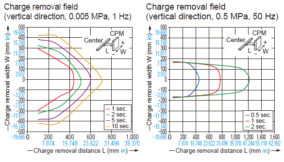
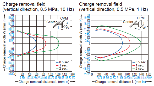
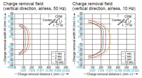
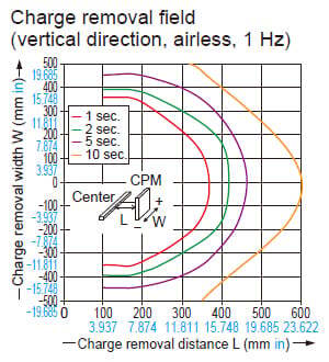
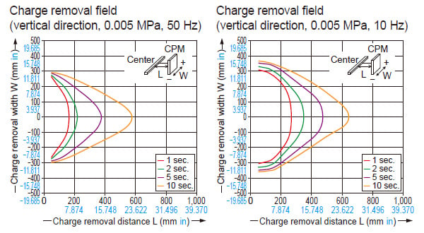
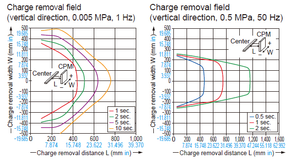
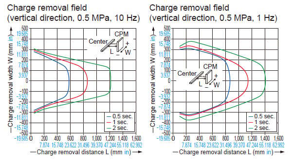
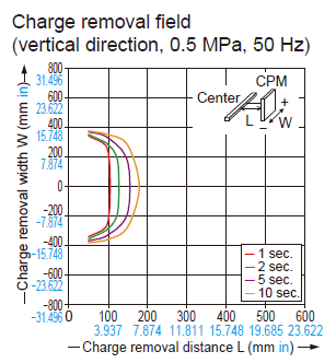
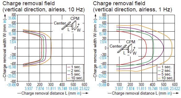
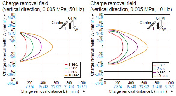
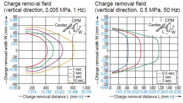
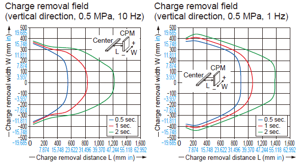
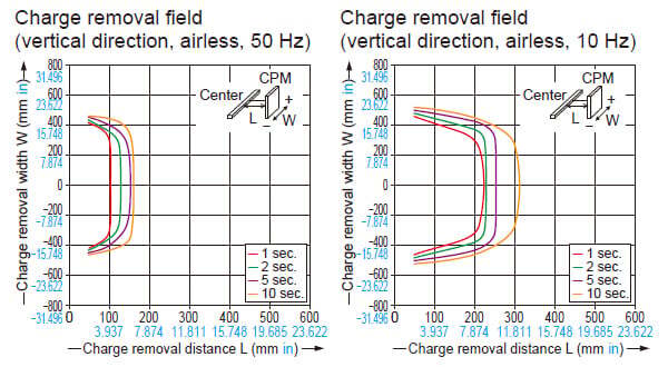
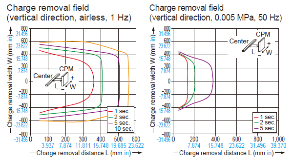
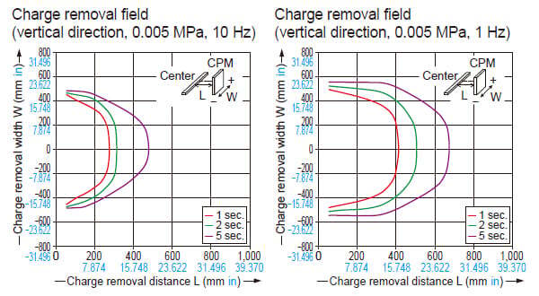
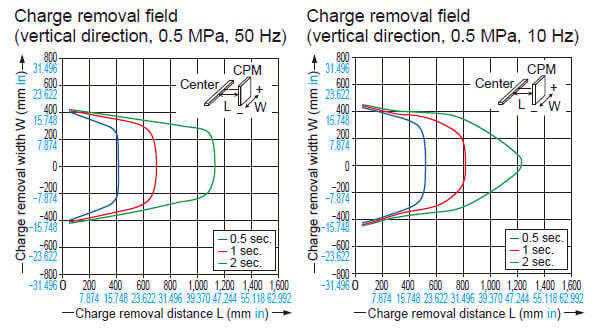
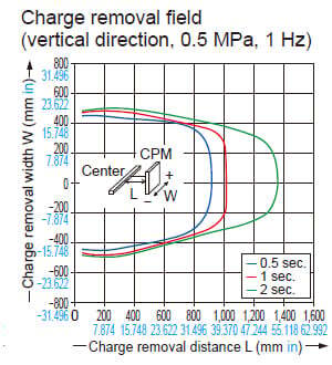
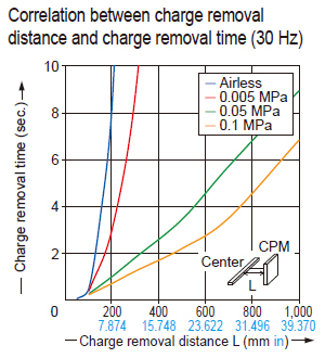
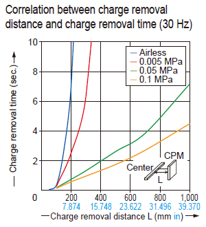
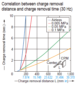
Charge removal characteristics
Measured using a 150 × 150 mm 5.906 × 5.906 in CPM (charge plate monitor). (At center of CPM)
*TYPICAL
Common to ER-X001/X008
ER-X001

ER-X008
Common to ER-X016/X032/X048/X064
ER-X016
ER-X032
ER-X048
ER-X064
Common to ER-X□HC
ER-X008HC
ER-X016HC
ER-X064HC
- When using as a CSA and UL compliant product, use a CLASS 2 CSA/UL certified power supply, or a CSA/UL certified power supply that has been evaluated as a Limited Power Source as specified in CAN/CSA-C22.2 No.60950-1/UL60950-1.
- This product has been developed / produced for industrial use only.
- This product is suitable for indoor use only.
- Do not use this product for purposes other than electric charge removal.
- Do not use this product in environments which are outside the specification range, otherwise operating problems or damage may occur. In addition, the operating life of the product may become significantly reduced.
- This product is a precision device. Do not apply a shock to it by dropping, for example. Accidents or operating problems may occur.
- Never disassemble, repair or modify this product. Accidents or operating problems may occur.
- Do not throw this product in fire. It may explode or toxic fumes may be generated.
- Do not run the wires together with high-voltage lines or power lines or put them in the same raceway. This can cause malfunction due to induction.
- Verify that the supply voltage variation is within the rating.
- In case using switching regulator, be sure to connect F.G. terminal.
- When connecting / removing the head or performing wiring or inspection work, be sure to turn off the power first. Not doing so may result in accidents, electric shock or operating problems.
- After connecting the cables, check that the connections are correct before turning on the power. If the cables are connected incorrectly, operating problems or accidents may occur.
- Do not use a cable with any damage such as cracks or splitting. Risk of accidents and failure.
- Avoid use in a location with significant steam or dust, or in a location where the product may come in direct contact with water, oil, or welding spatter.
- Do not touch the discharge needle with hard objects such as tools. If the discharge needle becomes broken, it will not provide sufficient charge removal performance, and moreover operating problems or accidents may occur.
- During installation, fasten the product securely. If it is not securely fastened or it is subjected to continuous vibration or shock, accidents or operating problems may result.
- Power cable that are 0.15mm2 or more and 30 m 98.425 ft or less in total length for wiring. Also, keep the wiring as short as possible in order to prevent noise.
- When disposing of this product, treat it appropriately as industrial waste.
- After starting discharge, it takes 30 minutes approx. for charge removal performance to stabilize. Therefore, wait 30 minutes before adjusting ion balance.
- Use the correct combination of head, discharge needle unit and controller.
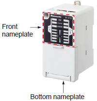
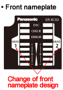
Identification of previous-type and new-type controllers and combination with the head
| Combination | New-type controller (Note) | Previous-type controller (Note) | ||||
|---|---|---|---|---|---|---|
| Produced from April 2016 on | Produced from April 2014 and before April 2016 | Produced before April 2014 | ||||
|
| |||||
|
|
| ||||
| Head | Spot type | ER-X001 | OK | OK | Cannot be used | |
| Bar type | ER-X008 | OK | OK | Cannot be used | ||
| ER-X016 | OK | |||||
| ER-X032 | ||||||
| ER-X048 | ||||||
| ER-X064 | ||||||
| High and Low temperature resistant | ER-X008HC | OK | Cannot be used | Cannot be used | ||
| ER-X016HC | OK | |||||
| ER-X032HC | ||||||
| ER-X048HC | ||||||
| ER-X064HC | ||||||


Note: The layout of the power supply connector pins differ between new-type controllers and previous-type controllers.For details refer to I/O CIRCUIT AND WIRING DIAGRAMS.
Mounting
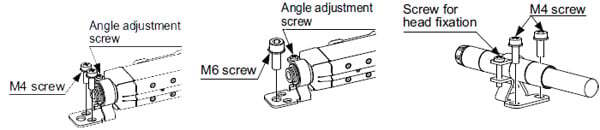
- Using 2 M4 screws or 1 M6 screw, mount the head onto the equipment housing.
- Loosen the angle adjustment screw, adjust the head angle, and then fasten the head with the tightening torque of 0.5 N∙m or less.
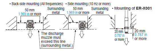
- Position the head mounting bracket of the ER-X001 at least 20 mm 0.787 in away from the tip of the head. The tightening torque for the head fixing screw must be 0.5 N∙m or less.
- After mounting and setting up the head, set the controller according to the procedures described in the instruction manual in order to properly remove electrical charge.
Notes:
1) Be sure to ground the equipment housing onto which the head is mounted.
2) The distance between the head and the charge removing object should be 30 mm 1.181 in or more.
If the static buildup of the charge removing object is 30 kV or more, set the distance to 50 mm 1.969 in or more.
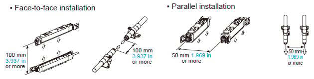
3) If there is metal near the head or between the head and the charge removing object, ion is absorbed, hindering appropriate static removal. Install the head under the following installation condition.
4) In case using the side mounting, the discharge frequency should be 10 Hz or more.
5) When installing two or more heads set the same frequency and keep the distance as below. In face to face or parallel using different frequency, keep the distance between the heads 400 mm 15.748 in or more.
When installing the heads face to face, install heads in distance that the heads can perform the charge removal of a side of the object individualy.
High-voltage unit installation

Controller installation
- Mount the controller on a 35 mm 1.378 in wide DIN rail or using M4 screws.
<When mounting on a DIN rail>
- Pull the lock release lever to remove this product from the DIN rail.

- The tightening torque should be 1.2 N•m or less.

Piping
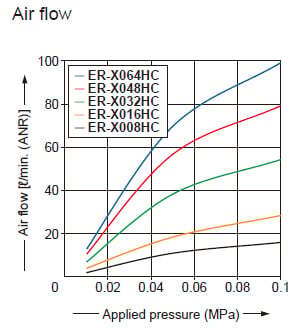
- Air supplied to this product will reduce contamination of the discharge needle and improve the charge removal speed.
- The outer diameter of the air tube to fit to the air inlet portion of this product should be ø6 mm ø0.236 in.
- Make sure that clean air (air containing no water, no oil and no dust) should be supplied.
- Since the pressure will drop when the air piping from the main pressure supply is extended or pneumatic components (e.g., needle valve, speed controller, mini filter) are added, keep an eye on the pressure supply to the ionizer making sure it is not in short supply. For the pneumatic components, select those that can accommodate the air supply flow rate.
ER-X008/X016/X032/X048/X064
<Connection of pipe to head section>

ER-X008HC/X016HC/X032HC/X048HC/X064HC
<Connection of pipe to head section>

ER-X001
<Connection to high-voltage unit>

Note: After inserting the tube into the joint of this product, always make sure that the tube is all the way in and securely inserted.
Insufficient tube insertion will cause air leakage.