Basic Information

Gentle start-up switches in accordance with ergonomics


CE : EMC Directive
UKCA : EMC Regulations

Features
Greater convenience with less stress on the hands.
Inventive start-up switches in accordance with ergonomics. [SW-101]
![Greater convenience with less stress on the hands. Inventive start-up switches in accordance with ergonomics. [SW-101]](https://test-test-test-tp.industry.panasonic.com/hubfs/pid-corp/products/fasys/sensor/safety/sw-101/images/pic02.jpg)
Reduction in false operation from dropped objects [SW-101]
The response time is set for a slight delay so that the switch will not respond a falling object, such as a dropped tool. The switch is designed so that it will operate when touched by hand, but false operation will rarely occur when something is dropped onto it.
![Reduction in false operation from dropped objects [SW-101]](https://test-test-test-tp.industry.panasonic.com/hubfs/pid-corp/products/fasys/sensor/safety/sw-101/images/pic03.jpg)
A switch that pursues the prevention requirement for malfunctioning as required by ISO 13851 (JIS B 9712) two-hand control devices [SW-111]
![A switch that pursues the prevention requirement for malfunctioning as required by ISO 13851 (JIS B 9712) two-hand control devices [SW-111]](https://test-test-test-tp.industry.panasonic.com/hubfs/pid-corp/products/fasys/sensor/safety/sw-101/images/pic04.jpg)
Safeguard prevents false operation
SW-111 saves the hassle of making an additional safeguard. In addition, with its ISO 13851 complying shape, even a knock on the elbow will not cause a false operation (light interruption).

Intended startup is possible [SW-111]
SW-111's detection does not operate when a hand is just placed onto the unit.
With a design that only detects when fingers are bent in and lightly grip onto the unit, an intended startup is possible.
![Intended startup is possible [SW-111]](https://ap.industry.panasonic.com/hubfs/pid-corp/products/fasys/sensor/safety/sw-101/images/pic06.jpg)
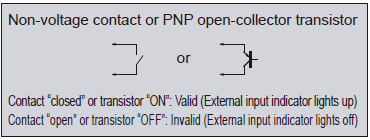
Equipped with external input indicators
Two sets of external input indicators (two colors) are provided, so that they can be used as operation indicators for a variety of purposes.


Option
| Designation | Model No. | Description |
|---|---|---|
| Mounting tool | SW-MT1 | Tool for tightening mounting nuts with a commercially-available wrench. |
| Sensing surface protective sheet for SW-101 | SW-PS1 | A transparent stick-on sheet that protects the sensing surface of SW-101 from dirt and scratches. [5 sheets per set] |
Mounting tool
SW-MT1

Sensing surface protective sheet for SW101

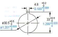
Dimensions
- Unit: mm in
SW-101
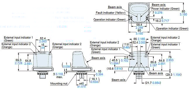
Diagram without mounting nuts installed
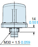
Panel cut-out dimensions
<When mounting with a resin plate>
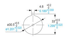
<When mounting with a metal plate>

Note:The panel thickness should be 3 mm 0.118 in or less.
SW-111
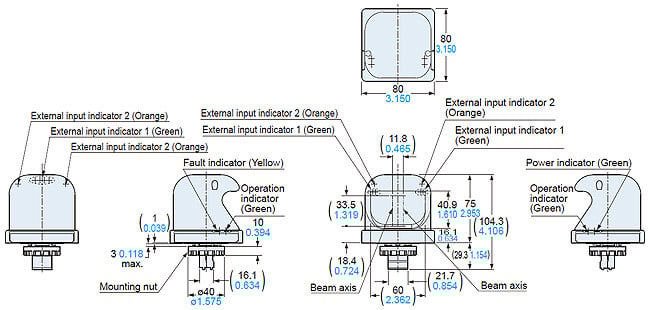
Diagram without mounting nuts installed

Panel cut-out dimensions
<When mounting with a resin plate>
<When mounting with a metal plate>
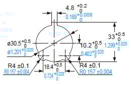
Note:The panel thickness should be 3 mm 0.118 in or less.
I/O Circuit and Wiring diagrams
I/O circuit diagram
If case of connecting output to Minus common

*1
If case of connecting output to Plus common
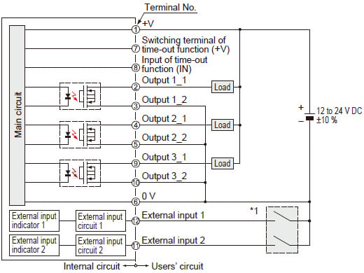
*1

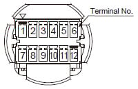
Terminal arrangement diagram
Mounting
- Fasten a mounting nut (accessory) from the reverse side of the mounting plate.(Note 1)
The tightening torque should be 2 to 3 N·m.

Notes:
1) A mounting tool (SW-MT1) for fastening the mounting nut is available separately. The shape of fastening part of SW-MT1 is M10 nut.
2) Make sure to use the attached mounting packing, or waterproof property will be invalid.
Time-out function
- Unintended beam interrupted status caused by dirt on the sensing surface, etc. can be monitored.
When beam interrupted status (sensing status) continues for 10 sec. or more, output 1 turns ON and output 2 and 3 turn OFF (output status is the same as non-sensing status.)
This function can be invalid by short-circuiting “between switching terminals of time-out function (terminal No. 7 and No. 8)” as described below.
Note : When time-out function is operated, the fault indicator (yellow) lights up. In this case, once beam is received, the fault indicator lights off and the sensor returns to normal operation.

Others
- This device has been developed / produced for industrial use only.
- This product is suitable for indoor use only.
- When the power of the thru-beam type photoelectric sensor inside the main body turns on in beam interrupted status, output 1 turns ON and output 2 and 3 turn OFF, then the fault indicator (yellow) lights up. In this case, once beam is received, the fault indicator lights off and the sensor returns to normal operation.
- Use a power supply unit conforming to the EMC Directive and the Low Voltage Directive. (Only for use in Europe)
- Use a power supply unit conforming to Class 2. (Only for use in the North America)
- Use a power supply unit with an output holding time of 20 ms or more.
- Do not use during the initial transient time (300 ms approx.) after the power supply is switched on.