Basic Information
At-a-Glance Recognition of Open / Closed Conditions of All Equipment Doors


UL, CSA : Certified by TÜV SÜD America Inc.
This product uses weak radio waves as the detection principle.
For radio regulations, please refer to the [Notes on SG-P series].
Declaration of Conformity in accordance with the RE Directive (EU law) and the RE Regulations (UK law)
You can be download the Declaration of Conformity from the following link.
>>https://www.ptc.panasonic.eu/compliance-documents(link to external site)![]()
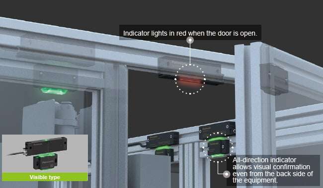
The indicator of the safety switch on the closed door flashes to notify the unsafe condition.


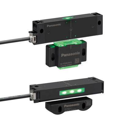
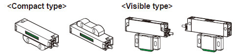
Two Types to Choose from
For doors with aluminum frames
Visible type
For doors without aluminum frames
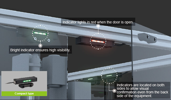
Compact type
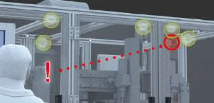
Flashing Function Notifies Unsafe Condition
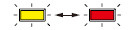
When a door is intentionally kept open, the indicator of the safety switch on that door changes to red and the indicators of the safety switches on all other doors flash in green.
The operator can recognize immediately the equipment status and which door is open.
BEFORE Conventional system
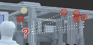
When one of the doors was kept open, the indicators of all other interlocked safety switches turned off so there was no way of knowing which door was open without checking each door.
When the safety switch was installed on the inner side of the door, the indicator of the safety switch was not visible from the outside of the equipment area in some cases.

[Industry’s First*] AFTER SG-P series
* As of September 2020, in-company survey
The indicator of the safety switch on the open door changes to red and the indicators on all other doors flash in green.
The operator can recognize immediately the equipment status and which door is open.


The visible type actuator allows the light from the switch body to pass through so that the indicator light is visible from the actuator side.
This ensures high visibility of the safety switches installed on doors with aluminum frames.
* Industry’s first safety door switches with this function as of October 2020, in-company survey.
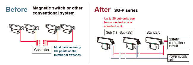
Master-Slave (Standard / Sub) System for Reduced Wiring
Serial Connection of Up to 30 Units without Dedicated Controller
The SG-P series standard units, which are used as master units, can output safety signals all at once (OSSD1 / OSSD2).
The sub units used as slave units minimize the wiring for a cascade connection.
There is no need to purchase a dedicated controller. The presently used safety controller / circuit can be connected directly. Up to 30 units can be connected, thus contributing to wire-saving.
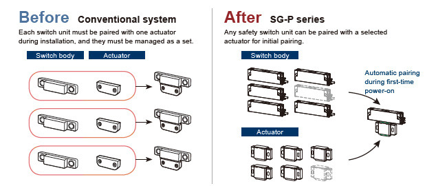
No Cumbersome Manual Pairing Necessary before Installation
* High-code models (SG-P20□-M-□, SG-P20□-S) only
During the initial setting, bring the switch body close to the actuator and turn on the power to let the safety switch detect the actuator for 3 seconds. This simple procedure completes the pairing. In a cascade connection, pairing can be achieved all at once by simply turning on the power. This reduces the man-hours required for starting up the equipment.
* Low-code models (SG-P10□-M-□, SG-P10□-S) do not require pairing.
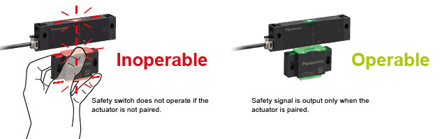
Helps Prevent Intentional Deactivation of Safety Function
The ISO 14119:2013* international standard stipulates a design requirement that deactivations of safety functions shall be minimized.
Export of equipment sometimes requires to meet this standard. The SG-P series products are available with two different coding levels: High-code models and Low-code models. The High-code models are compatible with ISO 14119:2013* coding level (high level coded actuators) and prevent intentional deactivation of their safety function.
* ISO 14119:2013
Safety of machinery – Interlocking devices associated with guards – Principles for design and selection
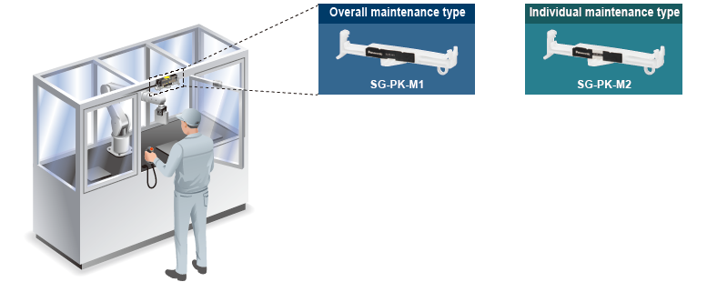
Maintenance Actuator (sold separately) for Facilitating Maintenance Work
Designed for one-touch installation, the maintenance actuator generates a signal to switch the control mode.
The maintenance actuator mounts on the SG-P series and generates a signal to switch the control mode. This signal can be used as a trigger to restrict machine operation. Two types of maintenance actuator are available: overall maintenance type (SG-PK-M1) and individual maintenance type (SG-PK-M2).
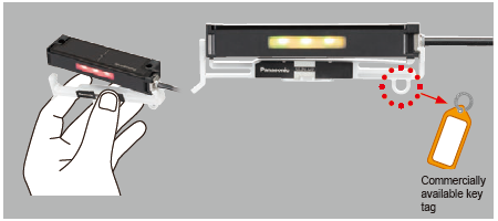
One-touch installation
Indicating the name of the department that owns the maintenance actuator and the name of person in charge on a commercially available key tag and attaching it to each unit makes it easy to manage the users.
* Individual maintenance type actuator (SG-PK-M2) is mounted on a compact type unit in the above example.
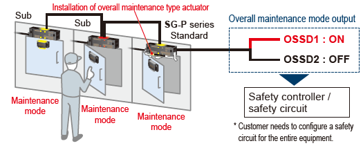
[Overall maintenance type (SG-PK-M1)]
The source of hazard in a hazardous area can be accessed from any door. OSSD1 maintains ON status regardless of which door is opened.
* Be sure to evaluate the control output correctly.
* Can be used only with the standard switch body.
* All switch bodies in series connection change to the maintenance mode.
* The indicators on the switch bodies in series connection change in color.
* All doors with the switch bodies in series connection can be opened and closed. Take care not to allow unauthorized persons to open or close the doors.
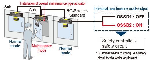
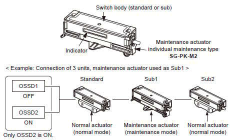
[Individual maintenance type (SG-PK-M2)]
The source of hazard in a hazardous area can be accessed from the specified door. When any other door is opened, OSSD2 also turns OFF.
* Be sure to evaluate the control output correctly.
* Can be used with the standard or sub switch body.
* Can be installed to multiple switch bodies for simultaneous use.
* Only the switch bodies installed with this product type can be individually changed to the maintenance mode.
* The indicators on the switch bodies in series connection change in color.
Large and Bright Indicator for the Notification of Maintenance Mode Status to Workers
When the SG-P unit is mounted with the maintenance actuator, the large indicator lights in "yellow".
The workers can readily recognize that the equipment is in maintenance.
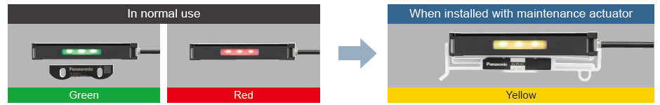
* Compact type unit is shown above as an example.
[Notes on SG-P series]
*As of April 21, 2026
- This product uses weak radio waves as the detection principle.
Therefore, the countries and regions where this product can be used are limited to Japan, China, Europe, the United States, Canada, Singapore, Thailand, Korea, India, Philippines, Indonesia, Malaysia, Vietnam and Taiwan Region.
Refer to the "Order Guide" page for information on Taiwan NCC certification.

- This product complies with the European RE Directive and the Mechanical Directive.
The instruction manuals are available in nine languages: Japanese, English, Chinese(Simplified), Chinese(Traditional), German, French, Thai, Korean and Spanish.
Be aware of the legal requirements of the country where the product is exported or used, and use the instructions in the appropriate language.


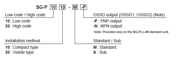
Order guide
Model No.
Product type
Compact type
[Standard]
・SG-P1010-M-P
・SG-P1010-M-N
・SG-P2010-M-P
・SG-P2010-M-N
[Sub]
・SG-P1010-S
・SG-P2010-S
Visible type
[Standard]
・SG-P1020-M-P
・SG-P1020-M-N
・SG-P2020-M-P
・SG-P2020-M-N
[Sub]
・SG-P1020-S
・SG-P2020-S
Notes:
1) Sub units cannot be used alone. When using a single unit, use a standard unit. When using multiple units in series connection, combine a standard unit with sub units.
2) The switch body must be connected to a power supply unit and a safety device such as a safety controller. Power supply unit and safety controller must be purchased separately.
Order guide
| Coding level | Type (Note) | Model No. | Control output (OSSD1, OSSD2) | Cable length | |
|---|---|---|---|---|---|
| Low code | Compact type | Standard | SG-P1010-M-P | PNP open-collector transistor, 2 outputs | 5 m 16.404 ft |
| SG-P1010-M-N | NPN open-collector transistor, 2 outputs | ||||
| Sub | SG-P1010-S | - | 3 m 9.843 ft | ||
| Visible type | Standard | SG-P1020-M-P | PNP open-collector transistor, 2 outputs | 5 m 16.404 ft | |
| SG-P1020-M-N | NPN open-collector transistor, 2 outputs | ||||
| Sub | SG-P1020-S | - | 3 m 9.843 ft | ||
| High code | Compact type | Standard | SG-P2010-M-P | PNP open-collector transistor, 2 outputs | 5 m 16.404 ft |
| SG-P2010-M-N | NPN open-collector transistor, 2 outputs | ||||
| Sub | SG-P2010-S | - | 3 m 9.843 ft | ||
| Visible type | Standard | SG-P2020-M-P | PNP open-collector transistor, 2 outputs | 5 m 16.404 ft | |
| SG-P2020-M-N | NPN open-collector transistor, 2 outputs | ||||
| Sub | SG-P2020-S | - | 3 m 9.843 ft | ||
(Note) : Sub units cannot be used alone. When using a single unit, use a standard unit. When using multiple units in series connection, combine a standard unit with sub units.
Taiwan NCC certification information: certification number list
* Conformed from April 2025 production.
| Model No. | Certification number |
|---|---|
| SG-P1010-M-P | CCAJ23LP0549T0 |
| SG-P1010-M-N | CCAJ23LP054AT7 |
| SG-P1010-S | CCAJ23LP054BT9 |
| SG-P1020-M-P | CCAJ23LP0546T4 |
| SG-P1020-M-N | CCAJ23LP0547T6 |
| SG-P1020-S | CCAJ23LP0548T8 |
| SG-P2010-M-P | CCAJ23LP0543T1 |
| SG-P2010-M-N | CCAJ23LP0544T0 |
| SG-P2010-S | CCAJ23LP0545T2 |
| SG-P2020-M-P | CCAJ23LP0540T5 |
| SG-P2020-M-N | CCAJ23LP0541T7 |
| SG-P2020-S | CCAJ23LP0542T9 |
Options (Sold separately)
| Type | Model No. | |
|---|---|---|
| Maintenance actuator | Overall maintenance type | SG-PK-M1 |
| Individual maintenance type | SG-PK-M2 | |
Maintenance actuator
・SG-PK-M1
・SG-PK-M2
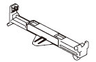
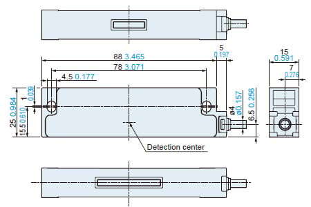
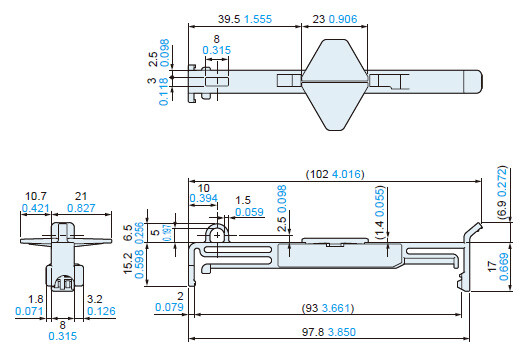
Dimensions
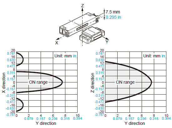
- Unit: mm in
SG-P□10-M-□ SG-P□10-S
Compact type
Switch body
Actuator (accessory)

SG-P□20-M-□ SG-P□20-S
Visible type
Switch body
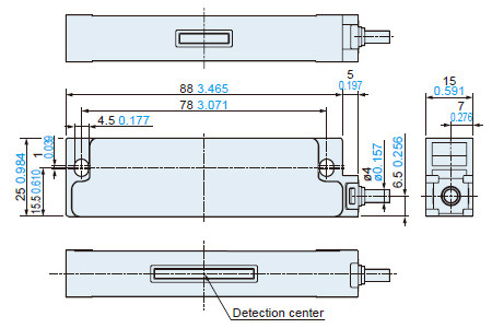
Actuator (accessory)
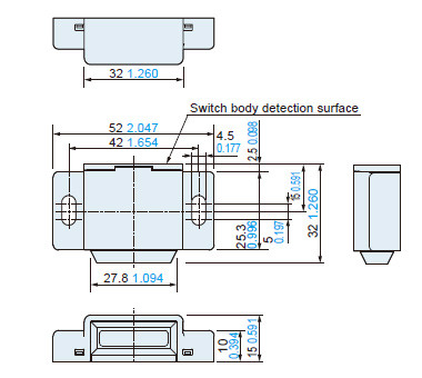
SG-PK-M1 SG-PK-M2
Maintenance actuator (optional)
I/O Circuit and Wiring diagrams
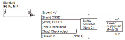
Using only one unit
* Sub unit SG-P□-S cannot be used alone.
<PNP output type / SG-P□-M-P>
<NPN output type / SG-P□-M-N>
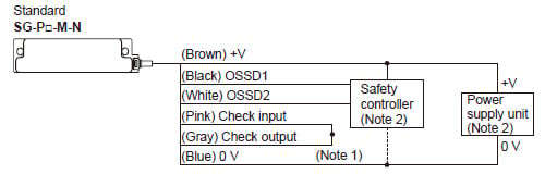
Notes :
1) : Connect the check input line (pink) with the check output line (gray).
2) : The switch body must be connected to a power supply unit and a safety device such as a safety controller. Power supply unit and safety controller must be purchased separately.
・Maximum cable length
The cable connected between the switch body and power supply unit must not exceed 20 m 65.617 ft.
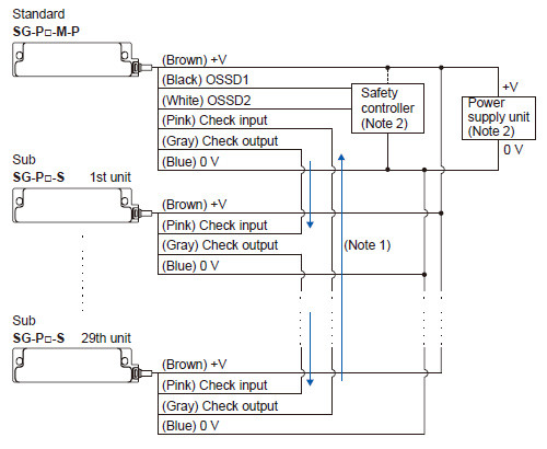
Using multiple units in series connection
One standard unit (SG-P□-M-P / SG-P□-M-N) can be connected with up to 29 SG-P□-S sub units in series.
<PNP output type / SG-P□-M-P>
<NPN output type / SG-P□-M-N>
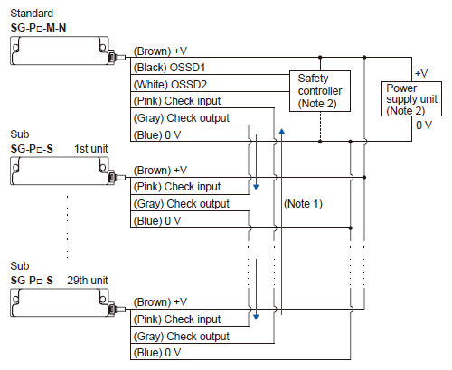
Notes :
1) : For connecting multiple units, connect the check output line (gray) with the check input line (pink) of the SG‑P□‑S sub unit connected next. Connect the check output line (gray) of the SG‑P□‑S sub unit connected at the end with the check input line (pink) of the standard unit (SG-P□-M-P / SG-P□-M-N) placed at the beginning
2) : The switch body must be connected to a power supply unit and a safety device such as a safety controller. Power supply unit and safety controller must be purchased separately.
Total / maximum cable length of check input / output cables
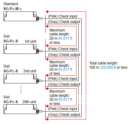
The total length of the cables connected from the SG-P□-M-□ standard unit to the last SG-P□-S sub unit (farthest from the standard unit) must not exceed 100 m 328.084 ft. The cable connected from each switch body to the adjacent switch body must not exceed 20 m 65.617 ft.
・Total / maximum cable length of power cables and OSSD cables
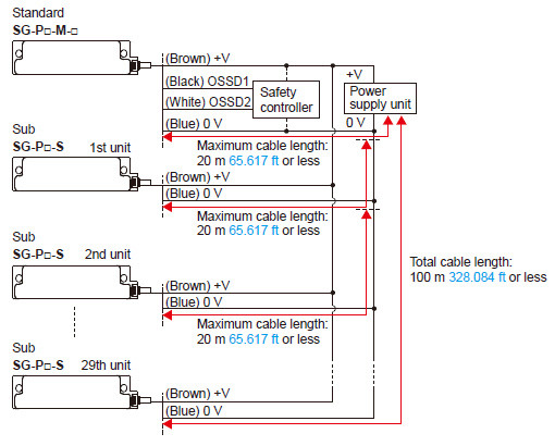
The total length of the cables between the switch bodies and power supply unit and the total length of the cables between the switch bodies and safety control unit must not exceed 100 m 328.084 ft each. The cable connected from each switch body to the adjacent switch body must not exceed 20 m 65.617 ft.
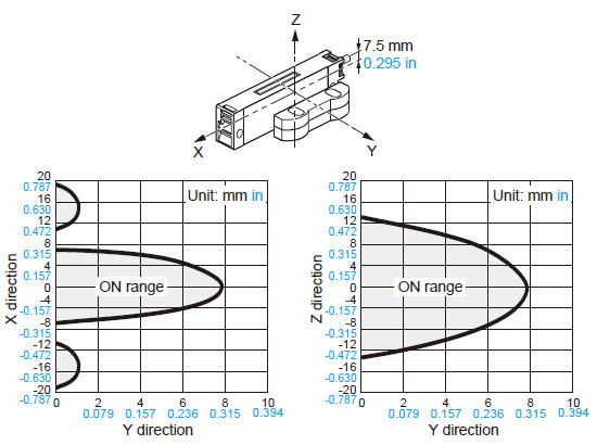
Sensing characteristics
SG-P□10-M-□ SG-P□10-S
Compact type
Sensing field
SG-P□20-M-□ SG-P□20-S
Visible type
Sensing field
- This product has been developed / produced for industrial use only.
- This product is suitable for indoor use only.
- This product is an extremely low power radio device and complies with the Japanese Radio Act. There is no need to obtain a radio station license to use the product in Japan.
- Do not use this product near equipment that emits strong electromagnetic waves.
- If the power supply used for this device is shared by other devices, the device may be affected by noise emitted from other devices. Do not share the power supply used for this device with other devices.
- The switch body of this product must be connected to a power supply unit and a safety device such as a safety controller. Power supply unit and safety controller must be purchased separately.
- The power supply unit used for this device must satisfy the following requirements.
- The power supply unit must be certified for use in your region.
- The power supply unit must have the rated output voltage of 24 V DC +10-20 % and the ripple (P-P) of 10 % or less.
- The power supply with SELV (Secondary Extra Low Voltage) or PELV (Protective Extra Low Voltage) that comply with the RE Directive must be used. (When CE Marking is required)
- The power supply must comply with Class 2 defined by UL508 or satisfy the output characteristics requirements of the limited voltage and current circuit.
- The power supply unit must have reinforced insulation or double insulation between the primary circuit and secondary circuit.
- When using a commercial switching regulator, the frame ground (F.G.) terminal must be connected to ground.
- The power supply unit must have an output holding time of 20 ms or more.
- If surges occur, take countermeasures such as connecting a surge absorber to the source of the surges.
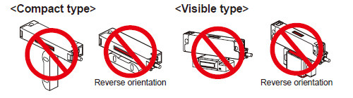
Mounting
- Do not install the switch body of this device on a movable door.
- Mount the switch body carefully so that it does not come in contact with the movable door.
- Mount the switch body in a location where it cannot be reached or it is hidden so that it cannot be easily disabled. Or, mount the switch body in such a way that it cannot be removed with ordinary tools.
Correct mounting orientation
Incorrect mounting orientation
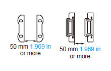
Mutual Interference
When multiple devices are installed next to one another, mutual interference may occur and cause malfunctioning. When using them next to one another, provide a distance between one another as shown below.
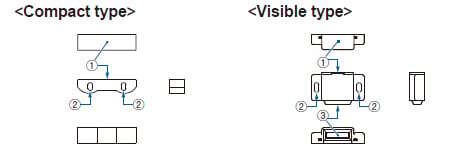
Switch body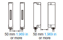
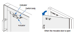
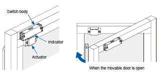
Part description
Switch body
| No. | Name | Function | |
|---|---|---|---|
| ① | Indicator | Lights green
| When the actuator is detected |
| Lights red
| When the actuator is not detected | ||
| Blinks red
| • Lockout state, error occurrence • When the teaching sequence was incorrect (only when using highcode models SG-P20□-□) | ||
| Blinks green
| When other switch bodies (standard unit, sub unit) in series connection do not detect actuators, when error occurs | ||
| Lights yellow
(Simultaneously light green and red) (Note) | After the power supply is turned ON, during self-diagnosis | ||
| Alternately blinking red to yellow
(lights red, blinking green) (Note) | When an unpaired actuator is detected (only when using highcode models SG-P20□-□) | ||
| ② | Actuator detection surface | When the actuator is brought near to the surface, the switch body detects the actuator. | |
| ③ | Mounting hole | Use M4 screws (length: 20 mm 0.787 in or more), flat washers and spring washers (not supplied with the product) to install the switch body to the equipment body or guard. The screws should be tightened with a torque of 1.2 N∙m. | |


Note : When you look at a lit LED on a visible type model through the actuator, the LED may sometimes appear green in some part and red in other part.
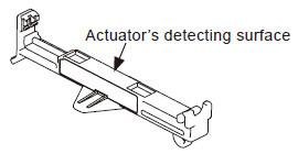
Actuator
| No. | Name | Function |
|---|---|---|
| ① | Switch body detection surface | When the actuator is brought near to the switch body, the switch body detects the actuator. |
| ② | Mounting hole | Use M4 screws (length: 20 mm 0.787 in or more), flat washers and spring washers (not supplied with the product) to install the actuator to the door. The screws should be tightened with a torque of 1.2 N∙m. |
| ③ | Transmission part | The light of the indicator is transmitted through the part. |
About maintenance actuators (optional)
By directly mounting the maintenance actuator to the switch body while the door is open, it is possible to distinguish accidental opening of the door. Two types of maintenance actuators are available: overall maintenance type (SG-PK-M1) and individual maintenance type (SG-PK-M2 (Note)).
Note: In the case of the individual maintenance type SG-PK-M2, multiple units can be installed and used simultaneously.
| Type | Overall maintenance type | Individual maintenance type |
|---|---|---|
| Model No. | SG-PK-M1 | SG-PK-M2 |
| Ambient temperature | 0 to +40 ℃ 0 to +104 ℉ (No dew condensation), Storage: -25 to +65 ℃ -13 to +149 ℉ | |
| Ambient humidity | 35 to 85 % RH, storage: 35 to 85 % RH | |
| Vibration resistance | 10 to 55Hz, 1 mm double amplitude, 2 hours each in X, Y, and Z directions | |
| Shock resistance | 300 m/s2 (30 G approx.), 3 times each in X, Y, and Z direction | |
| Material | POM (polyacetal) | |
| Weight | 7 g approx. | |
・Overall maintenance type (SG-PK-M1) can be used only on standard switch bodies.
・Individual maintenance type (SG-PK-M2) can be used on standard and sub switch bodies.
・When maintenance actuators are used, redundant input monitoring (dual channel monitoring) of OSSD1and OSSD2 for the SG-P series by a safety controller, etc. cannot be used.
・When using a maintenance actuator, be careful that the normal actuator will not be detected at the same time.
・Determine whether to use the normal mode or maintenance mode according to the system.
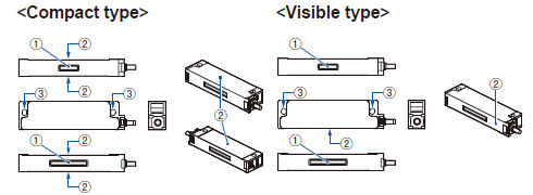
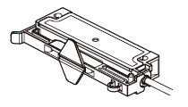
Installation
Installation on compact type unit
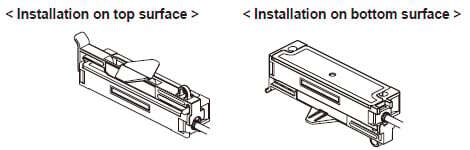
Installation on visible type unit
Output operation and indicator operation
Operation differs between the overall maintenance type (SG‑PK‑M1) and individual maintenance type (SG‑PK‑M2). The output operation and indicator operation of the switch body when used with each maintenance actuator is as follows
When using overall maintenance type actuator (SG-PK-M1)
The SG-PK-M1 can only be used on standard switch bodies.
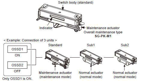
Note:Individual maintenance type (SG-PK-M2) cannot be used when overall maintenance type is used.
| Type | Standard | Sub1 | Sub2 | OSSD1 | OSSD2 | |||||||
|---|---|---|---|---|---|---|---|---|---|---|---|---|
| Actuator | Detection Status | Indicator | Actuator | Detection Status | Indicator | Actuator | Detection Status | Indicator | ||||
| Overall Mainte- nance | Mainte- nance | Detection | Yellow | Normal | Detection | Yellow | Normal | Detection | Yellow | ON | OFF | |
| Detection | Yellow | Detection | Yellow | Not detected | Red | ON | OFF | |||||
| Detection | Yellow | Not detected | Red | Detection | Yellow | ON | OFF | |||||
| Not detected | Red | Detection | Blinks green | Detection | Blinks green | OFF | OFF | |||||
| After 12 hours (Note 1) | Detection | Blinks yellow/ red | Detection | Blinks yellow/ red | Detection | Blinks yellow/ red | OFF | OFF | ||||
Notes:
1) Maintenance actuator can operate continuously for up to 12 hours. After 12 hours, OSSD1 turns OFF automatically and the indicator on the switch body blinks in yellow / red. To use the maintenance actuator again, detach the actuator and reinstall.
2) The indicator on the switch body blinks in yellow or red to indicate one of the two modes. For details, see the Instruction Manual of the SG-P series.
When using individual maintenance type actuator (SG-PK-M2)
The SG-PK-M2 can be used for standard and sub switch bodies.
| Type | Standard | Sub1 | Sub2 | OSSD1 | OSSD2 | |||||||
|---|---|---|---|---|---|---|---|---|---|---|---|---|
| Actuator | Detection Status | Indicator | Actuator | Detection Status | Indicator | Actuator | Detection Status | Indicator | ||||
| Indi- vidual Mainte- nance | Normal | Detection | Yellow | Mainte- nance | Detection | Yellow | Normal | Detection | Yellow | OFF | ON | |
| Not detected | Red | Detection | Blinks yellow/ red | Detection | Blinks yellow/ red | OFF | OFF | |||||
| Detection | Blinks green | Not detected | Red | Detection | Blinks green | OFF | OFF | |||||
| After 12 hours (Note) | Detection | Blinks yellow/ red | Detection | Blinks yellow/ red | Detection | Blinks yellow/ red | OFF | OFF | ||||
Note : Maintenance actuator can operate continuously for up to 12 hours. After 12 hours, OSSD2 turns OFF automatically and the indicator on the switch body blinks in yellow / red. To use the maintenance actuator again, detach the actuator and reinstall.