Discontinued Products

Dimensions
- Unit: mm in
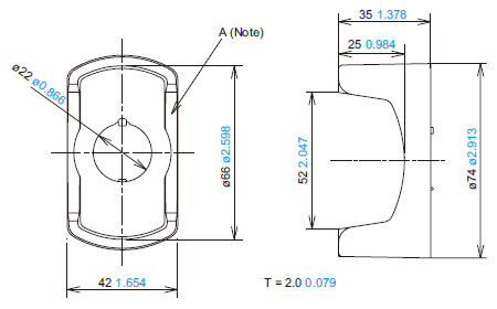
SG-E1-□
Emergency stop switch
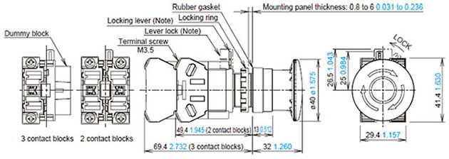
Note: Please attach the lever lock (yellow) after locking to prevent personnel from forgetting to lock the lock lever.
SG-E1-□-E
SEMI emergency off (EMO) switch
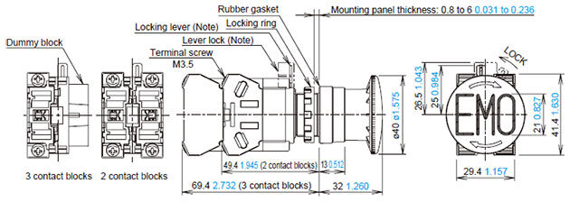
Note: Please attach the lever lock (yellow) after locking to prevent personnel from forgetting to lock the lock lever.
SG-EP□
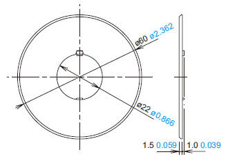
Emergency stop nameplate (Optional)
SG-ET1
Locking ring wrench (Optional)
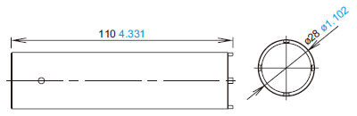
MS-SG-GR1
SEMI guard ring (Optional)
Note: When anti-rotation is not required or when the panel cut-out does not have an anti-rotation recess, remove part “A” of the SEMI guard ring using pliers.
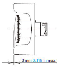
Height of SEMI emergency off (EMO) switch and SEMI guard ring
As illustrated below, the height of the SEMI emergency off (EMO) switch and SEMI guard ring should be 3 mm 0.118 in or less.
Note
The EMO switch and the guard ring have been designed for applications in semiconductor manufacturing equipment only. Do not use EMO switch and/or the guard ring which are installed on machine tools or food processing machines.
(Machinery Directive of the European Commission and IEC 60204- 1 require that emergency stop switches be installed in a readily accessible area and the usage of switch guards is not permitted.)
Mounting hole layout / minimum mounting center
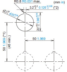
Note:When using the safety lever lock,determine the vertical spacing(*1) in consideration of convenience for installing and removing the safety lever lock. (Recommended vertical spacing: 100 mm 3.937 in or more)
The 3.2+0.200.126+0.0080 recess(*2) is for preventing rotation and not necessary when anti-rotation is not used.
When anti-rotation is not required or when the panel cut-out does not have anti-rotation recess, remove the "Projection" using pliers.
- The minimum mounting centers are applicable to switches with one layer of contact blocks (two contact blocks). When two layers of contact blocks are mounted, determine the minimum mounting centers in consideration of convenience for wiring.
Applicable wiring
(1) The applicable wire size is 2 mm2 maximum. (single wire ø1.6 mm ø0.063 in maximum) One or two wires can be connected.
・Applicable crimping terminal (Unit: mm in)
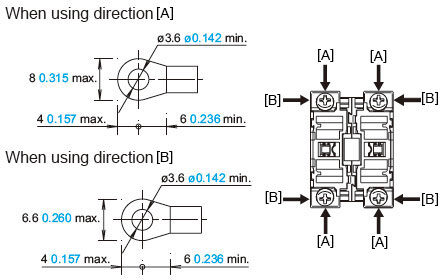
Be sure to use an insulation tube or cover on the crimping part of the crimping terminal to prevent electrical shocks.
・Single wire (Unit: mm in)
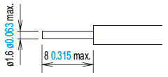
Note: When connecting wires to contact blocks or transformers in the direction [B], keep the insulation stripping length 6.6 mm 0.260 in at the maximum.
(2) Tighten the M3.5 terminal screws to a torque of 1.0 to 1.3 N・m.
Using the lever lock
・Panasonic Industry strongly recommends using the lever lock (yellow) to prevent heavy vibration or maintenance personnel from unlocking the contact assembly.
Using SEMI guard rings
SEMI guard rings[MS-SG-GR1] are designed specifically for use with semiconductor manufacturing equipment and should not be used as emergency stop switches for machine tools, food processing machinery, or other equipment.
(The European Machinery Directive, IEC 60204-1, JIS B9960-1, and other standards require that emergency stop switches be easy to approach and operate, and use of SEMI standard-compliant switch guards is not currently approved.