Discontinued Products
Specifications
| Model No. | Position | Contact configuration | Contact block | Operation position | Key removal Mounting position | ||
|---|---|---|---|---|---|---|---|
| Mounting position (Note) | Contact | 1 | 2 | ||||
| SG-D1-2A11 |
| 1NO/1NC (11) | [1] | NO | ● |
| |
| [2] | NC | ● | |||||
| SG-D1-2A22 | 2NO/2NC (22) | [1] | NO | ● | |||
| [2] | NC | ● | |||||
| [3] | NO | ● | |||||
| [4] | NC | ● | |||||
| SG-D1-2B11 | 1NO/1NC (11) | [1] | NO | ● |
| ||
| [2] | NC | ● | |||||
| SG-D1-2B22 | 2NO/2NC (22) | [1] | NO | ● | |||
| [2] | NC | ● | |||||
| [3] | NO | ● | |||||
| [4] | NC | ● | |||||
| SG-D1-2C11 | 1NO/1NC (11) | [1] | NO | ● |
| ||
| [2] | NC | ● | |||||
| SG-D1-2C22 | 2NO/2NC (22) | [1] | NO | ● | |||
| [2] | NC | ● | |||||
| [3] | NO | ● | |||||
| [4] | NC | ● | |||||
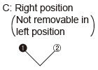
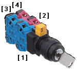
Note: Contact blocks are attached as shown below:
| Designation | Key selector switch | |||||||||
|---|---|---|---|---|---|---|---|---|---|---|
| Series | SG-D1 series | |||||||||
| Applicable standards | JIS C 8201-5-1, IEC 60947-5-1, EN 60947-5-1, UL 508 (UL listed Certification), CSA 22.2 No.14 (c-UL listed Certification) | |||||||||
| Operating condition | Ambient temperature | -25 to +60℃ -13 to + 140 ℉ (No dew condensation or icing allowed) Storage: -40 to +80 ℃ -40 to +176 ℉ | ||||||||
| Ambient humidity | 45 to 85 % RH | |||||||||
| Pollution degree | 3 | |||||||||
| Altitude | 2,000 m 6,561.68 ft max. | |||||||||
| Impulse withstand voltage (Uimp) | 4 kV | |||||||||
| Rated insulation voltage (Ui) | 600 V | |||||||||
| Thermal current (Ith) | 10 A | |||||||||
| Rated operational voltage (Ue) / Rated operational current (Ie) | Ue | |||||||||
| 24V | 48V | 50V | 110V | 220V | 440V | |||||
| Ie | AC | Resistive load (AC-12) | 10A | - | 10A | 10A | 6A | 2A | ||
| Inductive load (AC-15) (A600)) | 10A | - | 7A | 5A | 3A | 1A | ||||
| DC | Resistive load (DC-12) | 8A | 4A | - | 2.2A | 1.1A | - | |||
| Inductive load (DC-13) (P600) | 4A | 2A | - | 1.1A | 0.6A | - | ||||
| Contact resistance | 50 mΩ max. (initial value) | |||||||||
| Insulation resistance | 100 MΩ min. (500 V DC megger) | |||||||||
| Electric shock protection class | Class II(IEC 61140) | |||||||||
| Overvoltage category | II(IEC 60664-1) | |||||||||
| Protection | Front of the panel: IP65 | |||||||||
| Shock resistance | Malfunction: 100 m/s2, Destruction: 1,000m/s2 | |||||||||
| Vibration resistance | Malfunction: 5 to 55 Hz, half amplitude 0.5 mm 0.020 in Destruction: 30 Hz, half amplitude 1.5 mm 0.059 in | |||||||||
| B10d | 100,000 (ISO 13849-1 Annex C Table C.1) | |||||||||
| Mechanical durability | 100,000 operations min. | |||||||||
| Electrical durability | 100,000 operations min. (1,200 operations/hour) | |||||||||
| Material | Actuator: PA6, Contact block: PA66 | |||||||||
| Connecting method | Terminal screw (M3.5 philips & flathead ) | |||||||||
| Applicable wire size | Max.2mm2(Single core ø1.6 ø0.063 max.) 2 wires max. | |||||||||
| Tightening torque of the terminal screws | 1.0 to 1.3 N・m | |||||||||
| Tightening torque of the locking ring | 2.0 N・m | |||||||||
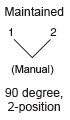
| Selector behavior | 2 positions | |||||||||
| Minimum direct opening operating angle | 90° | |||||||||
| Minimum direct opening torque | 0.4 N・m | |||||||||
| Maximum operation angle | 90° | |||||||||
| Weight | SG-D1-2□11: Approx. 75 g, SG-D1-2□22:Approx. 95 g | |||||||||
| Accessories | Key: 2pcs., Lever lock: 1 pc. | |||||||||
Dimensions
- Unit: mm in
SG-D1-□
Key selector switch
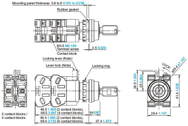
Note: Please attach the lever lock (yellow) after locking to prevent personnel from forgetting to lock the lock lever.
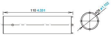
SG-ET1
Locking ring wrench (Optional)
Mounting hole layout / minimum mounting center

Note: When using the safety lever lock, determine the vertical spacing(*1) in consideration of convenience for installing and removing the safety lever lock. (Recommended vertical spacing: 100 mm 3.937 in or more)
The 3.2+0.200.126+0.0080recess(*2) is for preventing rotation and not necessary when anti-rotation is not used.
- The minimum mounting centers are applicable to switches with one layer of contact blocks (two contact blocks).
When two layers of contact blocks are mounted, determine the minimum mounting centers in consideration of convenience for wiring.
Applicable wiring
(1) The applicable wire size is 2 mm2 maximum. (single wire ø1.6 mm ø0.063 in maximum) One or two wires can be connected.
・Applicable crimping terminal (Unit: mm in)

Be sure to use an insulation tube or cover on the crimping part of the crimping terminal to prevent electrical shocks.
・Single wire (Unit: mm in)

Note: When connecting wires to contact blocks or transformers in the direction [B], keep the insulation stripping length 6.6 mm 0.260 in at the maximum.
(2) Tighten the M3.5 terminal screws to a torque of 1.0 to 1.3 N・m.
Using the lever lock (accessory)
・Please attach the lever lock (yellow) after locking to prevent personnel from forgetting to lock the lock lever.