Basic Information
Introducing a safety door switch with solenoid interlock that is among the world's thinnest class*!


Features
Introducing a safety door switch with solenoid interlock that is among the world’s thinnest class*! With 5 built-in contacts
* Based on research conducted by our company as of May 2025.

Space saving design with angled connection cable
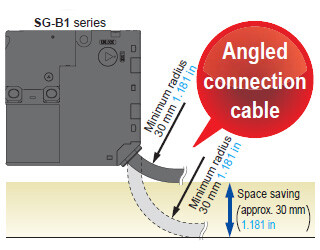
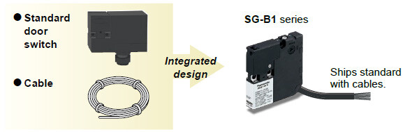
SG-B1 series come with cables pre-installed.
The SG-B1 series ship with bundled cables already connected internally.
Since there is no need to provide cables separately, and because they are already connected internally, the number of wiring man-hours is cut in half.
Can be installed on any door.
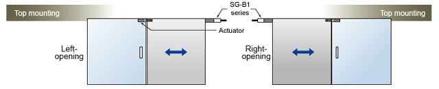
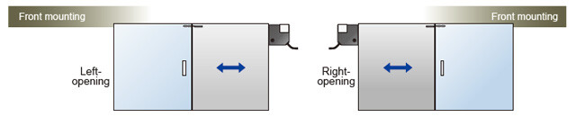
Sliding doors
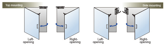
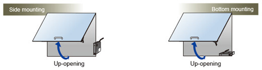
Hinged doors
Choose between two types of locks
・Spring lock
・Magnet lock
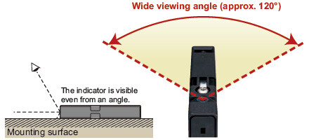
Easy-to-see LED operation indicator
SG-K11

SG-K12

SG-K12A

SG-K13

SG-K14

Dimensions
- Unit: mm in
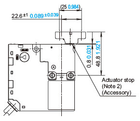
SG-B1□
Safety door switch with solenoid interlock
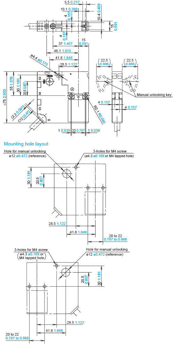
Note 1: Drill mounting holes so that they are properly aligned for the orientation in which the safety switch will be used.
When using straight actuator (SG-K11)
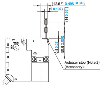
Notes: 2) The actuator stop is used to adjust the actuator position. Remove the actuator stop after the actuator position is mounted.
When using the right-angle actuator (SG-K12 / SG-K12A)
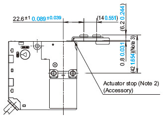
Notes:
2) The actuator stop is used to adjust the actuator position. Remove the actuator stop after the actuator position is mounted.
3) 41.4 1.63 when using SG-K12*The tensile strength of the SG-K12 actuator is 100N. If an excessive tensile force is applied, the actuator may fall off the door.When a tensile force exceeding 100N is expected, use the SG-K12A actuator with a plate.
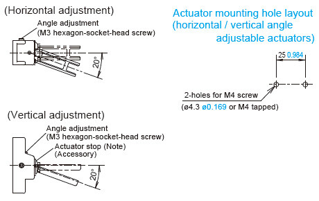
When using the angle adjustable actuator (horizontal / vertical) (SG-K13 / SG-K14)
Notes: 2) The actuator stop is used to adjust the actuator position. Remove the actuator stop after the actuator position is mounted.
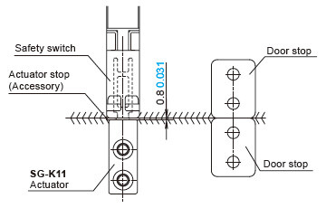
Actuator mounting reference position
As shown in the figure on the right, the mounting reference position of the actuator when inserted in the safety switch is:
The actuator stop on the actuator lightly touches the safety switch.
* The actuator stop is used to adjust the actuator position. Remove the actuator stop after the actuator position is mounted.
SG-K11
Actuator
Straight actuator
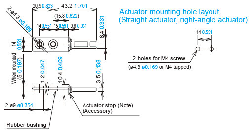
Note: The actuator stop is used to adjust the actuator position. Remove the actuator stop after the actuator position is mounted.
SG-K12
Actuator
Right-angle actuator
* The tensile strength of the SG-K12 actuator is 100N. If an excessive tensile force is applied, the actuator may fall off the door.
When a tensile force exceeding 100N is expected, use the SG-K12A actuator with a plate.

Note: The actuator stop is used to adjust the actuator position. Remove the actuator stop after the actuator position is mounted.
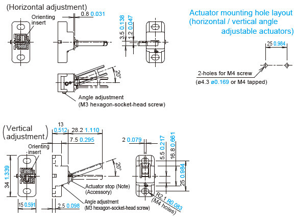
SG-K13
Actuator
Horizontal / vertical angle adjustable actuators (SG-K13)
* The base is made of glass-reinforced PA66 (66 nylon). Angle adjustment screws are stainless steel (SUS).
When using adhesive on screws, take material compatibility into consideration.
Note: The actuator stop is used to adjust the actuator position. Remove the actuator stop after the actuator position is mounted.
SG-K14
Actuator
Horizontal / vertical angle adjustable actuators (SG-K14)
* The SG-K14 differs from the SG-K13 in that the direction in which the metal parts on the tip of the actuator are embedded is reversed by 180°.
Note: The actuator stop is used to adjust the actuator position. Remove the actuator stop after the actuator position is mounted.
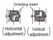
Changes in the orientation of adjustment for angle adjustable (horizontal / vertical) actuators
The orientation of actuator adjustment (horizontal / vertical) can be changed using the orienting insert (white plastic) installed on the back of the actuator.
Do not lose the mounting plate.
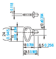
Manual unlocking key (Accessory: plastic)
- Regardless of door types, do not use the safety switch as a door stop. Install a mechanical door stop at the end of the door to protect the safety switch against excessive force.
- Do not apply external force on the actuator while unlocking, otherwise the actuator may not be unlocked.
- Do not apply excessive shock to the safety switch when opening or closing the door. A shock to the safety switch exceeding 1,000 m/s2 may cause damage to the safety switch.
- If the operating atmosphere is contaminated, use a protective cover to prevent the entry of foreign objects into the safety switch through the actuator entry slots. Entry of a considerable amount of foreign objects into the safety switch may affect the mechanism of the safety switch and cause a malfunction.
- Do not store the safety switches in a dusty, humid, or organic-gas atmosphere, or in an area subjected to direct sunlight.
- Use proprietary actuators only. When other actuators are used, the safety switch may be damaged.
- The locking strength is rated at 500 N. Do not apply a load higher than the rated value. When a higher load is expected, provide an additional system consisting of another safety switch without lock (such as the SG-A1 safety switch) or a sensor to detect door opening and stop the machine.
- Regardless of door types, do not use the safety switch as a door lock. Install a separate lock using a latch or other measures.
- While the solenoid is energized, the switch temperature rises approximately 35 ℃ 95 ℉ above the ambient temperature (to approximately 85 ℃ 185 ℉ while the ambient temperature is 50 ℃ 122 ℉). Do not touch to prevent burns. If cables come into contact with the switch, use heat-resistant cables.
- Bouncing will occur on the lock monitor contact during locking and unlocking (reference value: 20 ms).
- Although the SG-K11 / SG-K12 / SG-K12A actuators alleviate shock when the actuator enters a slot in the safety switch, make sure that excessive shock is not applied. If the rubber bushings become deformed or cracked, replace with new ones.
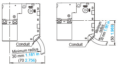
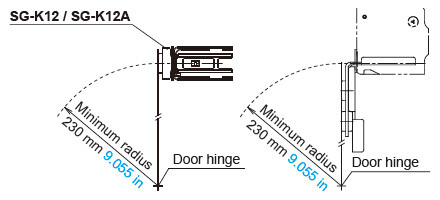
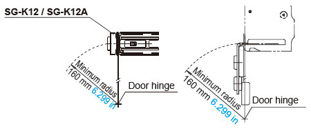
Minimum radius of hinged door
When using the safety switch on hinged doors, refer to the minimum radius of doors shown below. When using on doors with small minimum radius, use the angle adjustable actuator (SG-K13 / SG-K14).
Note : The values indicated in the figures below assume that there is no mechanical interference between the actuator and the safety switch when the door is opened or closed. Because deviation or dislocation of hinged doors may occur in actual applications, make sure of the correct operation before installation.
When using the right-angle actuator (SG-K12 / SG-K12A)
<When the door hinge is on the extension line of the actuator mounting surface>
<When the door hinge is on the extension line of the safety switch surface>
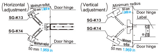
When using the (SG-K13 / SG-K14) angle adjustable (vertical / horizontal) actuator
- When the door hinge is on the extension line of the actuator mounting surface: 70 mm 2.756 in
- When the door hinge is on the extension line of the safety switch surface: 50 mm 1.969 in
<When the door hinge is on the extension line of the actuator mounting surface>
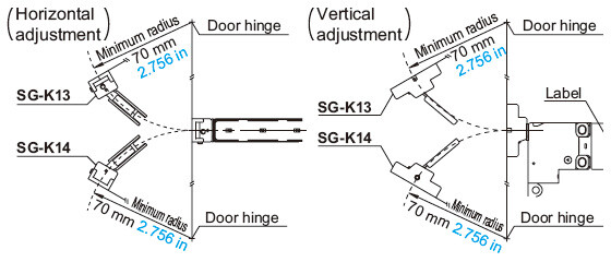
<When the door hinge is on the extension line of the safety switch surface>
Actuator angle adjustment (vertical / horizontal)
- Using the angle adjustment screw (M3 hexagon-socket-head screw), the actuator angle can be adjusted.
Adjustable angle: 0 to 20° - The larger the adjusted angle of the actuator, the smaller the applicable radius of the door opening. After installing the actuator, open the door. Then adjust the actuator so that its edge can be inserted properly into the actuator entry slot of the safety switch.
- After adjusting the actuator angle, apply Loctite to the adjustment screw so that the screw will not move.
Mounting
- Mount the safety switch on a fixed piece of machinery or guard and the actuator on a hinged door. Avoid mounting both the safety switch and actuator on a hinged door. Doing so may cause equipment failure. For more information about how to mount the devices, see the following diagram:
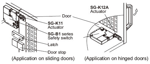
Note: When mounting the actuator, make sure that the actuator enters the slot in the correct direction, as shown on the right figure.
Recommended tightening torque for mounting screws
Safety switch: 1.0 to 1.5 N·m (Three M4 screws)*
Actuator: 1.0 to 1.5 N·m (Two M4 screws)*
* The above recommended tightening torques of the mounting screws are the values confirmed with hexagon-socket-head bolts.
When other screws are used and tightened to a smaller torque, make sure that the screws do not become loose after mounting.
- Mounting bolts must be provided by the users.
- To avoid unauthorized or unintended removal of the safety switch and the actuator, it is recommended that the safety switch and actuator are installed in a secure manner, for example using special screws or welding the screws.
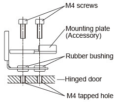
- When installing the SG-K12A actuator, use the mounting plate (supplied with the actuator) on the hinged door, and mount tightly using two M4 screws.
The mounting plate has orientation.
Do not lose the mounting plate.
Adequate performance cannot be obtained without the plate as the actuator may fall off the door.
Cables
- Do not fasten or loosen the gland at the bottom of the safety switch.
- When bending the cable during wiring, make sure that the cable radius is kept at 30 mm 1.181 in minimum.
- When wiring, make sure that water or oil does not enter the cable.
- The solenoid has polarity. Make sure of the correct polarity when wiring.