Ultra-slim Safety Light Curtain Type 4 PLe SIL3 SF4C
Download
-
Basic Information
-
Order guide
-
Option
-
Specifications
-
Dimensions
-
Circuit/ Wiring
-
Cautions For Use
Basic Information

Machine safeguarding without sacrificing productivity
- *1 : The control category differs depending on the configuration and wiring of the external circuit.
Contact Us
- NEWApril 2025 : The order part number and some specifications have changed.
Features
■For your safety
In using the light curtain, please establish a control system to satisfy the below items in order to ensure safety with a total system.
>>Precautions for use
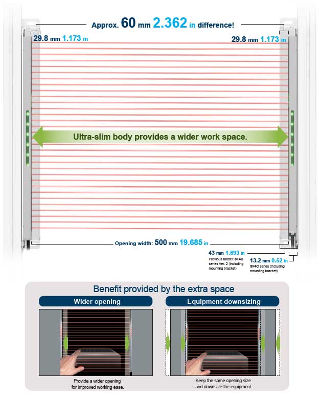
Contributes to Space-saving
The ultra-slim size of the safety light curtain allows maximum use of machine opening to help improve productivity.
Finger protection type (SF4C-F□) offering shorter safety distance
The safety distance of SF4C series finger protection type is 84 mm 3.307 in shorter than that of SF4C series hand protection type (SF4C-H□). As a result, the depth and guard of the equipment can be downsized.
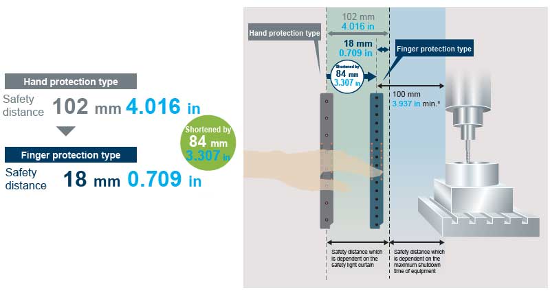
* Calculation based on ISO 13855 with 41 ms or longer being the machinery's maximum stopping time.
* The safety light curtain cannot be installed within a distance of 100 mm 3.937 in. (ISO 13855)
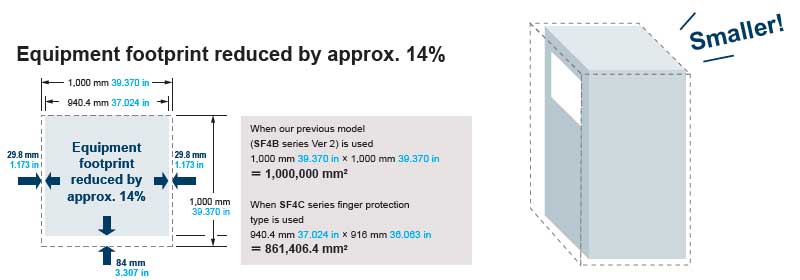
The finger protection type enables downsizing of equipment!
Example: Equipment measuring 1,000 mm 39.370 in in width, 1,000 mm 39.370 in in depth, and 1,800 mm 70.866 in in height
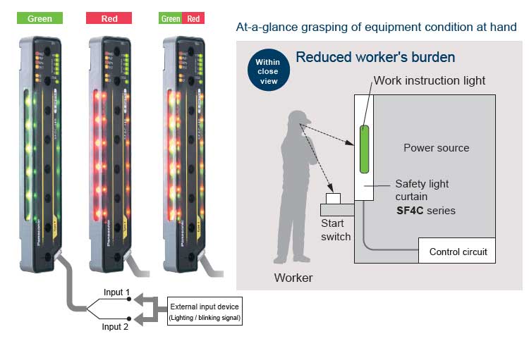
Easy-to-see, useful large multi-purpose indicators
Can also be used as operation indicators,error indicators and muting lamps
The bright LED indicators located in the center of both sides of each safety light curtain can be illuminated by using external inputs. There is no need for setting up a separate work instruction light, so that equipment is consolidated.
* The lighting conditions of SF4C series can be changed by using a handy-controller SFC-HC (optional). It is possible to actuate the lighting together with internal operation, regardless of connection of the large multi-purpose indicator input wires.
Beam-axis alignment indicators help to reduce startup time
Since the beam channels of the safety light curtain are divided into four blocks for the indication of incident light conditions, the beam axes can be aligned intuitively. When the bottommost (or topmost) beam axis is aligned, the LED blinks red. Then, each block lights red as the beam axes become aligned successively. When all channel beam axes are aligned, all LEDs light green. The display also has an incident light intensity indicator (STB) added so that the setup can be carried out with greater stability.

Response time is unified for all beam channels.
All models offer fast response time.
The response time is unified in all models. The response time is remains the same even in models with many beam channels. Even if the number of beam channels is changed, the safety distance, which is dependent on the safety light curtain, stays the same. This eliminates the need for recalculation.

* When a safety sensor (such as a safety light curtain) is connected to the safety input of the SF4C series, the response time will be the total time of the response times of the connected units.
Quick and easy installation
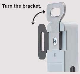
Standard mounting brackets(preinstalled at factory)
Standard mounting brackets are preinstalled at the factory, so the SF4C can be installed right out of the box. Simply turning the mounting bracket ensures secure installation of the upper and lower units.
Wire-saving Y-shaped connector (optional)
By using the Y-shaped connector, the emitter-side cable and receiver-side cable can be consolidated into one cable. This reduces cumbersome wiring work to half.

Lightweight!
The SF4C series is made of resin that is approx. 45 % lighter than the conventional aluminum case type.
Its lightweight body eases the burden on the mounting surface of the equipment and contributes to overall reduced weight during equipment transportation or overseas shipment.
* Except the cable part
IP67 protection structure
Our proprietary laser welding method has achieved an IP67 (IEC) rating with an ultra-slim resin body.
Mutual interference is reduced without needing for interference prevention lines
The ELCA (Extraneous Light Check & Avoid) function automatically shifts the scan timing in order to avoid interference.
Reducing the number of malfunctions caused by extraneous light
Double scanning method and retry processing are effective in eliminating the effects of extraneous light.
Order guide
Product configuration

[1]. [2]. Safety light curtains
Finger protection type
Min. sensing object φ14 mm φ0.551 in(10 mm 0.394 in beam pitch)
| Appearance | Operating range (Note 1) | Model No. (Note 2) <Part No.> | Number of beam channels | Protective height (mm in) | |
|---|---|---|---|---|---|
| [1]Pigtailed type | [2]Cable type | ||||
| 0.1 to 3 m 0.328 to 9.843 ft | SF4C-F15-J05 <USF4C3F151> | SF4C-F15 <USF4C3F150> | 15 | 160 mm 6.299 in |
| SF4C-F23-J05 <USF4C3F231> | SF4C-F23 <USF4C3F230> | 23 | 240 mm 9.449 in | ||
| SF4C-F31-J05 <USF4C3F311> | SF4C-F31 <USF4C3F310> | 31 | 320 mm 12.598 in | ||
| SF4C-F39-J05 <USF4C3F391> | SF4C-F39 <USF4C3F390> | 39 | 400 mm 15.748 in | ||
| SF4C-F47-J05 <USF4C3F471> | SF4C-F47 <USF4C3F470> | 47 | 480 mm 18.898 in | ||
| SF4C-F55-J05 <USF4C3F551> | SF4C-F55 <USF4C3F550> | 55 | 560 mm 22.047 in | ||
| SF4C-F63-J05 <USF4C3F631> | SF4C-F63 <USF4C3F630> | 63 | 640 mm 25.197 in | ||
Hand protection type
Min. sensing object φ25 mm φ0.984 in(20 mm 0.787 in beam pitch)
| Appearance | Operating range (Note 1) | Model No. (Note 2) <Part No.> | Number of beam channels | Protective height (mm in) | |
|---|---|---|---|---|---|
| [1]Pigtailed type | [2]Cable type | ||||
| 0.1 to 3 m 0.328 to 9.843 ft | SF4C-H8-J05 <USF4C3H081> | SF4C-H8 <USF4C3H080> | 8 | 160 mm 6.299 in |
| SF4C-H12-J05 <USF4C3H121> | SF4C-H12 <USF4C3H120> | 12 | 240 mm 9.449 in | ||
| SF4C-H16-J05 <USF4C3H161> | SF4C-H16 <USF4C3H160> | 16 | 320 mm 12.598 in | ||
| SF4C-H20-J05 <USF4C3H201> | SF4C-H20 <USF4C3H200> | 20 | 400 mm 15.748 in | ||
| SF4C-H24-J05 <USF4C3H241> | SF4C-H24 <USF4C3H240> | 24 | 480 mm 18.898 in | ||
| SF4C-H28-J05 <USF4C3H281> | SF4C-H28 <USF4C3H280> | 28 | 560 mm 22.047 in | ||
| SF4C-H32-J05 <USF4C3H321> | SF4C-H32 <USF4C3H320> | 32 | 640 mm 25.197 in | ||
Note: 1) The operating range is the possible setting distance between the emitter and the receiver.
Note: 2) This product is Ver. 3.0. Do not use this product in combination with an emitter or receiver with Ver. 2.1 or earlier. When replacing products, be sure to replace the emitter and receiver as a set.
Note: 3) Do not use the product with Ver. 3.0 in combination with an emitter or receiver with Ver. 2.1 or earlier. When replacing products, be sure to replace the emitter and receiver as a set.
[3]. Mating cables (With connector on one end)
| Appearance | Model No. | Description | |
|---|---|---|---|
| SFB-CC3-MU | Length: 3 m 9.843 ft Net weight: 430 g approx. (2 cables) | Cable with connector on one end for pigtailed type Two cables per set for emitter and receiver Cable color: Gray (for emitter), Gray with black line (for receiver) Connector color: Gray (for emitter), Black (for receiver) The min. bending radius: R6 mm R0.236 in |
| SFB-CC7-MU | Length: 7 m 22.966 ft Net weight: 1,000 g approx. (2 cables) | ||
| SFB-CC10-MU | Length: 10 m 32.808 ft Net weight: 1,300 g approx. (2 cables) | ||
[4]. Mating cables (With connectors on both ends)
| Type | Appearance | Model No. | Description | |
|---|---|---|---|---|
| For emitter |
| SFB-CCJ3E-MU | Length: 3 m 9.843 ft Net weight: 190 g approx. (1 cables) | Cable with connectors on both ends for pigtailed type Cable color: Gray (for emitter), Gray with black line (for receiver) Connector color: Gray (for emitter), Black (for receiver) The min. bending radius: R6 mm R0.236 in |
| SFB-CCJ10E-MU | Length: 10 m 32.808 ft Net weight: 660 g approx. (1 cables) | |||
| For receiver | SFB-CCJ3D-MU | Length: 3 m 9.843 ft Net weight: 210 g approx. (1 cables) | ||
| SFB-CCJ10D-MU | Length: 10 m 32.808 ft Net weight: 680 g approx. (1 cables) | |||
Spare parts (Accessories for safety light curtain)
| Designation | Model No. | Description |
|---|---|---|
| Standard mounting bracket | MS-SFC-1 | Allows the safety light curtain to be mounted at the rear with one M5 hexagon-socket-head bolt. Mounting direction of the bracket can be selected between vertical or horizontal (no dead zone). (4 pcs. per set for emitter and receiver) (Note) |
| Test rod φ14 | SF4C-TR14 | Min. sensing object for regular checking (φ14 mm φ0.551 in) |
| Test rod φ25 | SF4C-TR25 | Min. sensing object for regular checking (φ25 mm φ0.984 in) |
Note :
The body of the safety light curtain is made of resin, so please take into account the expansion and contraction of the longitudinal dimension.
When machining mounting holes, please check the actual product.
Standard mounting bracket
MS-SFC-1

<Mountable in three directions>

Option
Mounting bracket
| Designation | Model No. | Description |
|---|---|---|
| NA2-N compatible mounting bracket | MS-SFC-2 | Used when changing over area sensor NA2-N series to the SF4C series. The mounting holes of NA2-N series can continue to be used. Center mounting by a M6 hexagon-socket-head bolt is also possible. (4 pcs. per set for emitter and receiver) (Note) |
| Versatile bracket | MS-SFC-3 | Two ways of mounting are possible. (1) Rear mounting which enables beam adjustment (2) Dead zoneless center mounting on aluminum frame (4 pcs. per set for emitter and receiver) (Note) |
| Intermediate supporting bracket for versatile bracket | MS-SFC-4 | Used to support the safety light curtain in the middle. Be sure to purchase it when using the versatile bracket MS-SFC-3(optional) on SF4C-F55(-J05),SF4C-F63(-J05), SF4C-H28(-J05) or SF4C-H32(-J05). (2 pcs. per set for emitter and receiver) (Note) |
Note :
The body of the safety light curtain is made of resin, so please take into account the expansion and contraction of the longitudinal dimension.
When machining mounting holes, please check the actual product.
NA2-N compatible mounting bracket
MS-SFC-2

Versatile bracket
MS-SFC-3
<Rear mounting>

<Dead zoneless mounting>

Intermediate supporting bracket for versatile bracket
MS-SFC-4

Control unit
| Designation | Appearance | Model No. | Description |
|---|---|---|---|
| Slim type control unit |
| SF-C13 | Use a discrete wire cable to connect to the safety light curtain. Relay output. Compatible with up to Control Category 4. |
Recommended safety relay
SF relay, slim type
SF series
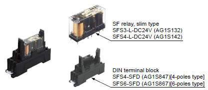
Note:Please contactour sales officefor details on the recommended products.
| Type | With LED indicator | |
|---|---|---|
| Model No. | SFS3-L-DC24V | SFS4-L-DC24V |
| Part No. | AG1S132 | AG1S142 |
| Contact arrangement | 3a1b | 4a2b |
| Rated nominal switching capacity | 6A/250V AC、6A/30V DC | |
| Min. switching capacity | 1mA/5V DC | |
| Coil rating | 15mA/24V DC | 20.8mA/24V DC |
| Rated power consumption | 360mW | 500mW |
| Operation time | 20ms or less | |
| Release time | 20ms or less | |
| Ambient temperature | -40 to +85 ℃ -40 to + 185 ℉ (Humidity: 5 to 85 % RH) | |
| Applicable certifications | UL/c-UL, TÜV, Korea S-mark | |
Y-shaped connector
| Type | Appearance | Model No. | Description | |
|---|---|---|---|---|
| Wire-saving Y-shaped connector |
| SFC-WY1 | Wire-saving connector for SF4C-F□-J05 and SF4C-H□-J05. Cables of emitter and receiver are consolidated into one cable for wire-saving. Wiring has +24 V, 0 V, OSSD 1, OSSD 2, output polarity setting wire (shield), large multi-purpose indicator input 1, and large multi-purpose indicator input 2 only. Net weight: 40 g approx. Power wire and synchronization wire are connected inside the connector. Interlock is disabled (automatic reset). | |
| Cable with connector on one side |
| WY1-CCN3 | Cable length: 3 m 9.843 ft Net weight: 200 g approx. (1 cable) | Mating cable for Y-shaped connector Cable color: Gray (with black line) Connector color: Black The min. bending radius: R6 mm R0.236 in Connector outer diameter: ø14 mm ø0.551 in max. |
| WY1-CCN10 | Cable length: 10 m 32.808 ft Net weight: 620 g approx. (1 cable) | |||
By using the Y-shaped connector, the least required wires such as power or safety output are consolidated into one cable. Man-hours taken for wiring is eliminated to the minimum. Construction times as well as wiring mistakes are greatly reduced.


Wiring diagram of control unit SF-C13
<For PNP output (minus ground)>
• Connect the safety light curtain control outputs OSSD 1 and OSSD 2 to S1 and S2 respectively.

Notes:
1) The above diagram is when using manual reset. If automatic reset is used, disconnect the lead from X2 and connect it to X3. In this case, a reset (RESET) button is not needed.
2) Use a momentary-type switch as the reset (RESET) button.3) Unused wires must be insulated.
<For NPN output (plus ground)>
• Connect the safety light curtain control outputs OSSD 1 and OSSD 2 to S4 and S2 respectively and ground the + side.

Notes:
1) The above diagram is when using manual reset. If automatic reset is used, disconnect the lead from X2 and connect it to X3. In this case, a reset (RESET) button is not needed.
2) Use a momentary-type switch as the reset (RESET) button.3) Unused wires must be insulated.
Handy-controller

Metal protection case
| Applicable beam channels | Metal protection case (2 pcs. per set for emitter and receiver) | |
|---|---|---|
| SF4C-H□ | SF4C-F□ | Model No. |
| 8 | 15 | MS-SFCH-8 |
| 12 | 23 | MS-SFCH-12 |
| 16 | 31 | MS-SFCH-16 |
| 20 | 39 | MS-SFCH-20 |
| 24 | 47 | MS-SFCH-24 |
| 28 | 55 | MS-SFCH-28 |
| 32 | 63 | MS-SFCH-32 |
MC-SFCH-□

MS-SFCH-8

Specifications
Safety light curtain individual specifications
SF4C-F□
| Type | Min. sensing object ø14 mm ø0.551 in type (10 mm 0.394 in beam pitch) | |||
|---|---|---|---|---|
| Model No. | Pigtailed type | SF4C-F15-J05 | SF4C-F23-J05 | SF4C-F31-J05 |
| Cable type | SF4C-F15 | SF4C-F23 | SF4C-F31 | |
| No. of beam channels | 15 | 23 | 31 | |
| Protective height | 160 mm 6.299 in | 240 mm 9.449 in | 320 mm 12.598 in | |
| Current consumption | Large multipurpose indicator lights off | Emitter: 70 mA or less Receiver: 80 mA or less | Emitter: 75 mA or less Receiver: 85 mA or less | |
| Large multipurpose indicator lights up | Emitter: 105 mA or less Receiver: 110 mA or less | Emitter: 110 mA or less Receiver: 115 mA or less | ||
| PFH | 1.21 x 10⁻⁹ | 1.65 x 10⁻⁹ | 2.09 x 10⁻⁹ | |
| MTTFD | 345 years | 305 years | 273 years | |
| Net weight (Total of emitter and receiver) | Pigtailed type | 210 g approx. | 270 g approx. | 340 g approx. |
| Cable type | 600 g approx. | 670 g approx. | 730 g approx. | |
| Type | Min. sensing object ø14 mm ø0.551 in type (10 mm 0.394 in beam pitch) | ||||
|---|---|---|---|---|---|
| Model No. | Pigtailed type | SF4C-F39 -J05 | SF4C-F47 -J05 | SF4C-F55 -J05 | SF4C-F63 -J05 |
| Cable type | SF4C-F39 | SF4C-F47 | SF4C-F55 | SF4C-F63 | |
| No. of beam channels | 39 | 47 | 55 | 63 | |
| Protective height | 400 mm 15.748 in | 480 mm 18.898 in | 560 mm 22.047 in | 640 mm 25.197 in | |
| Current consumption | Large multipurpose indicator lights off | Emitter: 80 mA or less Receiver: 90 mA or less | Emitter: 85 mA or less Receiver: 95 mA or less | ||
| Large multipurpose indicator lights up | Emitter: 115 mA or less Receiver: 120 mA or less | Emitter: 120 mA or less Receiver: 125 mA or less | |||
| PFH | 2.54x 10⁻⁹ | 2.98 x 10⁻⁹ | 3.42 x 10⁻⁹ | 3.86 x 10⁻⁹ | |
| MTTFD | 246 years | 225 years | 207 years | 192 years | |
| Net weight (Total of emitter and receiver) | Pigtailed type | 400 g approx. | 470 g approx. | 540 g approx. | 600 g approx. |
| Cable type | 800 g approx. | 860 g approx. | 930 g approx. | 1,000 g approx. | |
SF4C-H□
| Type | Min. sensing object ø25 mm ø0.984 in type (20 mm 0.787 in beam pitch) | |||
|---|---|---|---|---|
| Model No. | Pigtailed type | SF4C-H8-J05 | SF4C-H12-J05 | SF4C-H16-J05 |
| Cable type | SF4C-H8 | SF4C-H12 | SF4C-H16 | |
| No. of beam channels | 8 | 12 | 16 | |
| Protective height | 160 mm 6.299 in | 240 mm 9.449 in | 320 mm 12.598 in | |
| Current consumption | Large multipurpose indicator lights off | Emitter: 70 mA or less Receiver: 85 mA or less | Emitter: 70 mA or less Receiver: 90 mA or less | |
| Large multipurpose indicator lights up | Emitter: 120 mA or less Receiver: 135 mA or less | Emitter: 120 mA or less Receiver: 140 mA or less | ||
| PFH | 8.26 x 10⁻¹⁰ | 1.07 x 10⁻⁹ | 1.27 x 10⁻⁹ | |
| MTTFD | 391 years | 360 years | 339 years | |
| Net weight (Total of emitter and receiver) | Pigtailed type | 220 g approx. | 360 g approx. | 340 g approx. |
| Cable type | 610 g approx. | 680 g approx. | 740 g approx. | |
| Type | Min. sensing object ø25 mm ø0.984 in type (20 mm 0.787 in beam pitch) | ||||
|---|---|---|---|---|---|
| Model No. | Pigtailed type | SF4C-H20 -J05 | SF4C-H24 -J05 | SF4C-H28 -J05 | SF4C-H32 -J05 |
| Cable type | SF4C-H20 | SF4C-H24 | SF4C-H28 | SF4C-H32 | |
| No. of beam channels | 20 | 24 | 28 | 32 | |
| Protective height | 400 mm 15.748 in | 480 mm 18.898 in | 560 mm 22.047 in | 640 mm 25.197 in | |
| Current consumption | Large multipurpose indicator lights off | Emitter: 75 mA or less Receiver: 95 mA or less | Emitter: 80 mA or less Receiver: 100 mA or less | ||
| Large multipurpose indicator lights up | Emitter: 120 mA or less Receiver: 145 mA or less | Emitter: 120 mA or less Receiver: 150 mA or less | |||
| PFH | 1.52 x 10⁻⁹ | 1.72 x 10⁻⁹ | 1.97 x 10⁻⁹ | 2.22 x 10⁻⁹ | |
| MTTFD | 316 years | 299 years | 281 years | 265 years | |
| Net weight (Total of emitter and receiver) | Pigtailed type | 400 g approx. | 460 g approx. | 530 g approx. | 600 g approx. |
| Cable type | 800 g approx. | 850 g approx. | 930 g approx. | 990 g approx. | |
Note: Where measurement conditions have not been specified precisely, the conditions used were an ambient temperature of +20 ℃ +68 ℉. PFH: Probability of dangerous failure per hour, MTTFD: Mean time to dangerous failure (in years)
Safety light curtain common specifications
| Type | Pigtailed type | Cable type | |||
|---|---|---|---|---|---|
| Model No. | SF4C-F□-J05 | SF4C-H□-J05 | SF4C-F□ | SF4C-H□ | |
| Applicable standards | International standard | IEC 61496-1/2 (Type 4), ISO 13849-1(Category 4, PLe), IEC 61508-1 to 3 (SIL 3) | |||
| Japan | JIS B 9704-1/2 (Type 4), JIS B 9705-1 (Category 4), JIS C 0508-1 to 3(SIL3) | ||||
| Europe (Note 2) | EN 61496-1 (Type 4), EN ISO 13849-1(Category 4, PLe), EN 61508-1 to 3 (SIL 3), EN 55011, EN 50178, EN 61000-6-2 | ||||
| North America (Note 3) | ANSI/UL 61496-1/2 (Type 4), ANSI/UL 508, UL 1998 (Class 2), CAN/CSA 61496-1/2 (Type 4), CAN/CSA C22.2 No.14,OSHA 1910.212, OSHA 1910.217(C), ANSI B11.1 to B11.19, ANSI/RIA 15.06 | ||||
| Applicable regulations and certifications | CE Marking (Machinery Directive, EMC Directive, RoHS Directive), UKCA Marking [Supply of Machinery (Safety) Regulations, EMC Regulations, RoHS Regulations], TÜV SÜD certification(U.S.A., Canada), Korea KCs mark (Note 4) | ||||
| Operating range (Note 5) | 0.1 to 3 m 0.328 to 9.843 ft | ||||
| Beam pitch | 10 mm 0.394 in | 20 mm 0.787 in | 10 mm 0.394 in | 20 mm 0.787 in | |
| Min. sensing object (Note 6) | ø14 mm ø0.551 in opaque object | ø25 mm ø0.984 in opaque object | ø14 mm ø0.551 in opaque object | ø25 mm ø0.984 in opaque object | |
| Effective aperture angle | ±2.5°or less [for an operating range exceeding 3 m 9.843 ft (conforming to IEC 61496-2 / ANSI/UL 61496-2)] | ||||
| Supply voltage | 24 V DC +10-15 % Ripple P-P 10 % or less | ||||
| Control outputs (OSSD 1, OSSD 2)(Note 12) | PNP open-collector transistor / NPN open-collector transistor (switching method) (Note 4) <When selecting PNP output> ・Max. source current: 200 mA ・Applied voltage: same as supply voltage (between the control output and +V) ・Residual voltage: 2.5 V or less (source current 200 mA, when using 10 m 32.808 ft length cable) ・Leakage current: 200 μA or less (including power supply OFF condition) ・Max. load capacity: 1 μF (No load to Max. source current) ・Load wiring resistance: 3 Ω or less <When selecting NPN output> ・Max. sink current: 200 mA ・Applied voltage: same as supply voltage (between the control output and 0 V) ・Residual voltage: 2.5 V or less (sink current 200 mA, when using 10 m 32.808 ft length cable) ・Leakage current: 200 μA or less (including power supply OFF condition) ・Max. load capacity: 1 μF (No load to Max. sink current) ・Load wiring resistance: 3 Ω or less | ||||
| Operation mode | ON when all beam channels are received, OFF when one or more beam channels are interrupted (OFF also in case of any malfunction in the safety light curtain or the synchronization signal)(Note 7,8) | ||||
| Protection circuit | Incorporated | ||||
| Response time | OFF response: 9 ms or less, ON response: 90 ms or less | OFF response: 7 ms or less, ON response: 90 ms or less | OFF response: 9 ms or less, ON response: 90 ms or less | OFF response: 7 ms or less, ON response: 90 ms or less | |
| Auxiliary output (Non-safety output) | PNP open-collector transistor / NPN open-collector transistor (switching method) (Note 4) <When selecting PNP output> ・Max. source current: 100 mA ・Applied voltage: same as supply voltage (between the auxiliary source and +V) ・Residual voltage: 2.5 V or less (source current 100 mA, when using 10 m 32.808 ft length cable) <When selecting NPN output> ・Max. sink current: 100 mA ・Applied voltage: same as supply voltage (between the auxiliary sink and 0 V) ・Residual voltage: 2.5 V or less (sink current 100 mA, when using 10 m 32.808 ft length cable) | ||||
| Operation mode | OFF when control outputs are ON, ON when control outputs are OFF [Factory setting, operating mode can be changed using the handy-controller SFC-HC(optional).] | ||||
| Protection circuit | Incorporated | ||||
| function | ELCA function (reducing mutual interference automatically), test input function, Interlock function [manual reset / automatic reset (Note 9)], external device monitor function, safety input function (safety contact), muting function, override function, large multi-purpose indicator function | ||||
| Optional functions (Note 10) | Fixed blanking, floating blanking, auxiliary output change, safety input (safety sensor), large multi-purpose indicator setting change, interlock setting change, external relay monitor setting change, muting setting change, override setting change, protecting | ||||
| Pollution degree / Operating altitude | 3 / 2,000 m 6,561 68 ft or less (Note 11) | ||||
| Degree of protection | IP67 / IP65 (IEC) | ||||
| Ambient temperature | -10 to +55 ℃ +14 to +131 ℉ (No dew condensation or icing allowed)(Note 12), Storage: -25 to +60 ℃ -13 to +140 ℉ | ||||
| Ambient humidity | 30 to 85 % RH, Storage: 30 to 85 % RH | ||||
| Ambient illuminance | Incandescent light: 5,000 lx or less at the light-receiving face | ||||
| Dielectric strength voltage | 1,000 V AC for one min. between all supply terminals connected together and enclosure | ||||
| Insulation resistance | 20 MΩ, or more, with 500 V DC megger between all supply terminals connected together and enclosure | ||||
| Vibration resistance | 10 to 55 Hz frequency, 0.75 mm 0.030 in double amplitude in X, Y and Z directions for two hours each | ||||
| Shock resistance | 300 m/s2 acceleration (30 G approx.) in X, Y and Z directions three times each | ||||
| Emitting element | Infrared LED (Peak emission wavelength: 855 nm 0.034 mil) | ||||
| Material | Enclosure: Polycarbonate alloy, Sensing surface: Polycarbonate alloy, MS-SFC-1 (Standard mounting bracket): SUS | ||||
| Cable | 0.15 mm2 12-core heat-resistant PVC cable with connector, 0.5 m 1.640 ft long | 0.15 mm2 12-core heat-resistant PVC cable, 5 m 16.404 ft long | |||
| Cable extension (Note 13, 14) | Extension up to 30 m 98.425 ft is possible for both emitter and receiver optional mating cables | Extension up to 30 m 98.425 ft is possible for both emitter and receiver, with 0.2 mm2 or more cable | |||
| Accessories | MS-SFC-1 (Standard mounting bracket): 1 set,SF4C-TR14 (Test rod): 1 No. | MS-SFC-1 (Standard mounting bracket): 1 set,SF4C-TR25 (Test rod): 1 No. | MS-SFC-1 (Standard mounting bracket): 1 set,SF4C-TR14 (Test rod): 1 No. | MS-SFC-1 (Standard mounting bracket): 1 set,SF4C-TR25 (Test rod): 1 No. | |
Notes:
1) Where measurement conditions have not been specified precisely, the conditions used were an ambient temperature of +20 ℃ +68 ℉.
2) Regarding EU Machinery Directive, a Notified Body, TUV SUD, has certified with the type examination certificate.
3) With regards to the standards in the US/Canada, a Notified Body, TÜV SÜD, has certified the CTÜVUS mark.
4) When using this device in Korea with KCs mark, be sure to ground to 0V side (PNP output).
5) The operating range is the possible setting distance between the emitter and the receiver.
6) When the floating blanking function is used, the size of the min. sensing object is changed. Please refer to the instruction manual for details.
7) The outputs are not “OFF” when muting function is active even if the beam channel is interruped.
8) In case the blanking function is valid, the operation mode is changed.
9) The manual reset and automatic reset are possible to be switched depending on the wiring status.
10) In case of using optional function, the handy-controller SFC-HC (optional) is required.
11) Do not use or store in an environment pressurized to atmospheric pressure or higher at an altitude of 0 m.
12) When large multi-purpose indicator is used, allowable upper-limit ambient temperature is +50 °C +122 °F and control output (OSSD 1/2) must not exceed 100 mA.
13) When extending the cables of emitter and receiver, make sure total measured length of all cables (main unit cables and connection cables) is no more than 30 m 98.425 ft.
14) When the synchronization + wire (orange) and synchronization - wire (orange / black) is extended with a cable other than exclusive cable, use a 0.2 mm2 or more shielded twisted pair cable.
Handy-controller
| Model No. | SFC-HC |
|---|---|
| Supply voltage | 24 V DC +10-15 % Ripple P-P 10 % or less (common to safety light curtain power supply) |
| Current consumption | 65 mA or less |
| Communication method | RS-485 two-way communications (Specific procedure) |
| Digital display | 4-digit red LED display x 2 (Selected beam channels, setting contents etc. are displayed.) |
| Function indicators | Green LED x 9 (Set function is displayed.) |
| Functions | Fixed blanking / Floating blanking / Auxiliary output change / Satety input setting change / Large multi-purpose indicator setting change / Muting setting change / Interlock setting change / External device monitoring setting change / Override setting changing function 60 sec. / Protecting |
| Ambient temperature | -10 to +55 ℃ +14 to +131 ℉ (No dew condensation or icing allowed), Storage: -25 to +70 ℃ -13 to +158 ℉ |
| Ambient humidity | 30 to 85 % RH, Storage: 30 to 85 % RH |
| Voltage withstandability | 1,000 V AC for one min. between all supply terminals connected together and enclosure |
| Insulation resistance | 20 MΩ, or more, with 500 V DC megger between all supply terminals connected together and enclosure |
| Cable | 12-core shielded cable, 0.5 m 1.640 ft long, with a connector at the end (2 cables) |
| Weight | Net weight: 200 g approx. |
Note: Where measurement conditions have not been specified precisely, the conditions used were an ambient temperature of +20 ℃ +68 ℉.
Dimensions
- Unit: mm in
SF4C-F□
SF4C-H□
Safety Light curtain
Mounting bracket assembly dimensions
Mounting drawing for the safety light curtains using the standard mounting brackets MS-SFC-1 (accessory).
<Center mounting>

<Dead zoneless mounting>

Note: In case of SF4C-F15(-J05) and SF4C-H8(-J05) are not provided with digital error indicator (red).
Connector of the pigtailed type SF4C-F□-J05 / SF4C-H□-J05

| Model No. | A | B | C | D | E | |
|---|---|---|---|---|---|---|
| SF4C-F15(-J05) | SF4C-H8(-J05) | 140 5.512 | 160 6.299 | 172 6.772 | 184 7.244 | 130 5.118 |
| SF4C-F23(-J05) | SF4C-H12(-J05) | 220 8.661 | 240 9.449 | 252 9.921 | 264 10.394 | 210 8.268 |
| SF4C-F31(-J05) | SF4C-H16(-J05) | 300 11.811 | 320 12.598 | 332 13.071 | 344 13.543 | 290 11.417 |
| SF4C-F39(-J05) | SF4C-H20(-J05) | 380 14.961 | 400 15.748 | 412 16.220 | 424 16.693 | 370 14.567 |
| SF4C-F47(-J05) | SF4C-H24(-J05) | 460 18.110 | 480 18.898 | 492 19.370 | 504 19.842 | 450 17.717 |
| SF4C-F55(-J05) | SF4C-H28(-J05) | 540 21.260 | 560 22.047 | 572 22.520 | 584 22.992 | 530 20.866 |
| SF4C-F63(-J05) | SF4C-H32(-J05) | 620 24.409 | 640 25.197 | 652 25.669 | 664 26.142 | 610 24.016 |
| Model No. | F | G |
|---|---|---|
| SF4C-F□(-J05) | 10 0.394 | ø5 ø0.197 |
| SF4C-H□(-J05) | 20 0.787 |
Notes:
2) The body of the safety light curtain is made of resin, so please take into account the expansion and contraction of the longitudinal dimension.
When machining mounting holes, please check the actual product.
SF4C-F□
SF4C-H□
Mounting drawing for the safety light curtains using the versatile brackets MS-SFC-C3 (optional) and intermediate supporting bracket for versatile brackets MS-SFC-F4 (optional).
<Rear mounting>

<Dead zoneless mounting>

| Model No. | Inter mediate supporting bracket | A | A' | B | B' | C | D | |
|---|---|---|---|---|---|---|---|---|
| SF4C-F15(-J05) | SF4C-H8(-J05) | - | 175 6.890 | 116 4.567 | - | - | 190 7.480 | 160 6.299 |
| SF4C-F23(-J05) | SF4C-H12(-J05) | - | 255 10.039 | 196 7.717 | - | - | 270 10.630 | 240 9.449 |
| SF4C-F31(-J05) | SF4C-H16(-J05) | - | 335 13.189 | 276 10.866 | - | - | 350 13.780 | 320 12.598 |
| SF4C-F39(-J05) | SF4C-H20(-J05) | - | 415 16.339 | 356 14.016 | - | - | 430 16.929 | 400 15.748 |
| SF4C-F47(-J05) | SF4C-H24(-J05) | - | 495 19.488 | 436 17.165 | - | - | 510 20.079 | 480 18.898 |
| SF4C-F55(-J05) | SF4C-H28(-J05) | ○ | 575 22.638 | 516 20.315 | 238 to 338 9.370 to 13.307 | 209 to 309 8.228 to 12.165 | 590 23.228 | 560 22.047 |
| SF4C-F63(-J05) | SF4C-H32(-J05) | ○ | 655 25.787 | 596 23.465 | 278 to 378 10.945 to 14.882 | 249 to 349 9.803 to 13.740 | 670 26.378 | 640 25.197 |
Note:
1) Be sure to mount MS-SFC-4 when using SF4C-F55(-J05), SF4C-F63(-J05), SF4C-H28(-J05) and SF4C-H32(-J05).
2) The body of the safety light curtain is made of resin, so please take into account the expansion and contraction of the longitudinal dimension.
When machining mounting holes, please check the actual product.
MS-SFC-1
Standard mounting bracket (Accessory)
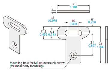
Material: Stainless steel (SUS304)
Net weight: 32 g approx. (4 pcs.)
Gross weight: 35 g appox.
Four bracket set[Four M3 (length 4 mm 0.157 in) countersunk screws are attached.]
MS-SFC-2
NA2-N compatible mounting bracket (Optional)
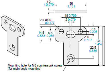
Material: Stainless steel (SUS304)
Net weight: 36 g approx. (4 pcs.)
Gross weight: 40 g appox.
Four bracket set[Four M3 (length 4 mm0.157 in) countersunk screws are attached.]
MS-SFC-3
Versatile bracket (Optional)
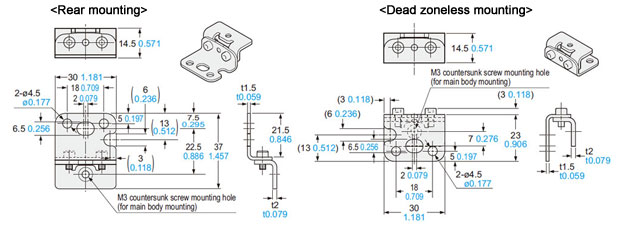
Material: Stainless steel (SUS304)
Net weight: 75 g approx. (4 pcs.)
Gross weight: 90 g appox.
Four bracket set[Four M3 (length 4 mm 0.157 in) countersunk screws are attached.]
MS-SFC-4
Intermediate supporting bracket for versatile bracket (Optional)
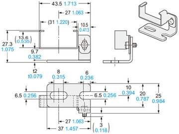
Material: Stainless steel (SUS304)
Net weight: 40 g approx. (2 pcs.)
Gross weight: 60 g appox.
Two bracket set
MS-SFCH-□
Metal protection case (Optional)
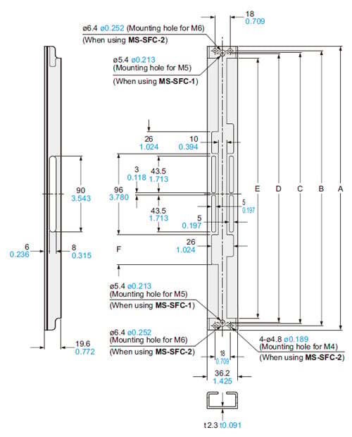
Material: Aluminum
| Model No. | A | B | C | D | E | F | Net weight (2 pcs.) |
|---|---|---|---|---|---|---|---|
| MS-SFCH-8 | 190 7.480 | 180 7.087 | 175 6.890 | 172 6.772 | 162 6.378 | 26 1.024 | 160 g approx. |
| MS-SFCH-12 | 270 10.630 | 260 10.236 | 255 10.039 | 252 9.921 | 242 9.528 | 35 1.378 | 240 g approx. |
| MS-SFCH-16 | 350 13.780 | 340 13.386 | 335 13.189 | 332 13.071 | 322 12.677 | 35 1.378 | 340 g approx. |
| MS-SFCH-20 | 430 16.929 | 420 16.535 | 415 16.339 | 412 16.220 | 402 15.827 | 35 1.378 | 420 g approx. |
| MS-SFCH-24 | 510 20.079 | 500 19.685 | 495 19.488 | 492 19.370 | 482 18.976 | 35 1.378 | 520 g approx. |
| MS-SFCH-28 | 590 23.228 | 580 22.835 | 575 22.638 | 572 22.520 | 562 22.126 | 35 1.378 | 600 g approx. |
| MS-SFCH-32 | 670 26.378 | 660 25.984 | 655 25.787 | 652 25.669 | 642 25.276 | 35 1.378 | 700 g approx. |
Assembly dimensions
Mounting drawing for the safety light curtains using the metal protection case (MS-SFCH-□).
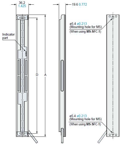
| Model No. | A | D |
|---|---|---|
| MS-SFCH-8 | 190 7.480 | 172 6.772 |
| MS-SFCH-12 | 270 10.630 | 252 9.921 |
| MS-SFCH-16 | 350 13.780 | 332 13.071 |
| MS-SFCH-20 | 430 16.929 | 412 16.220 |
| MS-SFCH-24 | 510 20.079 | 492 19.370 |
| MS-SFCH-28 | 590 23.228 | 572 22.520 |
| MS-SFCH-32 | 670 26.378 | 652 25.669 |
SFB-CC□-MU
Mating cable with connector on one end (Optional)

• Length L
| Model No. | Length L |
|---|---|
| SFB-CC3-MU | 3,000 118.110 |
| SFB-CC7-MU | 7,000 275.590 |
| SFB-CC10-MU | 10,000 393.700 |
SFB-CCJ□-MU
Mating cable with connectors on both ends (Optional)

• Length L
| Model No. | Length L |
|---|---|
| SFB-CCJ3D-MU | 3,000 118.110 |
| SFB-CCJ3E-MU | |
| SFB-CCJ10D-MU | 10,000 393.700 |
| SFB-CCJ10E-MU |
SFC-WY1
Y-shaped connector (Optional)

WY1-CCN3
WY1-CCN10
Mating cable (Optional)

• Length L
| Model No. | Length L |
|---|---|
| WY1-CCN3 | 3,000 118.110 |
| WY1-CCN10 | 10,000 393.700 |
SFC-HC
Handy-controller (Optional)

SF-C13
Control unit (Optional)

I/O Circuit and Wiring diagrams
I/O circuit diagram
<In case of using I/O circuit for PNP output>

・S1, S2
Switch S1
- Test input / Reset input
For manual reset
Vs to Vs – 3.5 V (sink current 5 mA or less): OFF (Note)
Open: ON
For automatic reset
Vs to Vs – 3.5 V (sink current 5 mA or less): ON (Note)
Open: OFF
Switch S2
- Interlock setting input, Override input, Muting input 1 / 2,
Large multi-purpose indicator input 1 / 2,
Vs to Vs – 3.5 V (sink current 5 mA or less): Valid (Note)
Open: Invalid
Note: Vs is the applying supply voltage.
<In case of using I/O circuit for NPN output>

・S1, S2
Switch S1
- Test input / Reset input
For manual reset
0 to +2.5 V (source current 5 mA or less): OFF
Open: ON
For automatic reset
0 to +2.5 V (source current 5 mA or less): OFF
Open: ON
Switch S2
- Interlock setting input, Override input, Muting input 1 / 2,
Large multi-purpose indicator input 1 / 2,
0 to +2.5 V (source current 5 mA or less): Valid
Open: Invalid
Connection example
Basic wiring: Min. operation only
This is the general configuration using one set of the emitter and receiver facing each other. The control outputs (OSSD 1 / OSSD 2) turn OFF if the light is interrupted, while they automatically turn ON if receive the light.
The auxiliary output is used to invalid the external device monitoring function. The auxiliary output cannot be connected to external devices.
<In case of using I/O circuit for PNP output>

| Interlock function | Disabled (Automatic reset) |
|---|---|
| External device monitoring function | Disabled |
| Auxiliary output | Not used |
| Output polarity setting wire | PNP |
| Safety input | Invalid |
<In case of using I/O circuit for NPN output>

| Interlock function | Disabled (Automatic reset) |
|---|---|
| External device monitoring function | Disabled |
| Auxiliary output | Not used |
| Output polarity setting wire | NPN |
| Safety input | Invalid |
Wiring
- Be sure to carry out the wiring in the power supply OFF condition.
- All electrical wiring should conform to the regional electrical regulations and laws. The wiring should be done by engineer(s) having the special electrical knowledge.
- Do not run the wires together with high-voltage lines or power lines or put them in the same raceway. This can cause malfunction due to induction.
- In case of extending the cable of the emitter or the receiver, each can be extended up to 30 m 98.425 ft by using the exclusive cable.
- When the synchronization + wire (orange) and synchronization - wire (orange / black) is extended with a cable other than exclusive cable, use a 0.2 mm2 or more shielded twisted pair cable.
- Do not control the device only at one control output (OSSD 1 / 2).
- In order that the output is not turned ON due to earth fault of the control output (OSSD 1 / 2) wires, be sure to ground to 0 V side (PNP output) / +V side (NPN output).
- When using this device in Korea with KCs mark, be sure to ground to 0 V side (PNP output).
Cautions For Use
- When this device is used in the "PSDI mode", an appropriate control circuit must be configured between this device and the machinery. For details, be sure to refer to the standards or regulations applicable in each region or country.
- This catalog is a guide to select a suitable product. Be sure to read instruction manual prior to its use.
- Both emitter and receiver are adjusted before shipment, please apply both emitter and receiver with the same serial No. The serial No. is indicated on the plates of both emitter and receiver. (Indicated under model No.)
- Make sure to carry out the test run before regular operation.
- Do not install this safety light curtain with a machine whose operation cannot be stopped immediately in the middle of an operation cycle by an emergency stop equipment.
Others
- This device has been developed / produced for industrial use only.
- Do not use this product with mobile equipment such as an automated guided vehicle (AGV).
- Do not use during the initial transient time (2 sec.) after the power supply is switched on.
- Avoid dust, dirt and steam.
- Take care that the sensor does not come in direct contact with water, oil, grease, or organic solvents, such as, thinner, etc.
- Take care that the sensor is not directly exposed to fluorescent lamp from a rapid-starter lamp or a high frequency lighting device, as it may affect the sensing performance.
- The body of the safety light curtain is made of resin, so please take into account the expansion and contraction of the longitudinal dimension.
When machining mounting holes, please check the actual product.
Handy-controller
- This safety light curtain enables to set each function using the handy-controller SFC-HC (optional). Among the functions, the contents related to the safety distance such as the size of the minimum sensing object and response time are varied depending on the setting condition.
When setting each function, re-calculate the safety distance, and make enough space larger than the calculated safety distance. Failure to do so might cause the accident that the device cannot stop quickly before reaching the dangerous area of the machinery, resulting in the serious injury or death.
- Refer to the instruction manual of the handy-controller for details of the function settings for using handycontroller SFC-HC (optional).


