Basic Information
Compact, light weight design, and advanced functionality in one package


CE : Machinery Directive, EMC Directive
UKCA : Machinery Regulations, EMC Regulations
UL, CSA : Certified by TÜV SÜD America Inc.


- *1 : The control category differs depending on the configuration and wiring of the external circuit.
Features
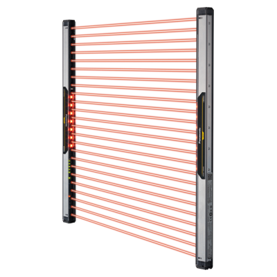
Compact profile design, maximize the machinery opening area
The SF4B-C series is designed to fit onto an aluminum frame, maximizing the machinery opening area. It can even allow zero dead zone.
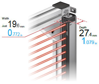

■The safety light curtain is thin, so its bulge from frame can be minimized.
■The safety light curtain protrudes neither into the machinery opening nor outside the frame.* When using standard mounting bracketsMS-SF4BC-1(optional)
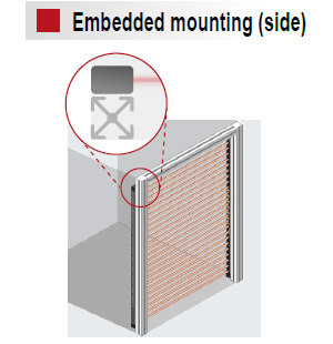
■The safety light curtain fits onto frame perfectly, even in embedded installations.
■The safety light curtain protrudes neither into the machinery opening nor outside the frame.
■The safety light curtain will not be damaged due to collision with workpiece.* When using standard mounting brackets MS-SF4BC-1 (optional)

■The safety light curtain fits onto a 20 × 20 mm0.787 × 0.787 inaluminum frame perfectly.
■The safety light curtain does not protrude from the frame.* When using standard mounting brackets MS-SF4BC-1 (optional)
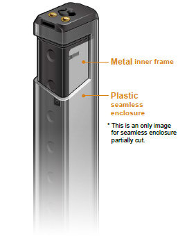
Plastic × metal
The SF4B-C series features a proprietary double structure of a "plastic body" with a "metal inner frame" which lightens the weight while maintaining the durability.
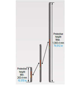
Maximum protective height of 1,943.4 mm 76.512 in
Despite its compact, plastic body, the SF4B-C series features a metal inner frame that increases toughness and also keeps its enclosure not to curve.
Protective heights range from 263.4 mm to 1,943.4 mm 10.370 in to 76.512 in.
45% lighter* for easy installation in high places and when mounting long models
Thanks to its plastic body, the SF4B-C series is 45 % lighter* than previous models with aluminum enclosures.
This helps to reduce the overall weight of the equipment during transport and when shipping it overseas.
* Comparing SF4B-H80<V2> with SF4B-H80CA-J05
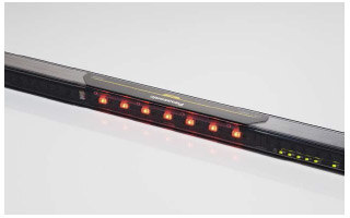
Large multi-purpose indicator SF4B-□CA-J05
The SF4B-C series is equipped with the large multi-purpose indicator at the center of the unit. The indicator shows the presence of the safety light curtain, helping to prevent unintentional beam interruption. The indicator can be used in a variety of applications such as a muting indicator and work indicator.
■Exceptional visibility with wide angle
The large multi-purpose indicator shines brightly through the plastic body to ensure exceptional visibility.

Muting control function for individual beams: Limit the muting area SF4B-□CA-J05
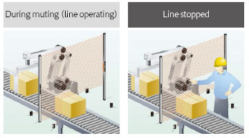
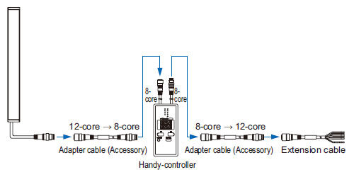
The SFB-HC handy-controller (optional) allows to perform muting control for certain beams. Since beam channels can be specified, so there is no need to install a guard to prevent intrusions. For example, according to the height of a sensing object, when muting control from the lowermost beam channel to the 10th beam channel is activated, the safety light curtain will detect any beam interruption at the 11th or higher beam channel as a human entry and stop the machinery.
Fixed blanking function: Choose active beam channels

The SFB-HC handy-controller (optional) provides a fixed blanking function that prevents control output (OSSD) from turning off even if certain beam channels are interrupted. This function is convenient for applications where an obstacle always interrupts certain beam channels.
Additionally, it is safe since control output (OSSD) is forcibly turned off in the event the obstruction moves outside the detection area.
Floating blanking function: Disable unspecified beams
*The min. sensing object will change when the floating blanking function is used.
The floating blanking function allows to disable up to three unspecified beam channels. Control output (OSSD) will not turn off as long as the number of interrupted beam channels is less than the set number of beam channels.
This function is convenient when an obstruction moves inside the detection area during setup changes or when loading materials within the detection area of safety light curtain.
* The min. sensing object will change when the floating blanking function is used.
Use output and indicators to achieve preventive maintenance when the incident light intensity gets unstable
By setting the auxiliary output switching function to off or on when light reception becomes unstable, the safety light curtain provides notification in the event of a reduction in the incident light intensity due to beam misalignment or dirt via auxiliary output (non-safety output) in addition to the incident light intensity indicator.
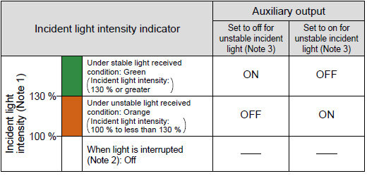
Notes:
1)An incident light intensity value of 100 % refers to the threshold value at which control outputs (OSSD1, OSSD2) change from off to on.
2)Interruption of the light refers to the presence of an object interrupts beam in the detection area.
3)This setting is not available when using muting control for individual beams, fixed blanking, or floating blanking.

PNP/NPN polarity support
Since a single model number can be switched between PNP and NPN input, fewer model numbers need to be registered.
Extraneous light check & avoid (ELCA) function
The ELCA function reduces interference without an interference prevention line.
External device monitor function
External devices (such as safety relays, etc.) can be directly connected to the handy-controller without any dedicated unit, simplifying installation, reducing costs, and helping to avoid various problems.
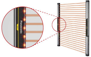
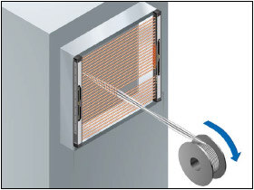
Beam-axis alignment indicator
Beam-axis alignment indicators are indicated in 4 blocks, allowing to see at a glance where light is being received.
Order guide
PRODUCT CONFIGURATION ORDER GUIDE
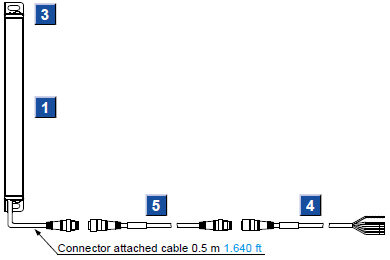
Pigtailed type (with muting function)
(with 0.5 m 1.640 ft connector attached cable)
Cable type
(with 5 m 16.404 ft cable)
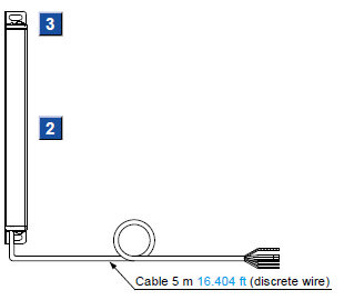
[1][2] Safety light curtains
Hand protection type
Min. sensing object ø25 mm ø0.984 in (20 mm 0.787 in beam pitch)
| Appearance | Operating range (Note 1) | Model No. (Note 2) | Number of beam channels | Protective height | |
|---|---|---|---|---|---|
| [1] Pigtailed type (with muting function) | [2] Cable type | ||||
| 0.3 to 7 m 0.984 to 22.966 ft | SF4B-H12CA-J05 | SF4B-H12C | 12 | 263.4 mm 10.370 in |
| SF4B-H16CA-J05 | SF4B-H16C | 16 | 343.4 mm 13.520 in | ||
| SF4B-H20CA-J05 | SF4B-H20C | 20 | 423.4 mm 16.669 in | ||
| SF4B-H24CA-J05 | SF4B-H24C | 24 | 503.4 mm 19.819 in | ||
| SF4B-H28CA-J05 | SF4B-H28C | 28 | 583.4 mm 22.969 in | ||
| SF4B-H32CA-J05 | SF4B-H32C | 32 | 663.4 mm 26.118 in | ||
| SF4B-H36CA-J05 | SF4B-H36C | 36 | 743.4 mm 29.268 in | ||
| SF4B-H40CA-J05 | SF4B-H40C | 40 | 823.4 mm 32.417 in | ||
| SF4B-H48CA-J05 | SF4B-H48C | 48 | 983.4 mm 38.717 in | ||
| SF4B-H56CA-J05 | SF4B-H56C | 56 | 1,143.4 mm 45.016 in | ||
| SF4B-H64CA-J05 | SF4B-H64C | 64 | 1,303.4 mm 51.315 in | ||
| SF4B-H72CA-J05 | SF4B-H72C | 72 | 1,463.4 mm 57.614 in | ||
| SF4B-H80CA-J05 | SF4B-H80C | 80 | 1,623.4 mm 63.913 in | ||
| SF4B-H88CA-J05 | SF4B-H88C | 88 | 1,783.4 mm 70.212 in | ||
| SF4B-H96CA-J05 | SF4B-H96C | 96 | 1,943.4 mm 76.512 in | ||
Arm / Foot protection type
Min. sensing object ø45 mm ø1.772 in (40 mm 1.575 in beam pitch)
| Appearance | Operating range (Note 1) | Model No. (Note 2) | Number of beam channels | Protective height | |
|---|---|---|---|---|---|
| [1] Pigtailed type (with muting function) | [2] Cable type | ||||
| 0.3 to 7 m 0.984 to 22.966 ft | SF4B-A8CA-J05 | SF4B-A8C | 8 | 343.4 mm 13.520 in |
| SF4B-A12CA-J05 | SF4B-A12C | 12 | 503.4 mm 19.819 in | ||
| SF4B-A16CA-J05 | SF4B-A16C | 16 | 663.4 mm 26.118 in | ||
| SF4B-A20CA-J05 | SF4B-A20C | 20 | 823.4 mm 32.417 in | ||
| SF4B-A24CA-J05 | SF4B-A24C | 24 | 983.4 mm 38.717 in | ||
| SF4B-A28CA-J05 | SF4B-A28C | 28 | 1,143.4 mm 45.016 in | ||
| SF4B-A32CA-J05 | SF4B-A32C | 32 | 1,303.4 mm 51.315 in | ||
| SF4B-A36CA-J05 | SF4B-A36C | 36 | 1,463.4 mm 57.614 in | ||
| SF4B-A40CA-J05 | SF4B-A40C | 40 | 1,623.4 mm 63.913 in | ||
| SF4B-A44CA-J05 | SF4B-A44C | 44 | 1,783.4 mm 70.212 in | ||
| SF4B-A48CA-J05 | SF4B-A48C | 48 | 1,943.4 mm 76.512 in | ||
Notes:
1) The operating range is the possible setting distance between the emitter and the receiver.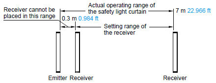
2) The model No. with "E" shown on the label affixed to the product is the emitter, "D" shown on the label is the receiver.
[3] Mounting brackets
Mounting bracket is not supplied with the safety light curtain. Be sure to order it separately.
| Designation | Appearance | Model No. | Description |
|---|---|---|---|
| Standard mounting bracket |
| MS-SF4BC-1 | Allows the safety light curtain to be mounted on the rear or side of the target equipment. Designed for use with one M5 hexagon-socket head bolt. (4 pcs. per set for the emitter and receiver) |
| Rear utility mounting bracket |
| MS-SF4BC-2 | Allows the safety light curtain to be mounted on the rear of the target equipment. Allows beam adjustment. Designed for use with one M5 hexagon-socket head bolt. For space-saving mounting, use one M5 hexagon head bolt. (4 pcs. per set for the emitter and receiver) |
| Side utility mounting bracket |
| MS-SF4BC-3 | Allows the safety light curtain to be mounted on the side of the target equipment. Allows beam adjustment. Designed for use with one M5 hexagon-socket head bolt. For space-saving mounting, use one M5 hexagon head bolt. (4 pcs. per set for the emitter and receiver) |
| Intermediate supporting bracket for utility mounting bracket (Note) |
| MS-SF4BC-4 | Supports the middle of the safety light curtain when installing it with utility mounting brackets. Allows the safety light curtain to be mounted on the rear or side of the target equipment. Allows beam adjustment. Designed for use with one M5 hexagon head bolt. (2 pcs. each per set for rear mounting and side mounting) |
| Intermediate supporting bracket for standard mounting bracket (Note) |
| MS-SF4BC-5 | Supports the middle of the safety light curtain when installing it with standard mounting brackets. Allows the safety light curtain to be mounted on the rear or side of the target equipment. Designed for use with two M3 countersunk screws. (2 pcs. each per set for rear mounting and side mounting) |
| Side mounting bracket |
| MS-SF4BC-6 | Allows beam axis alignment and the safety light curtain to be mounted on the device in confined spaces. Designed for use with one M5 hexagon-socket head bolt. (4 pcs. per set for the emitter and receiver) |
| Intermediate supporting bracket for use with side mounting bracket (Note) |
| MS-SF4BC-7 | Supports the middle of the safety light curtain when installing it with side mounting brackets. Allows beam axis alignment and the safety light curtain to be mounted on the device in confined spaces. Designed for use with one M5 hexagon-socket head bolt. (2 pces. per set) |
Note:
The numbers of sets required by SF4B-H□C (A-J05) (40 or more beam axes) and SF4B-A□C (A-J05) (20 or more beam axes) are as follows:
SF4B-H40C (A-J05), SF4B-H48C (A-J05), SF4B-H56C (A-J05), SF4B-A20C (A-J05), SF4B-A24C (A-J05), SF4B-A28C (A-J05): 1 set
SF4B-H64C (A-J05), SF4B-H72C (A-J05), SF4B-H80C (A-J05), SF4B-H88C (A-J05), SF4B-H96C (A-J05), SF4B-A32C (A-J05), SF4B-A36C (A-J05), SF4B-A40C (A-J05), SF4B-A44C (A-J05), SF4B-A48C (A-J05): 2 sets
Standard mounting bracket and intermediate supporting bracket for standard mounting bracket
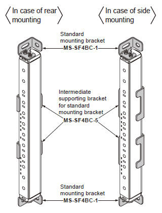
・ MS-SF4BC-1
Four brackets (two each R and L type) per set
[Eight M3 (length: 5 mm 0.197 in) hexagon-socket head bolts and four M5 flat washers are attached.]
・ MS-SF4BC-5
Two pcs. for rear mounting, two pcs. for side mounting
Rear utility mounting bracket and intermediate supporting bracket for utility mounting bracket
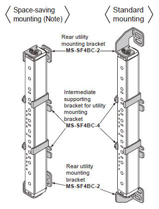
・ MS-SF4BC-2
Four brackets (two each R and L type) per set
[Eight M3 (length: 6 mm 0.236 in) hexagon-socket head bolts and four M5 flat washers are attached.]
・ MS-SF4BC-4
Two brackets per set[M5 flat washers, two pcs. assembled M3 (length: 6 mm 0.236 in) hexagon-socket head bolts for rear mounting, two pcs. attachments for side mounting.]
Side utility mounting bracket and intermediate supporting bracket for utility mounting bracket
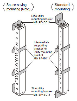
・ MS-SF4BC-3
Four brackets (two each R and L type) per set
[Eight M3 (length: 6 mm 0.236 in) hexagon-socket head bolts and four M5 flat washers are attached.]
・ MS-SF4BC-4
Two brackets per set[M5 flat washers, two pcs. assembled M3 (length: 6 mm 0.236 in) hexagon-socket head bolts for rear mounting, two pcs. attachments for side mounting.]
Note: For space-saving mounting, use an M5 hexagon head bolt
Side mounting bracket and Intermediate supporting bracket for side mounting bracket
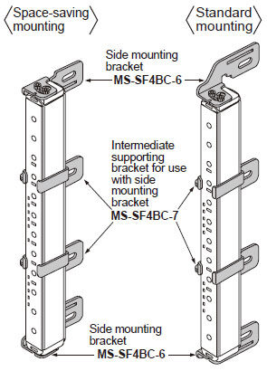
・ MS-SF4BC-6
Four brackets (two each R and L type) per set
[Eight M3 (length: 6 mm 0.236 in) hexagon-socket head bolts and four M5 flat washers are attached.]
・ MS-SF4BC-7
Two brackets per set[Two pcs. M5 flat washers, two pcs. assembled M3 (length: 6mm 0.236 in hexagon-socket head bolts for side mounting.]
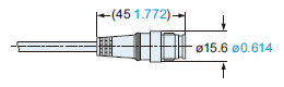
[4][5] Mating cables
| Type | Appearance | Model No. | Description | ||
|---|---|---|---|---|---|
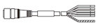
| [4] With connector on one end |
| SFB-CC3-MU | Length: 3 m 9.843 ft Net weight: 430 g approx. (2 cables) | Cable with connector on one end for pigtailed type (with muting function) Two cables per set for emitter and receiver Cable color: Gray for emitter, Gray with black line for receiver Connector color: Gray for emitter, Black for receiver Min. bending radius: R6 mm R0.236 in | |
| SFB-CC7-MU | Length: 7 m 22.966 ft Net weight: 1,000 g approx. (2 cables) | ||||
| SFB-CC10-MU | Length: 10 m 32.808 ft Net weight: 1,300 g approx. (2 cables) | ||||
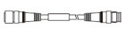
| [5] With connectors on both ends | For emitter |
| SFB-CCJ3E-MU | Length: 3 m 9.843 ft Net weight: 190 g approx. (1 cable) | Cable with connectors on both ends for pigtailed type (with muting function) Cable color: Gray (for emitter), Gray with black line for receiver Connector color: Gray for emitter, Black for receiver Min. bending radius: R6 mm R0.236 in |
| SFB-CCJ10E-MU | Length: 10 m 32.808 ft Net weight: 660 g approx. (1 cable) | ||||
| For receiver | SFB-CCJ3D-MU | Length: 3 m 9.843 ft Net weight: 210 g approx. (1 cable) | |||
| SFB-CCJ10D-MU | Length: 10 m 32.808 ft Net weight: 680 g approx. (1 cable) | ||||
Spare parts (Accessories for safety light curtain)
| Designation | Model No. | Description |
|---|---|---|
| Test rod ø25 | SF4B-TR25 | Min. sensing object for regular checking (ø25 mm ø0.984 in), for hand protection type (min. sensing object ø25 mm ø0.984 in) |
Option
Control unit
| Designation | Appearance | Model No. | Description |
|---|---|---|---|
| Slim type control unit |
| SF-C13 | Use a discrete wire cable to connect to the safety light curtain. Muting function can be used. Compatible with up to Control Category 4. When connecting pigtailed type (with muting function) SF4B-□CA-J05, be sure to order a mating cable separately. ・Mating cable: SFB-CC□-MU ・Extension cable: SFB-CCJ□-MU |
Handy-controller
| Designation | Appearance | Model No. |
|---|---|---|
| Handy- controller |
* 2 adapter cables included | SFB-HC |
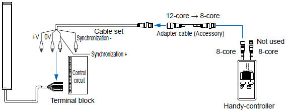
| Cable set for cable type connection |
| SFC-WNC1 |

Pigtailed type (with muting function)
Cable type
Metal protection cases
| Designation | Applicable beam channels | Appearance | Model No. | |
|---|---|---|---|---|
| Hand protection type | Arm / Foot protection type | |||
| Metal Protection Case for SF4B-C safety light curtain (One pair set for the emitter and the receiver) | 12 | - |
| MS-SF4BCH-12 |
| 16 | 8 | MS-SF4BCH-16 | ||
| 20 | - | MS-SF4BCH-20 | ||
| 24 | 12 | MS-SF4BCH-24 | ||
| 28 | - | MS-SF4BCH-28 | ||
| 32 | 16 | MS-SF4BCH-32 | ||
| 36 | - | MS-SF4BCH-36 | ||
| 40 | 20 | MS-SF4BCH-40 | ||
| 48 | 24 | MS-SF4BCH-48 | ||
| 56 | 28 | MS-SF4BCH-56 | ||
| 64 | 32 | MS-SF4BCH-64 | ||
| 72 | 36 | MS-SF4BCH-72 | ||
| 80 | 40 | MS-SF4BCH-80 | ||
| 88 | 44 | MS-SF4BCH-88 | ||
| 96 | 48 | MS-SF4BCH-96 | ||
Note: In the case of using a metal protection case MS-SF4BCH-□(optional), make sure to assemble it with a standard mounting bracket MS-SF4BC-1 (optional).
Others
| Designation | Model No. | Description |
|---|---|---|
| Test rod ø45 | SF4B-TR45 | Min. sensing object for regular checking (ø45 mm ø1.772 in), for arm / foot protection type (min. sensing object ø45 mm ø1.772 in) |
| Large display unit for safety light curtain | SF-IND-2 | With the auxiliary output of the safety light curtain, the operation is easily observable from various directions. <Specifications> ・Supply voltage: 24 V DC ±15 % ・Current consumption: 12 mA or less ・Indicators: Orange LED (8 pcs. used) [Light up when external contact is ON] ・Ambient temperature: -10 to +55 ℃ +14 to +131 ℉ (No dew condensation or icing allowed) ・Material: POM (Enclosure), Polycarbonate (Cover), Cold rolled carbon steel (SPCC) (Bracket) ・Cable: 0.3 mm2 2-core cabtyre cable, 3 m 9.843 ft long ・Weight: 70 g approx. (including bracket) |
Large display unit for safety light curtain
・SF-IND-2
* Cannot be attached together with a mounting bracket to the safety light curtain using a single bolt.
Recommended safety relay
SF relay, slim type
SF series
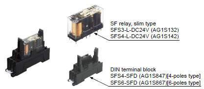
Note:Please contactour sales officefor details on the recommended products.
| Type | With LED indicator | |
|---|---|---|
| Model No. | SFS3-L-DC24V | SFS4-L-DC24V |
| Part No. | AG1S132 | AG1S142 |
| Contact arrangement | 3a1b | 4a2b |
| Rated nominal switching capacity | 6A/250V AC、6A/30V DC | |
| Min. switching capacity | 1mA/5V DC | |
| Coil rating | 15mA/24V DC | 20.8mA/24V DC |
| Rated power consumption | 360mW | 500mW |
| Operation time | 20ms or less | |
| Release time | 20ms or less | |
| Ambient temperature | -40 to +85 ℃ -40 to + 185 ℉ (Humidity: 5 to 85 % RH) | |
| Applicable certifications | UL/c-UL, TÜV, Korea S-mark | |
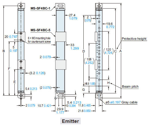
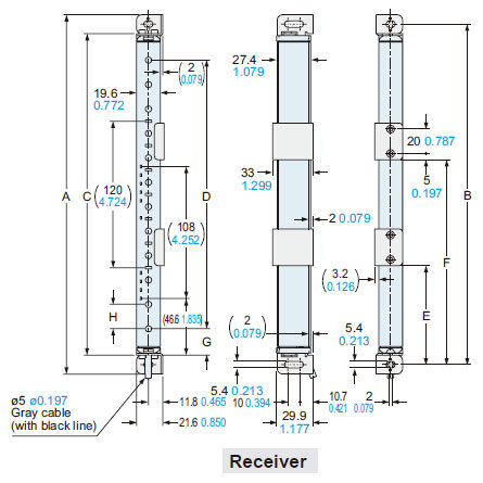
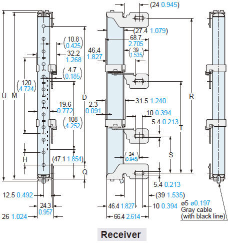
Dimensions
- Unit: mm in
SF4B-□CA-J05
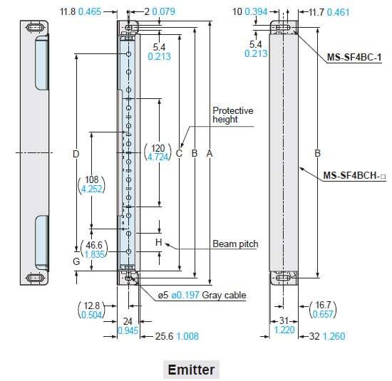
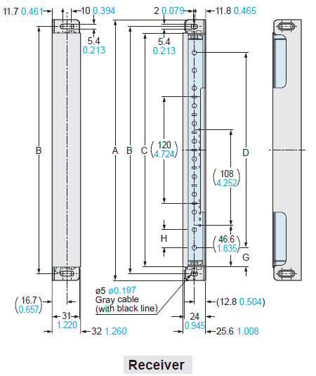
SF4B-□C
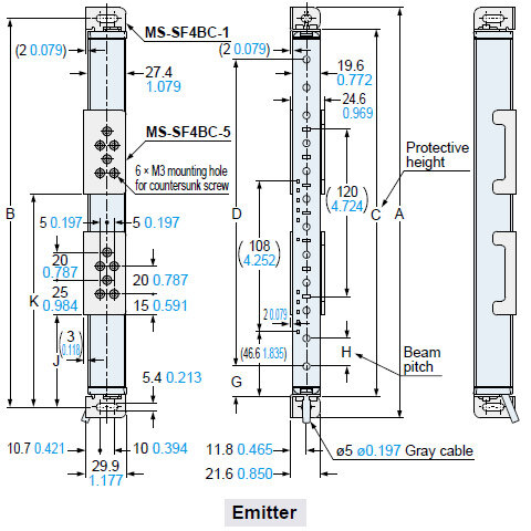
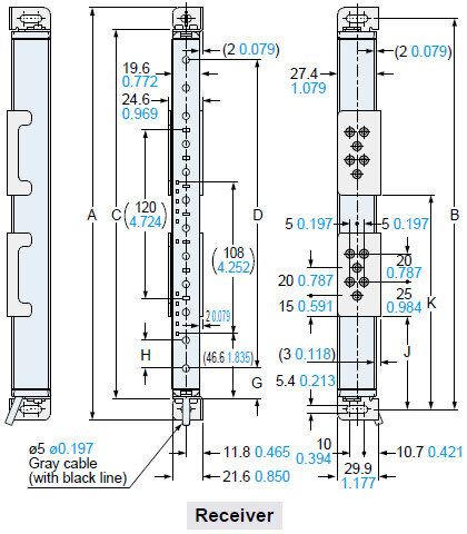
Safety light curtain
Assembly dimensions
The figure depicts rear mounting using the standard mounting bracket MS-SF4BC-1 (optional) and the intermediate supporting bracket for standard mounting bracket MS-SF4BC-5 (optional).
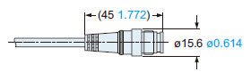
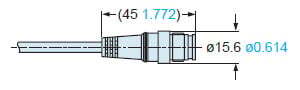
<Connector of the pigtailed type (with muting function) SF4B-□CA-J05>
| Model No. | A | B | C | D | E | F | ||
|---|---|---|---|---|---|---|---|---|
| SF4B-H□C (A-J05) | SF4B-A□C (A-J05) | |||||||
| SF4B-H12C(A-J05) | - | 294.4 11.591 | 279 10.984 | 263.4 10.370 | 220 8.661 | - | - | - |
| SF4B-H16C(A-J05) | SF4B-A8C(A-J05) | 374.4 14.740 | 359 14.134 | 343.4 13.520 | 300 11.811 | 280 11.024 | - | - |
| SF4B-H20C(A-J05) | - | 454.4 17.890 | 439 17.283 | 423.4 16.669 | 380 14.961 | - | - | - |
| SF4B-H24C(A-J05) | SF4B-A12C(A-J05) | 534.4 21.039 | 519 20.433 | 503.4 19.819 | 460 18.110 | 440 17.323 | - | - |
| SF4B-H28C(A-J05) | - | 614.4 24.189 | 599 23.583 | 583.4 22.969 | 540 21.260 | - | - | - |
| SF4B-H32C(A-J05) | SF4B-A16C(A-J05) | 694.4 27.339 | 679 26.732 | 663.4 26.118 | 620 24.409 | 600 23.622 | - | - |
| SF4B-H36C(A-J05) | - | 774.4 30.488 | 759 29.882 | 743.4 29.268 | 700 27.559 | - | - | - |
| SF4B-H40C(A-J05) | SF4B-A20C(A-J05) | 854.4 33.638 | 839 33.031 | 823.4 32.417 | 780 30.709 | 760 29.921 | 395 15.551 | - |
| SF4B-H48C(A-J05) | SF4B-A24C(A-J05) | 1,014.4 39.937 | 999 39.331 | 983.4 38.717 | 940 37.008 | 920 36.220 | 475 18.701 | - |
| SF4B-H56C(A-J05) | SF4B-A28C(A-J05) | 1,174.4 46.236 | 1,159 45.630 | 1,143.4 45.016 | 1,100 43.307 | 1,080 42.520 | 555 21.850 | - |
| SF4B-H64C(A-J05) | SF4B-A32C(A-J05) | 1,334.4 52.535 | 1,319 51.929 | 1,303.4 51.315 | 1,260 49.606 | 1,240 48.819 | 415 16.339 | 854 33.622 |
| SF4B-H72C(A-J05) | SF4B-A36C(A-J05) | 1,494.4 58.835 | 1,479 58.228 | 1,463.4 57.614 | 1,420 55.906 | 1,400 55.118 | 468 18.425 | 961 37.835 |
| SF4B-H80C(A-J05) | SF4B-A40C(A-J05) | 1,654.4 65.134 | 1,639 64.528 | 1,623.4 63.913 | 1,580 62.205 | 1,560 61.417 | 521 20.512 | 1,068 42.047 |
| SF4B-H88C(A-J05) | SF4B-A44C(A-J05) | 1,814.4 71.433 | 1,799 70.827 | 1,783.4 70.212 | 1,740 68.504 | 1,720 67.716 | 574 22.598 | 1,175 46.260 |
| SF4B-H96C(A-J05) | SF4B-A48C(A-J05) | 1,974.4 77.732 | 1,959 77.126 | 1,943.4 76.512 | 1,900 74.803 | 1,880 74.016 | 627 24.685 | 1,282 50.472 |
| Model No. | G | H |
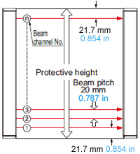
|---|---|---|
| SF4B-H□C(A-J05) | 21.7 0.854 | 20 0.787 |
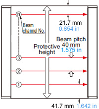
| SF4B-A□C(A-J05) | 41.7 1.642 | 40 1.575 |
Assembly dimensions
The figure depicts side mounting using the standard mounting bracket MS-SF4BC-1 (optional) and the intermediate supporting bracket for standard mounting bracket MS-SF4BC-5 (optional).
| Model No. | A | B | C | D | J | K | ||
|---|---|---|---|---|---|---|---|---|
| SF4B-H□C (A-J05) | SF4B-A□C (A-J05) | |||||||
| SF4B-H12C(A-J05) | - | 294.4 11.591 | 279 10.984 | 263.4 10.370 | 220 8.661 | - | - | - |
| SF4B-H16C(A-J05) | SF4B-A8C(A-J05) | 374.4 14.740 | 359 14.134 | 343.4 13.520 | 300 11.811 | 280 11.024 | - | - |
| SF4B-H20C(A-J05) | - | 454.4 17.890 | 439 17.283 | 423.4 16.669 | 380 14.961 | - | - | - |
| SF4B-H24C(A-J05) | SF4B-A12C(A-J05) | 534.4 21.039 | 519 20.433 | 503.4 19.819 | 460 18.110 | 440 17.323 | - | - |
| SF4B-H28C(A-J05) | - | 614.4 24.189 | 599 23.583 | 583.4 22.969 | 540 21.260 | - | - | - |
| SF4B-H32C(A-J05) | SF4B-A16C(A-J05) | 694.4 27.339 | 679 26.732 | 663.4 26.118 | 620 24.409 | 600 23.622 | - | - |
| SF4B-H36C(A-J05) | - | 774.4 30.488 | 759 29.882 | 743.4 29.268 | 700 27.559 | - | - | - |
| SF4B-H40C(A-J05) | SF4B-A20C(A-J05) | 854.4 33.638 | 839 33.031 | 823.4 32.417 | 780 30.709 | 760 29.921 | 390 15.354 | - |
| SF4B-H48C(A-J05) | SF4B-A24C(A-J05) | 1,014.4 39.937 | 999 39.331 | 983.4 38.717 | 940 37.008 | 920 36.220 | 470 18.504 | - |
| SF4B-H56C(A-J05) | SF4B-A28C(A-J05) | 1,174.4 46.236 | 1,159 45.630 | 1,143.4 45.016 | 1,100 43.307 | 1,080 42.520 | 550 21.654 | - |
| SF4B-H64C(A-J05) | SF4B-A32C(A-J05) | 1,334.4 52.535 | 1,319 51.929 | 1,303.4 51.315 | 1,260 49.606 | 1,240 48.819 | 410 16.142 | 849 33.425 |
| SF4B-H72C(A-J05) | SF4B-A36C(A-J05) | 1,494.4 58.835 | 1,479 58.228 | 1,463.4 57.614 | 1,420 55.906 | 1,400 55.118 | 463 18.228 | 956 37.638 |
| SF4B-H80C(A-J05) | SF4B-A40C(A-J05) | 1,654.4 65.134 | 1,639 64.528 | 1,623.4 63.913 | 1,580 62.205 | 1,560 61.417 | 516 20.315 | 1,063 |
| SF4B-H88C(A-J05) | SF4B-A44C(A-J05) | 1,814.4 71.433 | 1,799 70.827 | 1,783.4 70.212 | 1,740 68.504 | 1,720 67.716 | 569 22.402 | 1,170 |
| SF4B-H96C(A-J05) | SF4B-A48C(A-J05) | 1,974.4 77.732 | 1,959 77.126 | 1,943.4 76.512 | 1,900 62.205 | 1,880 74.016 | 622 24.488 | 1,277 |
| Model No. | G | H |
|---|---|---|
| SF4B-H□C(A-J05) | 21.7 0.854 | 20 0.787 |
| SF4B-A□C(A-J05) | 41.7 1.642 | 40 1.575 |
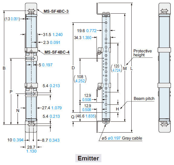
Assembly dimensions
The figure depicts rear mounting using the rear utility mounting bracket MS-SF4BC-2 (optional) and the intermediate supporting bracket for utility mounting bracket MS-SF4BC-4 (optional).
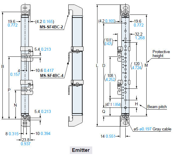
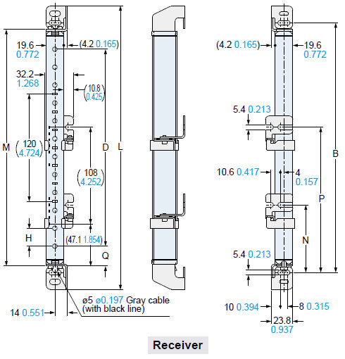
<Connector of the pigtailed type (with muting function) SF4B-□CA-J05>

| Model No. | B | D | L | M | N | P | ||
|---|---|---|---|---|---|---|---|---|
| SF4B-H□C (A-J05) | SF4B-A□C (A-J05) | |||||||
| SF4B-H12C(A-J05) | - | 279 10.984 | 220 8.661 | - | 316.4 12.457 | 264.4 10.409 | - | - |
| SF4B-H16C(A-J05) | SF4B-A8C(A-J05) | 359 14.134 | 300 11.811 | 280 11.024 | 396.4 15.606 | 344.4 13.559 | - | - |
| SF4B-H20C(A-J05) | - | 439 17.283 | 380 14.961 | - | 476.4 18.756 | 424.4 16.709 | - | - |
| SF4B-H24C(A-J05) | SF4B-A12C(A-J05) | 519 20.433 | 460 18.110 | 440 17.323 | 556.4 21.906 | 504.4 19.858 | - | - |
| SF4B-H28C(A-J05) | - | 599 23.583 | 540 21.260 | - | 636.4 25.055 | 584.4 23.008 | - | - |
| SF4B-H32C(A-J05) | SF4B-A16C(A-J05) | 679 26.732 | 620 24.409 | 600 23.622 | 716.4 28.205 | 664.4 26.157 | - | - |
| SF4B-H36C(A-J05) | - | 759 29.882 | 700 27.559 | - | 796.4 31.354 | 744.4 29.307 | - | - |
| SF4B-H40C(A-J05) | SF4B-A20C(A-J05) | 839 33.031 | 780 30.709 | 760 29.921 | 876.4 34.504 | 824.4 32.457 | 399.5 15.728 | - |
| SF4B-H48C(A-J05) | SF4B-A24C(A-J05) | 999 39.331 | 940 37.008 | 920 36.220 | 1,036.4 40.803 | 984.4 38.756 | 479.5 18.878 | - |
| SF4B-H56C(A-J05) | SF4B-A28C(A-J05) | 1,159 45.630 | 1,100 43.307 | 1,080 42.520 | 1,196.4 47.102 | 1,144.4 45.055 | 559.5 22.028 | - |
| SF4B-H64C(A-J05) | SF4B-A32C(A-J05) | 1,319 51.929 | 1,260 49.606 | 1,240 48.819 | 1,356.4 53.402 | 1,304.4 51.354 | 419.5 16.516 | 858.5 33.799 |
| SF4B-H72C(A-J05) | SF4B-A36C(A-J05) | 1,479 58.228 | 1,420 55.906 | 1,400 55.118 | 1,516.4 59.701 | 1,464.4 57.654 | 472.5 18.602 | 965.5 38.012 |
| SF4B-H80C(A-J05) | SF4B-A40C(A-J05) | 1,639 64.528 | 1,580 62.205 | 1,560 61.417 | 1,676.4 66.000 | 1,624.4 63.953 | 525.5 20.689 | 1,072.5 42.224 |
| SF4B-H88C(A-J05) | SF4B-A44C(A-J05) | 1,799 70.827 | 1,740 68.504 | 1,720 67.716 | 1,836.4 72.299 | 1,784.4 70.252 | 578.5 22.776 | 1,179.5 46.437 |
| SF4B-H96C(A-J05) | SF4B-A48C(A-J05) | 1,959 77.126 | 1,900 74.803 | 1,880 74.016 | 1,996.4 78.598 | 1,944.4 76.551 | 631.5 24.862 | 1,286.5 50.650 |
| Model No. | H | Q |
|---|---|---|
| SF4B-H□C(A-J05) | 20 0.787 | 22.2 0.874 |
| SF4B-A□C(A-J05) | 40 1.575 | 42.2 1.661 |
Assembly dimensions
The figure depicts space-saving mounting using the rear utility mounting bracket MS-SF4BC-2 (optional) and the intermediate supporting bracket for utility mounting bracket MS-SF4BC-4 (optional).
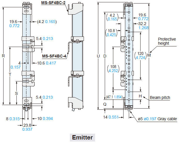
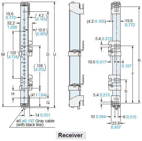
<Connector of the pigtailed type (with muting function) SF4B-□CA-J05>

| Model No. | D | M | R | S | T | U | ||
|---|---|---|---|---|---|---|---|---|
| SF4B-H□C (A-J05) | SF4B-A□C (A-J05) | |||||||
| SF4B-H12C(A-J05) | - | 220 8.661 | - | 264.4 10.409 | 245.8 9.677 | - | - | 270.4 10.646 |
| SF4B-H16C(A-J05) | SF4B-A8C(A-J05) | 300 11.811 | 280 11.024 | 344.4 13.559 | 325.8 12.827 | - | - | 350.4 13.795 |
| SF4B-H20C(A-J05) | - | 380 14.961 | - | 424.4 16.709 | 405.8 17.748 | - | - | 430.4 16.945 |
| SF4B-H24C(A-J05) | SF4B-A12C(A-J05) | 460 18.110 | 440 17.323 | 504.4 19.858 | 485.8 19.126 | - | - | 510.4 20.094 |
| SF4B-H28C(A-J05) | - | 540 21.260 | - | 584.4 23.008 | 565.8 22.276 | - | - | 590.4 23.244 |
| SF4B-H32C(A-J05) | SF4B-A16C(A-J05) | 620 24.409 | 600 23.622 | 664.4 26.157 | 645.8 25.425 | - | - | 670.4 26.394 |
| SF4B-H36C(A-J05) | - | 700 27.559 | - | 744.4 29.307 | 725.8 28.575 | - | - | 750.4 29.543 |
| SF4B-H40C(A-J05) | SF4B-A20C(A-J05) | 780 30.709 | 760 29.921 | 824.4 32.457 | 805.8 31.724 | 382.9 15.075 | - | 830.4 32.693 |
| SF4B-H48C(A-J05) | SF4B-A24C(A-J05) | 940 37.008 | 920 36.220 | 984.4 38.756 | 965.8 38.024 | 462.9 18.224 | - | 990.4 38.992 |
| SF4B-H56C(A-J05) | SF4B-A28C(A-J05) | 1,100 43.307 | 1,080 42.520 | 1,144.4 45.055 | 1,125.8 44.323 | 542.9 21.374 | - | 1,150.4 45.291 |
| SF4B-H64C(A-J05) | SF4B-A32C(A-J05) | 1,260 49.606 | 1,240 48.819 | 1,304.4 51.354 | 1,285.8 50.622 | 402.9 15.862 | 841.9 33.146 | 1,310.4 51.590 |
| SF4B-H72C(A-J05) | SF4B-A36C(A-J05) | 1,420 55.906 | 1,400 55.118 | 1,464.4 57.654 | 1,445.8 56.921 | 455.9 17.949 | 948.9 37.358 | 1,470.4 57.890 |
| SF4B-H80C(A-J05) | SF4B-A40C(A-J05) | 1,580 62.205 | 1,560 61.417 | 1,624.4 63.953 | 1,605.8 63.220 | 508.9 20.035 | 1,055.9 41.571 | 1,630.4 64.189 |
| SF4B-H88C(A-J05) | SF4B-A44C(A-J05) | 1,740 68.504 | 1,720 67.716 | 1,784.4 70.252 | 1,765.8 69.520 | 561.9 22.122 | 1,162.9 45.783 | 1,790.4 70.488 |
| SF4B-H96C(A-J05) | SF4B-A48C(A-J05) | 1,900 74.803 | 1,880 74.016 | 1,944.4 76.551 | 1,925.8 75.819 | 614.9 24.209 | 1,269.9 49.996 | 1,950.4 76.787 |
| Model No. | H | Q |
|---|---|---|
| SF4B-H□C(A-J05) | 20 0.787 | 22.2 0.874 |
| SF4B-A□C(A-J05) | 40 1.575 | 42.2 1.661 |
Assembly dimensions
The figure depicts side mounting using the side utility mounting bracket MS-SF4BC-3 (optional) and the intermediate supporting bracket for utility mounting bracket MS-SF4BC-4 (optional).
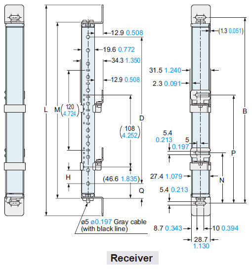
<Connector of the pigtailed type (with muting function) SF4B-□CA-J05>

| Model No. | B | D | L | M | N | P | ||
|---|---|---|---|---|---|---|---|---|
| SF4B-H□C (A-J05) | SF4B-A□C (A-J05) | |||||||
| SF4B-H12C(A-J05) | - | 279 10.984 | 220 8.661 | - | 316.4 12.457 | 264.4 10.409 | - | - |
| SF4B-H16C(A-J05) | SF4B-A8C(A-J05) | 359 14.134 | 300 11.811 | 280 11.024 | 396.4 15.606 | 344.4 13.559 | - | - |
| SF4B-H20C(A-J05) | - | 439 17.283 | 380 14.961 | - | 476.4 18.756 | 424.4 16.709 | - | - |
| SF4B-H24C(A-J05) | SF4B-A12C(A-J05) | 519 20.433 | 460 18.110 | 440 17.323 | 556.4 21.906 | 504.4 19.858 | - | - |
| SF4B-H28C(A-J05) | - | 599 23.583 | 540 21.260 | - | 636.4 25.055 | 584.4 23.008 | - | - |
| SF4B-H32C(A-J05) | SF4B-A16C(A-J05) | 679 26.732 | 620 24.409 | 600 23.622 | 716.4 28.205 | 664.4 26.157 | - | - |
| SF4B-H36C(A-J05) | - | 759 29.882 | 700 27.559 | - | 796.4 31.354 | 744.4 29.307 | - | - |
| SF4B-H40C(A-J05) | SF4B-A20C(A-J05) | 839 33.031 | 780 30.709 | 760 29.921 | 876.4 34.504 | 824.4 32.457 | 399.5 15.728 | - |
| SF4B-H48C(A-J05) | SF4B-A24C(A-J05) | 999 39.331 | 940 37.008 | 920 36.220 | 1,036.4 40.803 | 984.4 38.756 | 479.5 18.878 | - |
| SF4B-H56C(A-J05) | SF4B-A28C(A-J05) | 1,159 45.630 | 1,100 43.307 | 1,080 42.520 | 1,196.4 47.102 | 1,144.4 45.055 | 559.5 22.028 | - |
| SF4B-H64C(A-J05) | SF4B-A32C(A-J05) | 1,319 51.929 | 1,260 49.606 | 1,240 48.819 | 1,356.4 53.402 | 1,304.4 51.354 | 419.5 16.516 | 858.5 33.799 |
| SF4B-H72C(A-J05) | SF4B-A36C(A-J05) | 1,479 58.228 | 1,420 55.906 | 1,400 55.118 | 1,516.4 59.701 | 1,464.4 57.654 | 472.5 18.602 | 965.5 38.012 |
| SF4B-H80C(A-J05) | SF4B-A40C(A-J05) | 1,639 64.528 | 1,580 62.205 | 1,560 61.417 | 1,676.4 66.000 | 1,624.4 63.953 | 525.5 20.689 | 1,072.5 42.224 |
| SF4B-H88C(A-J05) | SF4B-A44C(A-J05) | 1,799 70.827 | 1,740 68.504 | 1,720 67.716 | 1,836.4 72.299 | 1,784.4 70.252 | 578.5 22.776 | 1,179.5 46.437 |
| SF4B-H96C(A-J05) | SF4B-A48C(A-J05) | 1,959 77.126 | 1,900 74.803 | 1,880 74.016 | 1,996.4 78.598 | 1,944.4 76.551 | 631.5 24.862 | 1,286.5 50.650 |
| Model No. | H | Q |
|---|---|---|
| SF4B-H□C(A-J05) | 20 0.787 | 22.2 0.874 |
| SF4B-A□C(A-J05) | 40 1.575 | 42.2 1.661 |
Assembly dimensions
The figure depicts space-saving mounting side utility mounting bracket MS-SF4BC-3 (optional) and the intermediate supporting bracket for utility mounting bracket MS-SF4BC-4 (optional).
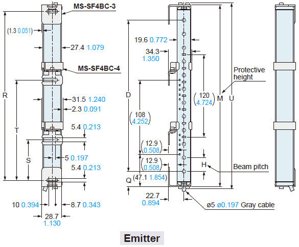
<Connector of the pigtailed type (with muting function) SF4B-□CA-J05>

| Model No. | D | M | R | S | T | U | ||
|---|---|---|---|---|---|---|---|---|
| SF4B-H□C (A-J05) | SF4B-A□C (A-J05) | |||||||
| SF4B-H12C(A-J05) | - | 220 8.661 | - | 264.4 10.409 | 245.8 9.677 | - | - | 270.4 10.646 |
| SF4B-H16C(A-J05) | SF4B-A8C(A-J05) | 300 11.811 | 280 11.024 | 344.4 13.559 | 325.8 12.827 | - | - | 350.4 13.795 |
| SF4B-H20C(A-J05) | - | 380 14.961 | - | 424.4 16.709 | 405.8 17.748 | - | - | 430.4 16.945 |
| SF4B-H24C(A-J05) | SF4B-A12C(A-J05) | 460 18.110 | 440 17.323 | 504.4 19.858 | 485.8 19.126 | - | - | 510.4 20.094 |
| SF4B-H28C(A-J05) | - | 540 21.260 | - | 584.4 23.008 | 565.8 22.276 | - | - | 590.4 23.244 |
| SF4B-H32C(A-J05) | SF4B-A16C(A-J05) | 620 24.409 | 600 23.622 | 664.4 26.157 | 645.8 25.425 | - | - | 670.4 26.394 |
| SF4B-H36C(A-J05) | - | 700 27.559 | - | 744.4 29.307 | 725.8 28.575 | - | - | 750.4 29.543 |
| SF4B-H40C(A-J05) | SF4B-A20C(A-J05) | 780 30.709 | 760 29.921 | 824.4 32.457 | 805.8 31.724 | 382.9 15.075 | - | 830.4 32.693 |
| SF4B-H48C(A-J05) | SF4B-A24C(A-J05) | 940 37.008 | 920 36.220 | 984.4 38.756 | 965.8 38.024 | 462.9 18.224 | - | 990.4 38.992 |
| SF4B-H56C(A-J05) | SF4B-A28C(A-J05) | 1,100 43.307 | 1,080 42.520 | 1,144.4 45.055 | 1,125.8 44.323 | 542.9 21.374 | - | 1,150.4 45.291 |
| SF4B-H64C(A-J05) | SF4B-A32C(A-J05) | 1,260 49.606 | 1,240 48.819 | 1,304.4 51.354 | 1,285.8 50.622 | 402.9 15.862 | 841.9 33.146 | 1,310.4 51.590 |
| SF4B-H72C(A-J05) | SF4B-A36C(A-J05) | 1,420 55.906 | 1,400 55.118 | 1,464.4 57.654 | 1,445.8 56.921 | 455.9 17.949 | 948.9 37.358 | 1,470.4 57.890 |
| SF4B-H80C(A-J05) | SF4B-A40C(A-J05) | 1,580 62.205 | 1,560 61.417 | 1,624.4 63.953 | 1,605.8 63.220 | 508.9 20.035 | 1,055.9 41.571 | 1,630.4 64.189 |
| SF4B-H88C(A-J05) | SF4B-A44C(A-J05) | 1,740 68.504 | 1,720 67.716 | 1,784.4 70.252 | 1,765.8 69.520 | 561.9 22.122 | 1,162.9 45.783 | 1,790.4 70.488 |
| SF4B-H96C(A-J05) | SF4B-A48C(A-J05) | 1,900 74.803 | 1,880 74.016 | 1,944.4 76.551 | 1,925.8 75.819 | 614.9 24.209 | 1,269.9 49.996 | 1,950.4 76.787 |
| Model No. | H | Q |
|---|---|---|
| SF4B-H□C(A-J05) | 20 0.787 | 22.2 0.874 |
| SF4B-A□C(A-J05) | 40 1.575 | 42.2 1.661 |
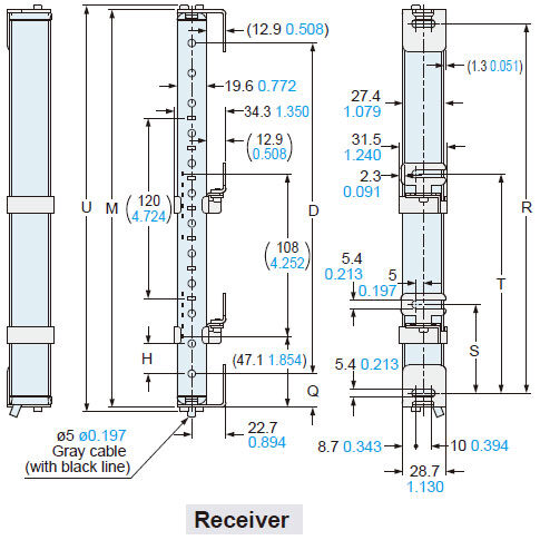
Assembly dimensions
The figure depicts using the side mounting bracket MS-SF4BC-6 (optional) and the Intermediate supporting bracket for side mounting bracket MS-SF4BC-7 (optional).
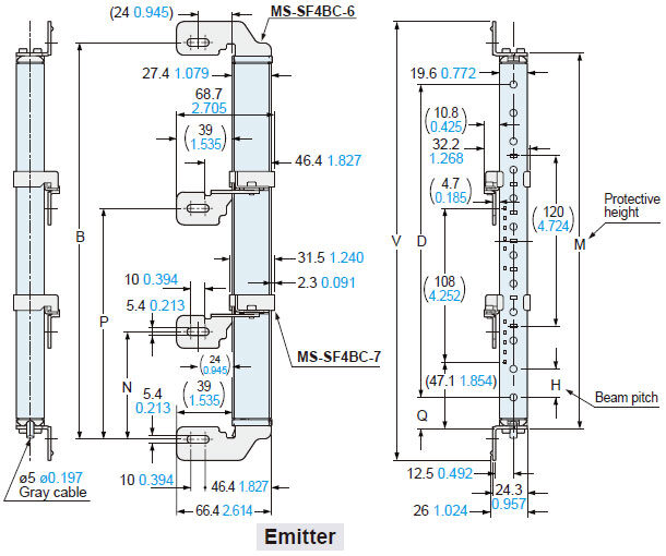
<Connector of the pigtailed type (with muting function) SF4B-□CA-J05>

| Model No. | B | D | M | N | P | V | ||
|---|---|---|---|---|---|---|---|---|
| SF4B-H□C (A-J05) | SF4B-A□C (A-J05) | |||||||
| SF4B-H12C(A-J05) | - | 279 10.984 | 220 8.661 | - | 264.4 10.409 | - | - | 308.4 12.142 |
| SF4B-H16C(A-J05) | SF4B-A8C(A-J05) | 359 14.134 | 300 11.811 | 280 11.024 | 344.4 13.559 | - | - | 388.4 15.291 |
| SF4B-H20C(A-J05) | - | 439 17.283 | 380 14.961 | - | 424.4 16.709 | - | - | 468.4 18.441 |
| SF4B-H24C(A-J05) | SF4B-A12C(A-J05) | 519 20.433 | 460 18.110 | 440 17.323 | 504.4 19.858 | - | - | 548.4 21.591 |
| SF4B-H28C(A-J05) | - | 599 23.583 | 54021.260 | - | 584.4 23.008 | - | - | 628.4 24.74 |
| SF4B-H32C(A-J05) | SF4B-A16C(A-J05) | 679 26.732 | 620 24.409 | 600 23.622 | 664.4 26.157 | - | - | 708.4 27.89 |
| SF4B-H36C(A-J05) | - | 759 29.882 | 700 27.559 | - | 744.4 29.307 | - | - | 788.4 31.039 |
| SF4B-H40C(A-J05) | SF4B-A20C(A-J05) | 839 33.031 | 780 30.709 | 760 29.921 | 824.4 32.457 | 399.5 15.728 | - | 868.4 34.189 |
| SF4B-H48C(A-J05) | SF4B-A24C(A-J05) | 999 39.331 | 940 37.008 | 920 36.220 | 984.4 38.756 | 479.5 18.878 | - | 1,028.4 40.488 |
| SF4B-H56C(A-J05) | SF4B-A28C(A-J05) | 1,159 45.630 | 1,100 43.307 | 1,080 42.520 | 1,144.4 45.055 | 559.5 22.028 | - | 1,188.4 46.787 |
| SF4B-H64C(A-J05) | SF4B-A32C(A-J05) | 1,319 51.929 | 1,260 49.606 | 1,240 48.819 | 1,304.4 51.354 | 419.5 16.516 | 858.5 33.799 | 1,348.4 53.087 |
| SF4B-H72C(A-J05) | SF4B-A36C(A-J05) | 1,479 58.228 | 1,420 55.906 | 1,400 55.118 | 1,464.4 57.654 | 472.5 18.602 | 965.5 38.012 | 1,508.4 59,386 |
| SF4B-H80C(A-J05) | SF4B-A40C(A-J05) | 1,639 64.528 | 1,580 62.205 | 1,560 61.417 | 1,624.4 63.953 | 525.5 20.689 | 1,072.5 42.224 | 1,668.4 65.685 |
| SF4B-H88C(A-J05) | SF4B-A44C(A-J05) | 1,799 70.827 | 1,740 68.504 | 1,720 67.716 | 1,784.4 70.252 | 578.5 22.776 | 1,179.5 46.437 | 1,828.4 71.984 |
| SF4B-H96C(A-J05) | SF4B-A48C(A-J05) | 1,959 77.126 | 1,900 74.803 | 1,880 74.016 | 1,944.4 76.551 | 631.5 24.862 | 1,286.5 50.650 | 1,988.4 78.283 |
| Model No. | H | Q |
|---|---|---|
| SF4B-H□C(A-J05) | 20 0.787 | 22.2 0.874 |
| SF4B-A□C(A-J05) | 40 1.575 | 42.2 1.661 |
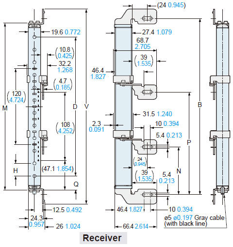
Assembly dimensions
The figure depicts space-saving mounting using the side mounting bracket MS-SF4BC-6 (optional) and the Intermediate supporting bracket for side mounting bracket MS-SF4BC-7 (optional).
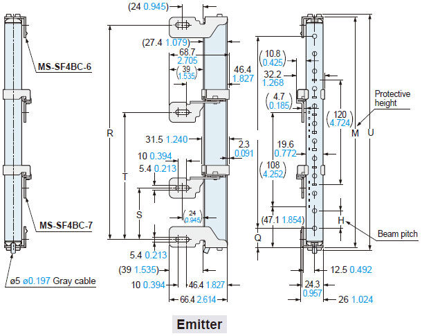
<Connector of the pigtailed type (with muting function) SF4B-□CA-J05>
| Model No. | D | M | R | S | T | U | ||
|---|---|---|---|---|---|---|---|---|
| SF4B-H□C (A-J05) | SF4B-A□C (A-J05) | |||||||
| SF4B-H12C(A-J05) | - | 220 8.661 | - | 264.4 10.409 | 245.8 9.677 | - | - | 270.4 10.646 |
| SF4B-H16C(A-J05) | SF4B-A8C(A-J05) | 300 11.811 | 280 11.024 | 344.4 13.559 | 325.8 12.827 | - | - | 350.4 13.795 |
| SF4B-H20C(A-J05) | - | 380 14.961 | - | 424.4 16.709 | 405.8 17.748 | - | - | 430.4 16.945 |
| SF4B-H24C(A-J05) | SF4B-A12C(A-J05) | 460 18.110 | 440 17.323 | 504.4 19.858 | 485.8 19.126 | - | - | 510.4 20.094 |
| SF4B-H28C(A-J05) | - | 540 21.260 | - | 584.4 23.008 | 565.8 22.276 | - | - | 590.4 23.244 |
| SF4B-H32C(A-J05) | SF4B-A16C(A-J05) | 620 24.409 | 600 23.622 | 664.4 26.157 | 645.8 25.425 | - | - | 670.4 26.394 |
| SF4B-H36C(A-J05) | - | 700 27.559 | - | 744.4 29.307 | 725.8 28.575 | - | - | 750.4 29.543 |
| SF4B-H40C(A-J05) | SF4B-A20C(A-J05) | 780 30.709 | 760 29.921 | 824.4 32.457 | 805.8 31.724 | 382.9 15.075 | - | 830.4 32.693 |
| SF4B-H48C(A-J05) | SF4B-A24C(A-J05) | 940 37.008 | 920 36.220 | 984.4 38.756 | 965.8 38.024 | 462.9 18.224 | - | 990.4 38.992 |
| SF4B-H56C(A-J05) | SF4B-A28C(A-J05) | 1,100 43.307 | 1,080 42.520 | 1,144.4 45.055 | 1,125.8 44.323 | 542.9 21.374 | - | 1,150.4 45.291 |
| SF4B-H64C(A-J05) | SF4B-A32C(A-J05) | 1,260 49.606 | 1,240 48.819 | 1,304.4 51.354 | 1,285.8 50.622 | 402.9 15.862 | 841.9 33.146 | 1,310.4 51.590 |
| SF4B-H72C(A-J05) | SF4B-A36C(A-J05) | 1,420 55.906 | 1,400 55.118 | 1,464.4 57.654 | 1,445.8 56.921 | 455.9 17.949 | 948.9 37.358 | 1,470.4 57.890 |
| SF4B-H80C(A-J05) | SF4B-A40C(A-J05) | 1,580 62.205 | 1,560 61.417 | 1,624.4 63.953 | 1,605.8 63.220 | 508.9 20.035 | 1,055.9 41.571 | 1,630.4 64.189 |
| SF4B-H88C(A-J05) | SF4B-A44C(A-J05) | 1,740 68.504 | 1,720 67.716 | 1,784.4 70.252 | 1,765.8 69.520 | 561.9 22.122 | 1,162.9 45.783 | 1,790.4 70.488 |
| SF4B-H96C(A-J05) | SF4B-A48C(A-J05) | 1,900 74.803 | 1,880 74.016 | 1,944.4 76.551 | 1,925.8 75.819 | 614.9 24.209 | 1,269.9 49.996 | 1,950.4 76.787 |
| Model No. | H | Q |
|---|---|---|
| SF4B-H□C(A-J05) | 20 0.787 | 22.2 0.874 |
| SF4B-A□C(A-J05) | 40 1.575 | 42.2 1.661 |
Assembly dimensions
TThe figure depicts mounting using the metal protection case MS-SF4BCH-□ ・ (optional) and the standard mounting bracket MS-SF4BC-1 (optional).
Note: In the case of using a metal protection case MS-SF4BCH-□ (optional), make sure to assemble it with a standard mounting bracket MS-SF4BC-1 (optional).
<Connector of the pigtailed type (with muting function) SF4B-□CA-J05>
| Model No. | A | B | C | D | ||
|---|---|---|---|---|---|---|
| SF4B-H□C (A-J05) | SF4B-A□C (A-J05) | |||||
| SF4B-H12C(A-J05) | - | 294.4 11.591 | 279 10.984 | 263.4 10.370 | 220 8.661 | - |
| SF4B-H16C(A-J05) | SF4B-A8C(A-J05) | 374.4 14.740 | 359 14.134 | 343.4 13.520 | 300 11.811 | 280 11.024 |
| SF4B-H20C(A-J05) | - | 454.4 17.890 | 439 17.283 | 423.4 16.669 | 380 14.961 | - |
| SF4B-H24C(A-J05) | SF4B-A12C(A-J05) | 534.4 21.039 | 519 20.433 | 503.4 19.819 | 460 18.110 | 440 17.323 |
| SF4B-H28C(A-J05) | - | 614.4 24.189 | 599 23.583 | 583.4 22.969 | 540 21.260 | - |
| SF4B-H32C(A-J05) | SF4B-A16C(A-J05) | 694.4 27.339 | 679 26.732 | 663.4 26.118 | 620 24.409 | 600 25.984 |
| SF4B-H36C(A-J05) | - | 774.4 30.488 | 759 29.882 | 743.4 29.268 | 700 27.559 | - |
| SF4B-H40C(A-J05) | SF4B-A20C(A-J05) | 854.4 33.638 | 839 33.031 | 823.4 32.417 | 780 30.709 | 760 29.921 |
| SF4B-H48C(A-J05) | SF4B-A24C(A-J05) | 1,014.4 39.937 | 999 39.331 | 983.4 38.717 | 940 37.008 | 920 36.220 |
| SF4B-H56C(A-J05) | SF4B-A28C(A-J05) | 1,174.4 46.236 | 1,159 45.630 | 1,143.4 45.016 | 1,100 43.307 | 1,080 42.520 |
| SF4B-H64C(A-J05) | SF4B-A32C(A-J05) | 1,334.4 52.534 | 1,319 51.929 | 1,303.4 51.315 | 1,260 49.606 | 1,240 48.819 |
| SF4B-H72C(A-J05) | SF4B-A36C(A-J05) | 1,494.4 58.835 | 1,479 58.228 | 1,463.4 57.614 | 1,420 55.906 | 1,400 55.118 |
| SF4B-H80C(A-J05) | SF4B-A40C(A-J05) | 1,654.4 65.134 | 1,639 64.528 | 1,623.4 63.913 | 1,580 62.205 | 1,560 61.417 |
| SF4B-H88C(A-J05) | SF4B-A44C(A-J05) | 1,814.4 71.433 | 1,799 70.827 | 1,783.4 70.213 | 1,740 68.504 | 1,720 67.717 |
| SF4B-H96C(A-J05) | SF4B-A48C(A-J05) | 1,974.4 77.732 | 1,959 77.126 | 1,943.4 76.512 | 1,900 74.803 | 1,880 74.016 |
| Model No. | G | H |
|---|---|---|
| SF4B-H□C(A-J05) | 21.7 0.854 | 20 0.787 |
| SF4B-A□C(A-J05) | 41.7 1.642 | 40 1.575 |
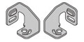
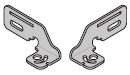
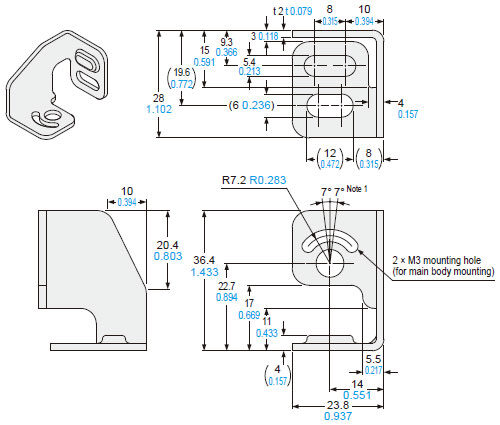
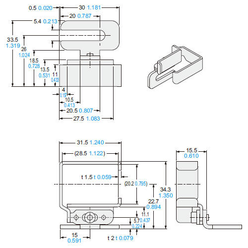
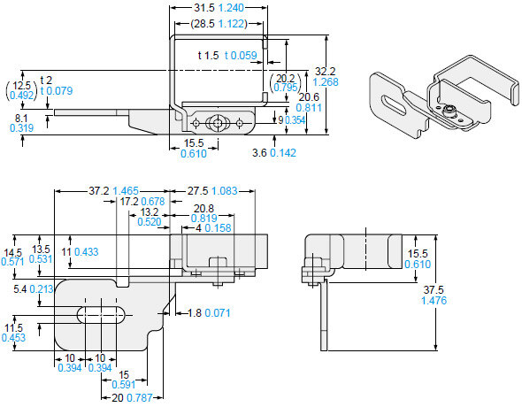
MS-SF4BC-1
Standard mounting bracket (optional)
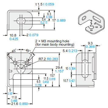
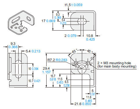
Material: Stainless steel (SUS)
Four brackets (two each R and L type) per set
[Eight M3 (length: 5 mm 0.197 in) hexagon-socket head bolts and four M5 flat washers are attached.]
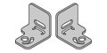
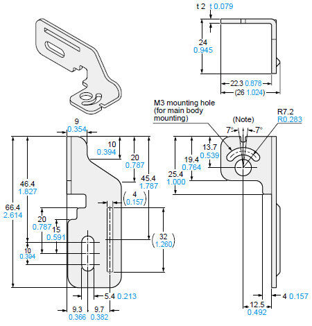
MS-SF4BC-2
Rear utility mounting bracket (optional)
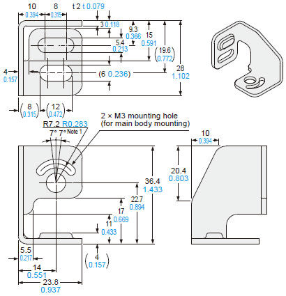
Note: The adjustment range of the safety light curtain angle is up to ±7 degrees.
Material: Stainless steel (SUS)
Four brackets (two each R and L type) per set
[Eight M3 (length: 6 mm 0.236 in) hexagon-socket head bolts and four M5 flat washers are attached.]
MS-SF4BC-3
Side utility mounting bracket (optional)
Material: Stainless steel (SUS)
Four brackets (two each R and L type) per set
[Eight M3 (length: 6 mm 0.236 in) hexagon-socket head bolts and four M5 flat washers are attached.
Note 1: The adjustment range of the safety light curtain angle is up to ±7 degrees.
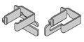
MS-SF4BC-4
Intermediate supporting bracket for utility mounting bracket (optional)
<For rear mounting>
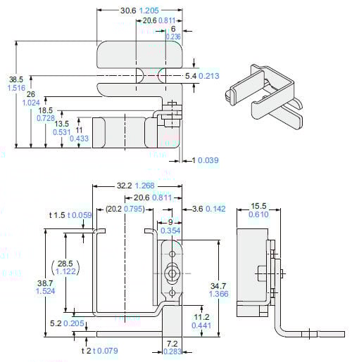
<For side mounting>
Material: Stainless steel (SUS)
Two pcs. M5 flat washers, two pcs. assembled M3 (length: 6 mm 0.236 in) hexagon-socket head bolts for rear mounting, two pcs. attachments for side mounting.
Note:
The numbers of sets required by SF4B-H□C (A-J05) (40 or more beam axes) and SF4B-A□C (A-J05) (20 or more beam axes) are as follows:
SF4B-H40C(A-J05), SF4B-H48C(A-J05), SF4B-H56C(A-J05), SF4B-A20C(A-J05), SF4B-A24C(A-J05), SF4B-A28C(A-J05): 1set
SF4B-H64C(A-J05), SF4B-H72C(A-J05), SF4B-H80C(A-J05), SF4B-A32C(A-J05), SF4B-A36C(A-J05), SF4B-A40C(A-J05): 2sets
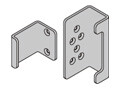
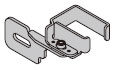
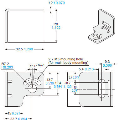
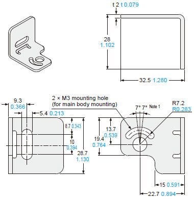
MS-SF4BC-5
Intermediate supporting bracket for standard mounting bracket (optional)
<For rear mounting>
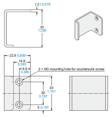
<For side mounting>
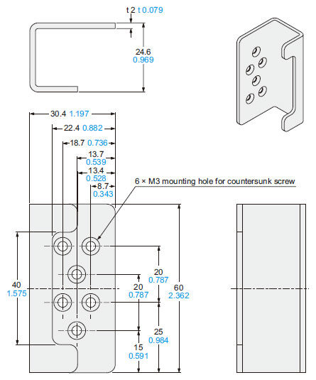
Material: Stainless steel (SUS)
Two pcs. for rear mounting, two pcs. for side mounting
Note:
The numbers of sets required by SF4B-H□C (A-J05) (40 or more beam axes) and SF4B-A□C (A-J05) (20 or more beam axes) are as follows:
SF4B-H40C(A-J05), SF4B-H48C(A-J05), SF4B-H56C(A-J05), SF4B-A20C(A-J05), SF4B-A24C(A-J05), SF4B-A28C(A-J05):1set
SF4B-H64C(A-J05), SF4B-H72C(A-J05), SF4B-H80C(A-J05), SF4B-A32C(A-J05), SF4B-A36C(A-J05), SF4B-A40C(A-J05):2sets
MS-SF4BC-6
Side mounting bracket (optional)

Material: Stainless steel (SUS)
[Eight M3 (length: 6 mm 0.236 in) hexagon-sockethead bolts and four M5 flat washers are attached.]
Four bracket set (two each R and L type)
Note 1: The adjustment range of the safety light curtain angle is up to ±7 degrees.
MS-SF4BC-7
Intermediate supporting bracket for use with side mounting bracket (optional)
Material: Stainless steel (SUS)
[Two pcs. M5 flat washers, two pcs. assembled M3 (length: 6mm 0.236 in hexagon-socket-head bolts for side mounting]2 pcs. per set for side mounting bracket
Note:
The numbers of sets required by SF4B-H□C (A-J05) (40 or more beam axes) and SF4B-A□C (A-J05) (20 or more beam axes) are as follows:
SF4B-H40C(A-J05), SF4B-H48C(A-J05), SF4B-H56C(A-J05), SF4B-A20C(A-J05), SF4B-A24C(A-J05), SF4B-A28C(A-J05):1set
SF4B-H64C(A-J05), SF4B-H72C(A-J05), SF4B-H80C(A-J05), SF4B-A32C(A-J05), SF4B-A36C(A-J05), SF4B-A40C(A-J05):2sets
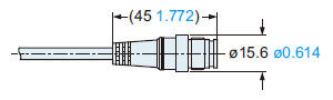
SFB-CC□-MU
Mating cable with connector on one end (optional)
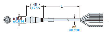
・ Length: L
| Model No. | Length: L |
|---|---|
| SFB-CC3-MU | 3,000 118.110 |
| SFB-CC7-MU | 7,000 275.591 |
| SFB-CC10-MU | 10,000 393.701 |
SFB-CCJ□-MU
Mating cable with connectors on both ends (optional)
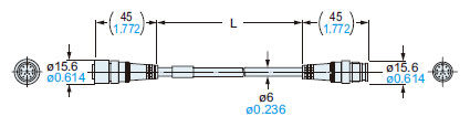
・ Length: L
| Model No. | Length: L |
|---|---|
| SFB-CCJ3D-MU | 3,000 118.110 |
| SFB-CCJ3E-MU | |
| SFB-CCJ10D-MU | 10,000 393.701 |
| SFB-CCJ10E-MU |
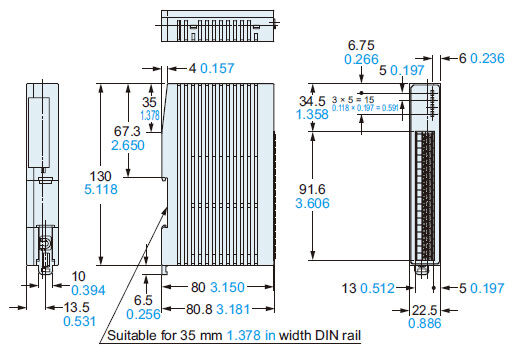
SF-C13
Control unit (optional)
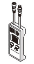
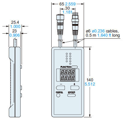
SFB-HC
Handy-controller (optional)
SF-IND-2
Large display unit for light curtain (optional)
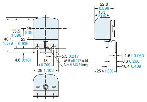
Material:Bracket...Cold rolled carbon steel (SPCC)(Black chromate)Enclosure...POMCover...Polycarbonate
MS-SF4BCH-□
Metal protection case (optional)
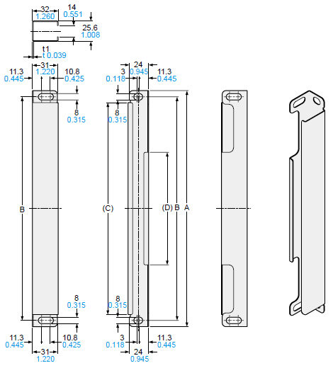
Material: Stainless steel (SUS304)
| Model No. | A | B | C | D |
|---|---|---|---|---|
| MS-SF4BCH-12 | 294.4 11.591 | 279 10.984 | 264.4 10.409 | 140.4 5.528 |
| MS-SF4BCH-16 | 374.4 14.740 | 359 14.134 | 344.4 13.559 | 220.4 8.677 |
| MS-SF4BCH-20 | 454.4 17.890 | 439 17.283 | 424.4 16.709 | 300.4 11.827 |
| MS-SF4BCH-24 | 534.4 21.039 | 519 20.433 | 504.4 19.858 | 380.4 14.976 |
| MS-SF4BCH-28 | 614.4 24.189 | 599 23.583 | 584.4 23.008 | 460.4 18.126 |
| MS-SF4BCH-32 | 694.4 27.339 | 679 26.732 | 664.4 26.157 | 540.4 21.276 |
| MS-SF4BCH-36 | 774.4 30.488 | 759 29.882 | 744.4 29.307 | 620.4 24.425 |
| MS-SF4BCH-40 | 854.4 33.638 | 839 33.031 | 824.4 32.457 | 700.4 27.575 |
| MS-SF4BCH-48 | 1,014.4 39.937 | 999 39.331 | 984.4 38.756 | 860.4 33.874 |
| MS-SF4BCH-56 | 1,174.4 46.236 | 1,159 45.630 | 1,144.4 45.055 | 1,020.4 40.173 |
| MS-SF4BCH-64 | 1,334.4 52.535 | 1,319 51.929 | 1,304.4 51.354 | 1,180.4 46.472 |
| MS-SF4BCH-72 | 1,494.4 58.835 | 1,479 58.228 | 1,464.4 57.654 | 1,340.4 52.772 |
| MS-SF4BCH-80 | 1,654.4 65.134 | 1,639 64.528 | 1,624.4 63.953 | 1,500.4 59.071 |
| MS-SF4BCH-88 | 1,814.4 71.433 | 1,799 70.827 | 1,784.4 70.252 | 1,660.4 65.370 |
| MS-SF4BCH-96 | 1,974.4 77.732 | 1,959 77.126 | 1,944.4 76.551 | 1,820.4 71.669 |
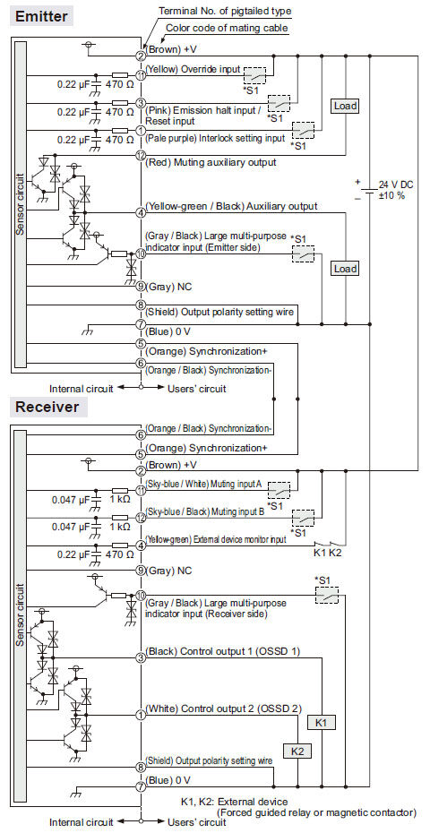
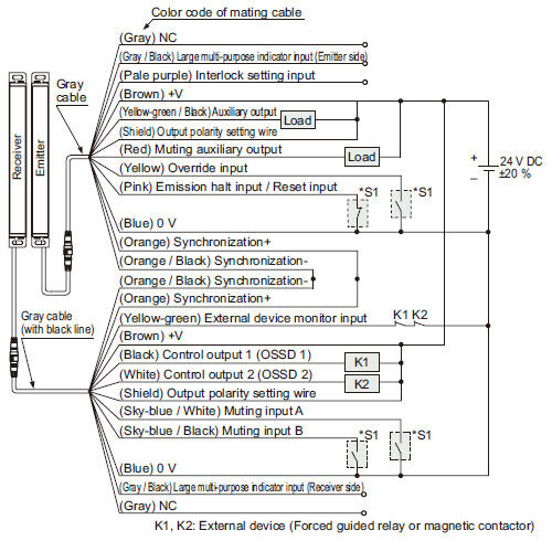
I/O Circuit and Wiring diagrams
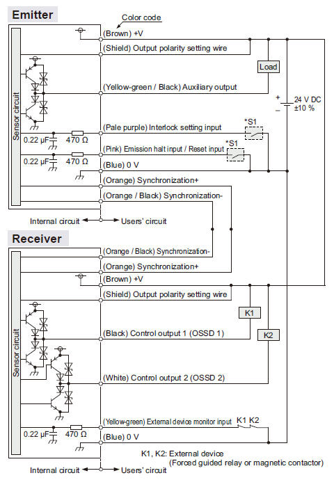
SF4B-□CA-J05
I/O circuit diagrams
<In case of using I/O circuit for PNP output>
* S1
Switch S1
|
Note: Vs is the applying supply voltage.
<In case of using I/O circuit for NPN output>
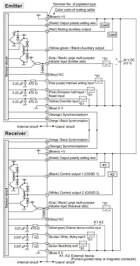
* S1
Switch S1
|
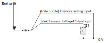
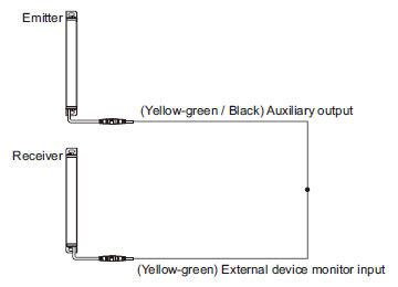
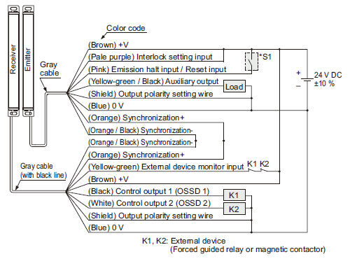
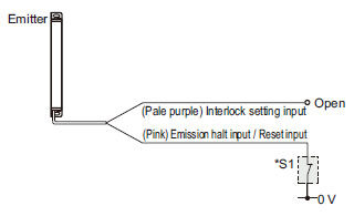
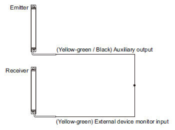
Connection examples
Muting control components: Interlock function "disabled (automatic reset)", external device monitoring function "enabled"
<In case of using I/O circuit for PNP output>
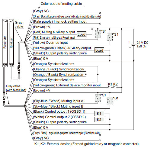
*S1
Switch S1
|
Note: Vs is the applying supply voltage.
The diagram at up shows the configuration when using PNP output, interlock function "disabled (automatic reset)" and external device monitoring function "enabled".
- When the interlock function is set to )"Enable (manual reset),)" the override function cannot be used.
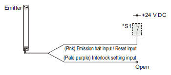
In case of setting the external device monitoring function to "disabled"
<In case of using I/O circuit for NPN output>
*S1
Switch S1
|
The diagram at up shows the configuration when using NPN output, interlock function "disabled (automatic reset)" and external device monitoring function "enabled".
- When the interlock function is set to "Enable (manual reset)," the override function cannot be used.
In case of setting the external device monitoring function to "disabled"
SF4B-□C
I/O circuit diagrams
<In case of using I/O circuit for PNP output>
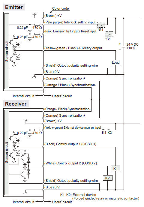
*S1
Switch S1
|
Note: Vs is the applying supply voltage.
<In case of using I/O circuit for NPN output>
*S1
Switch S1
|
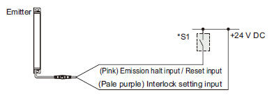
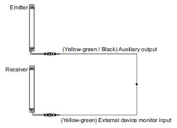
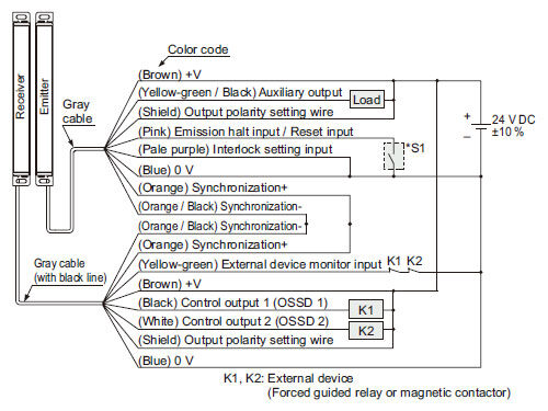
Connection examples
Interlock function "enabled (manual reset)", external device monitoring function "enabled"
<In case of using I/O circuit for PNP output>
*S1
Switch S1
|
Note: Vs is the applying supply voltage.
The diagram at up shows the configuration when using PNP output, interlock function "enabled (manual reset)" and external device monitoring function "enabled".
In case of setting the interlock function to "disabled(automatic reset)"
In case of setting the external device monitoring function to "disabled"

<In case of using I/O circuit for NPN output>
*S1
Switch S1
|
The diagram at up shows the configuration when using NPN output, interlock function "enabled (manual reset") and external device monitoring function "enabled".
In case of setting the external device monitoring function to "disabled"
In case of setting the external device monitoring function to "disabled"
SF-C13
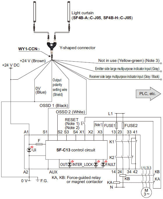
SF4B-□C wiring diagrams (Control Category 4)
- Connect the safety light curtain control outputs OSSD 1 and OSSD 2 to S1 and S2 respectively.
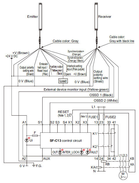
KA, KB:External device(Forced guided relay or magnetic contactor)
Notes:
1) The above diagram is when using manual reset. If automatic reset is used, disconnect the lead from X2 and connect it to X3. In this case, a reset (RESET) button is not needed.
2) Use a momentary-type switch as the reset (RESET) button.
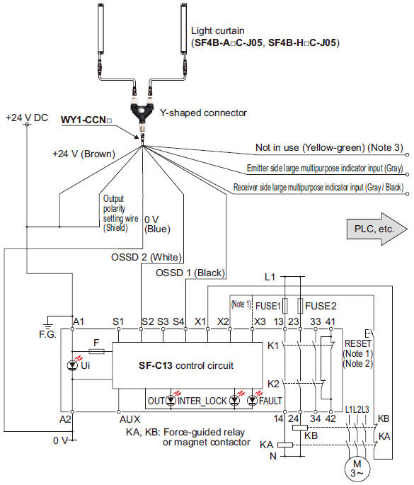
- Connect the safety light curtain control outputs OSSD 1 and OSSD 2 to S4 and S2 respectively and ground the + side.
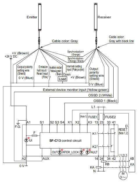
KA, KB:External device(Forced guided relay or magnetic contactor)
Notes:
1) The above diagram is when using manual reset. If automatic reset is used, disconnect the lead from X2 and connect it to X3. In this case, a reset (RESET) button is not needed.Notes:
2) Use a momentary-type switch as the reset (RESET) button.
Wiring diagram: SF-C13 control unit
- Connect the control output 1 (OSSD1) to S1 and the control output 2 (OSSD2) to S2.
Notes:
1) The above design is when using manual reset. If automatic reset is used, disconnect the lead wire from X2 and connect it to X3.In this case, a reset (RESET) button is not needed.
2) Use a momentary-type switch as the reset (RESET) button.3)Unused wires must be insulated.
- Connect the control output 1 (OSSD1) to S4 and the control output 2 (OSSD2) to S2.
Notes:
1) The above design is when using manual reset. If automatic reset is used, disconnect the lead wire from X2 and connect it to X3. In this case, a reset (RESET) button is not needed.
2) Use a momentary-type switch as the reset (RESET) button.3)Unused wires must be insulated.
Terminal arrangement diagram
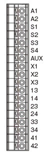
| Terminal | Description |
|---|---|
| A1 | +24 V DC |
| A2 | 0 V |
| S1 to S4 | Safety light curtain control output (OSSD) input terminal |
| AUX | Semiconductor auxiliary output |
| X1 | Reset output terminal |
| X2 | Reset input terminal (Manual) |
| X3 | Reset input terminal (Automatic) |
| 13-14、23-24、33-34 | Safety output (NO contact × 3) |
| 41-42 | Auxiliary output (NC contact × 1) |
When wiring connections to the safety light curtain, you are responsible for providing a terminal block.
- Install this device at a distance of at least A (m) (given below) away from reflective surfaces such as metal walls, floors, ceilings, workpiece, covers, panels or glass surfaces.
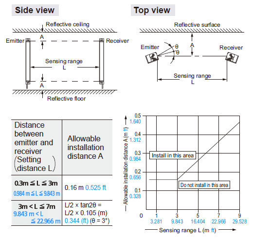
Note: The effective aperture angle for this device is ±2.5° or less (when L > 3 m9.843 ft) as required by IEC 61496-2, ANSI/UL 61496-2. However, install this device away from reflective surfaces considering an effective aperture angle of ±3° to take care of beam misalignment, etc. during installation.