Basic Information
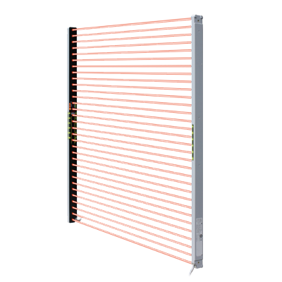
Introducing Type 2 Ultra-slim Light Curtains!
Featuring easy installation and reduced wiring


CE : Machinery Directive, EMC Directive
UKCA : Machinery Regulations, EMC Regulations
UL, CSA : Certified by TÜV SÜD America Inc.

Features
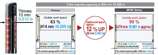
Slim size for efficient applications
Available work space is expanded from the previous model, and productivity is improved.
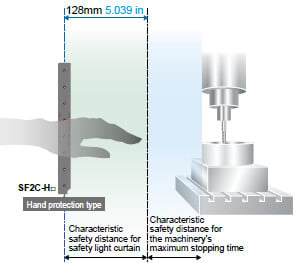
Simple safety distance calculations
Recalculation of the safety distance is unnecessary for each time safety light curtain length is changed.
Safety Distance SF2C-H□ : 128 mm 5.039 in (Calculation based on ISO 13855)
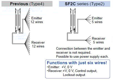
Dramatically less wiring work with optical synchronization
Safety light curtain wiring consists of just five wires each for the emitter and receiver, allowing you to easily implement safety measures in about the same amount of time as with an area sensor with using optical synchronization.
Beam axis alignment made easy
The emitter has an effective aperture angle of ±5° or less for an operating range of 3 m 9.843 ft. Compared to Type 4 safety light curtains (which have an effective aperture angle of ±2.5° or less), the SF2C series is easy to align and install.
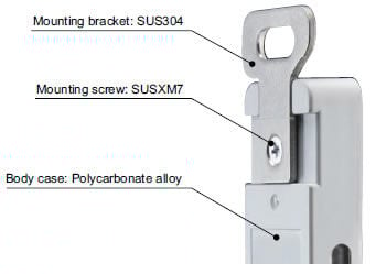
Easy installation
The standard mounting bracket is already mounted for easy installation.
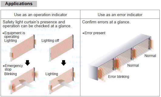
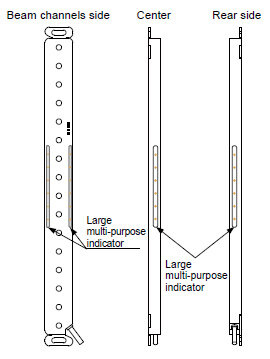
Can be used in a variety of applications for simplified equipment [Large multi-purpose indicator]
The bright LED indicators located in the center of both sides of each safety light curtain can be light on / blink in orange with external inputs. There is no need for setting up a separate indicator, so that equipment is consolidated.
Light weight!
The SF2C series is made of resin and is approximately 45% lighter than the conventional aluminum case type*.
Its lightweight body eases the burden on the mounting surface of the equipment and contributes to overall reduced weight during equipment transportation or overseas shipment.
*Except the cable part
Protection structure IP67
An IP67 (IEC) rating is achieved even in an ultra-slim resin body using a laser welding method.
A fast response time for all models
SF2C-H□: 20 ms
The SF2C series reduces the safety distance as well as the calculation work required for the safety distance among models with different beam channels.
Material suitable for manufacturing a secondary battery
SF2C body is made of resin and the mounting bracket is made of Stainless Steel (SUS), so materials used are limited. Suitable for manufacturing secondary batteries or for food production equipment.
Order guide
Product configuration
*1 The SF2C series does not incorporate the external device monitoring function.
*2 Requires a safety circuit architecture that complies with the desired control category implemented using either an SF-C13 Control Unit, a safety relay, or other equipment.
[1] Safety light curtains
Hand protection type
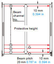
Min. sensing object ø25 mm ø0.984 in (20 mm 0.787 in beam pitch)
| Appearance | Operating range (Note 1) | Model No. (Note 2) | No. of beam Channels | Protective height (mm in) | |
|---|---|---|---|---|---|
| PNP output type | NPN output type | ||||
| 0.1 to 3m 0.328 to 9.843 in | SF2C-H8-P | SF2C-H8-N | 8 | 160 6.299 |
| SF2C-H12-P | SF2C-H12-N | 12 | 240 9.449 | ||
| SF2C-H16-P | SF2C-H16-N | 16 | 320 12.598 | ||
| SF2C-H20-P | SF2C-H20-N | 20 | 400 15.748 | ||
| SF2C-H24-P | SF2C-H24-N | 24 | 480 18.898 | ||
| SF2C-H28-P | SF2C-H28-N | 28 | 560 22.047 | ||
| SF2C-H32-P | SF2C-H32-N | 32 | 640 25.197 | ||
Notes:
1) The operating range is the possible setting distance between the emitter and the receiver.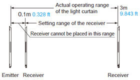
2) The model No. with suffix "E" shown on the label affixed to the product is the emitter, "D" shown on the label is the receiver.
Spare parts (Accessories for safety light curtain)
| Designation | Model No. | Description |
|---|---|---|
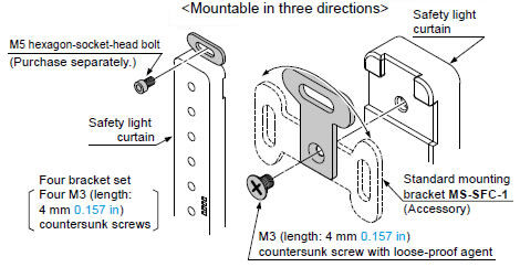
| Standard mounting bracket | MS-SFC-1 | Allows the safety light curtain to be mounted at the rear with one M5 hexagon-socket-head bolt. Mounting direction of the bracket can be selected between vertical or horizontal (no dead zone). (4 pcs. per set for emitter and receiver) (Note) |
| Test rod ø25 | SF4C-TR25 | Min. sensing object for regular checking (ø25 mm ø0.984 in) |
Note : The body of the safety light curtain is made of resin, so please take into account the expansion and contraction of the longitudinal dimension.
When machining mounting holes, please check the actual product.
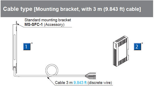
Standard mounting bracket
MS-SFC-1
[2] Control unit
| Designation | Appearance | Model No. | Description |
|---|---|---|---|
| Slim type control unit |
| SF-C13 | Use a discrete wire cable to connect to the safety light curtain. Relay output. Compatible with up to control category 4 (control category 2 when used together with the SF2C series). |
Option
Mounting bracket
| Designation | Model No. | Description |
|---|---|---|
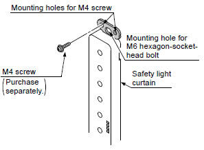
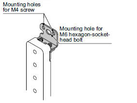
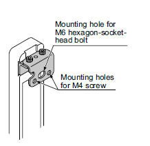
| NA2-N compatible mounting bracket | MS-SFC-2 | Used when changing over area sensor NA2-N series to the SF2C series. The mounting holes of NA2-N series can continue to be used. Center mounting by a M6 hexagon-socket-head bolt is also possible. (4 pcs. per set for emitter and receiver) (Note) |
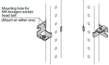
| Versatile bracket | MS-SFC-3 | Two ways of mounting are possible. (1)Rear mounting which enables beam adjustment (2)Dead zoneless center mounting on aluminum frame (4 pcs. per set for emitter and receiver) (Note) |
| Intermediate supporting bracket for versatile bracket | MS-SFC-4 | Used to support the safety light curtain in the middle. Be sure to purchase it when using MS-SFC-3 on SF2C-H28-P, SF2C-H28-N, SF2C-H32-P, SF2C-H32-N. (2 pcs. per set for emitter and receiver) (Note) |
Note : The body of the safety light curtain is made of resin, so please take into account the expansion and contraction of the longitudinal dimension.
When machining mounting holes, please check the actual product.
NA2-N compatible mounting bracket
MS-SFC-2
Versatile bracket
MS-SFC-3
<Rear mounting>
<Dead zoneless mounting>
Intermediate supporting bracket for versatile bracket
MS-SFC-4
Metal protection case

(Excluding MS-SFCH-8)

| Applicable beam channels | Metal protection case (2 pcs. per set for emitter and receiver) |
|---|---|
| SF2C-H□ | Model No. |
| 8 | MS-SFCH-8 |
| 12 | MS-SFCH-12 |
| 16 | MS-SFCH-16 |
| 20 | MS-SFCH-20 |
| 24 | MS-SFCH-24 |
| 28 | MS-SFCH-28 |
| 32 | MS-SFCH-32 |
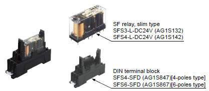
Recommended safety relay
SF relay, slim type
SF series
Note:Please contact our sales office for details on the recommended products.
| Type | With LED indicator | |
|---|---|---|
| Model No. | SFS3-L-DC24V | SFS4-L-DC24V |
| Part No. | AG1S132 | AG1S142 |
| Contact arrangement | 3a1b | 4a2b |
| Rated nominal switching capacity | 6A/250V AC、6A/30V DC | |
| Min. switching capacity | 1mA/5V DC | |
| Coil rating | 15mA/24V DC | 20.8mA/24V DC |
| Rated power consumption | 360mW | 500mW |
| Operation time | 20ms or less | |
| Release time | 20ms or less | |
| Ambient temperature | -40 to +85 ℃ -40 to + 185 ℉ (Humidity: 5 to 85 % RH) | |
| Applicable certifications | UL/c-UL, TÜV, Korea S-mark | |
Dimensions
- Unit: mm in
SF2C-H□
Safety light curtain
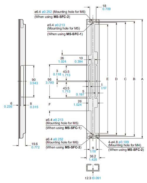
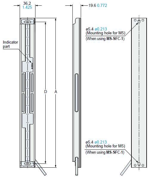
Mounting bracket assembly dimensions
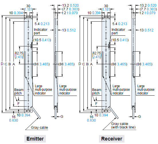
Mounting drawing for the safety light curtains using the standard mounting brackets MS-SFC-1 (accessory).
<Center mounting>
<Dead zoneless mounting>
| Model No. | A | B | C | D | E |
|---|---|---|---|---|---|
| SF2C-H8-□ | 140 5.512 | 160 6.299 | 172 6.772 | 184 7.244 | 130 5.118 |
| SF2C-H12-□ | 220 8.661 | 240 9.449 | 252 9.921 | 264 10.394 | 210 8.268 |
| SF2C-H16-□ | 300 11.811 | 320 12.598 | 332 13.071 | 344 13.543 | 290 11.417 |
| SF2C-H20-□ | 380 14.961 | 400 15.748 | 412 16.220 | 424 16.693 | 370 14.567 |
| SF2C-H24-□ | 460 18.110 | 480 18.898 | 492 19.370 | 504 19.842 | 450 17.717 |
| SF2C-H28-□ | 540 21.260 | 560 22.047 | 572 22.520 | 584 22.992 | 530 20.866 |
| SF2C-H32-□ | 620 24.409 | 640 25.197 | 652 25.669 | 664 26.142 | 610 24.016 |
| Model No. | F | G |
|---|---|---|
| SF2C-H□ | 20 0.787 | ø3.7 ø0.146 |
Note:
1) The body of the safety light curtain is made of resin, so please take into account the expansion and contraction of the longitudinal dimension.
When machining mounting holes, please check the actual product.
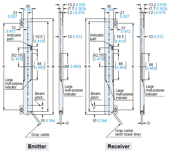
Mounting drawing for the safety light curtains using the versatile brackets MS-SFC-3 (optional) and intermediate supporting bracket for versatile brackets MS-SFC-4 (optional).
<Rear mounting>
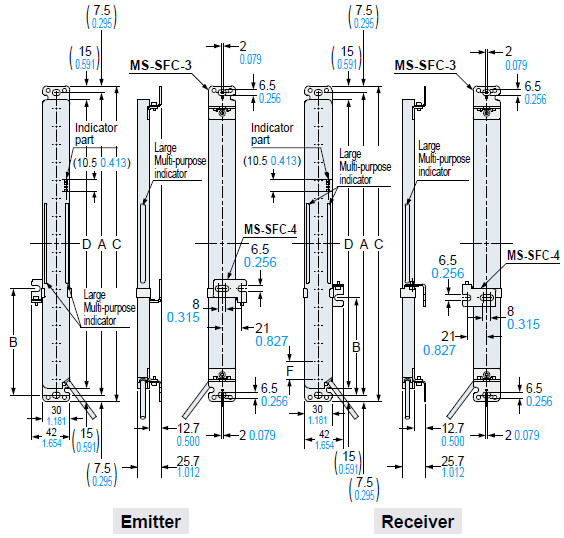
<Dead zoneless mounting>
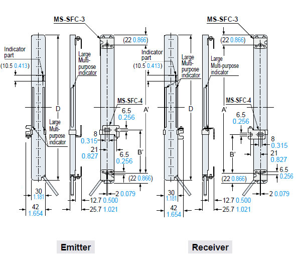
| Model No. | Inter mediate supporting bracket | A | A' | B | B' | C | D |
|---|---|---|---|---|---|---|---|
| SF2C-H8-□ | - | 175 6.890 | 116 4.567 | - | - | 190 7.480 | 160 6.299 |
| SF2C-H12-□ | - | 255 10.039 | 196 7.717 | - | - | 270 10.630 | 240 9.449 |
| SF2C-H16-□ | - | 335 13.189 | 276 10.866 | - | - | 350 13.780 | 320 12.598 |
| SF2C-H20-□ | - | 415 16.339 | 356 14.016 | - | - | 430 16.929 | 400 15.748 |
| SF2C-H24-□ | - | 495 19.488 | 436 17.165 | - | - | 510 20.079 | 480 18.898 |
| SF2C-H28-□ | ○ | 575 22.638 | 516 20.315 | 238 to 338 9.370 to 13.307 | 209 to 309 8.228 to 12.165 | 590 23.228 | 560 22.047 |
| SF2C-H32-□ | ○ | 655 25.787 | 596 23.465 | 278 to 378 10.945 to 14.882 | 249 to 349 9.803 to 13.740 | 670 26.378 | 640 25.197 |
Note:
1) Be sure to mount MS-SFC-4 when using SF2C-H28-□, SF2C-H32-□.
2) The body of the safety light curtain is made of resin, so please take into account the expansion and contraction of the longitudinal dimension.
When machining mounting holes, please check the actual product.
MS-SFC-1
Standard mounting bracket (Accessory)
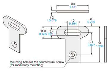
Material: Stainless steel (SUS304)
Net weight: 32 g approx. (4 pcs.)
Gross weight: 35 g appox.
Four bracket set[Four M3 (length 4 mm 0.157 in) countersunk screws are attached.]
MS-SFC-2
NA2-N compatible mounting bracket (Optional)
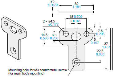
Material: Stainless steel (SUS304)
Net weight: 36 g approx. (4 pcs.)
Gross weight: 40 g appox.
Four bracket set[Four M3 (length 4 mm 0.157 in) countersunk screws are attached.]
MS-SFC-3
Versatile bracket (Optional)
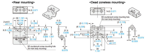
Material: Stainless steel (SUS304)
Net weight: 75 g approx. (4 pcs.)
Gross weight: 90 g appox.
Four bracket set[Four M3 (length 4 mm 0.157 in) countersunk screws are attached.]
MS-SFC-4
Intermediate supporting bracket for versatile bracket (Optional)
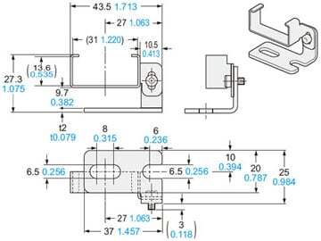
Material: Stainless steel (SUS304)
Net weight: 40 g approx. (2 pcs.)
Gross weight: 60 g appox.Two bracket set
MS-SFCH-□
Metal protection case (Optional)
Material: Aluminum
| Model No. | A | B | C | D | E | F | Net weight (2 pcs.) |
|---|---|---|---|---|---|---|---|
| MS-SFCH-8 | 190 7.480 | 180 7.087 | 175 6.890 | 172 6.772 | 162 6.378 | 26 1.024 | 160 g approx. |
| MS-SFCH-12 | 270 10.630 | 260 10.236 | 255 10.039 | 252 9.921 | 242 9.528 | 35 1.378 | 240 g approx. |
| MS-SFCH-16 | 350 13.780 | 340 13.386 | 335 13.189 | 332 13.071 | 322 12.677 | 35 1.378 | 340 g approx. |
| MS-SFCH-20 | 430 16.929 | 420 16.535 | 415 16.339 | 412 16.220 | 402 15.827 | 35 1.378 | 420 g approx. |
| MS-SFCH-24 | 510 20.079 | 500 19.685 | 495 19.488 | 492 19.370 | 482 18.976 | 35 1.378 | 520 g approx. |
| MS-SFCH-28 | 590 23.228 | 580 22.835 | 575 22.638 | 572 22.520 | 562 22.126 | 35 1.378 | 600 g approx. |
| MS-SFCH-32 | 670 26.378 | 660 25.984 | 655 25.787 | 652 25.669 | 642 25.276 | 35 1.378 | 700 g approx. |
Assembly dimensions
Mounting drawing for the safety light curtains using the metal protection case (MS-SFCH-□).
| Model No. | A | D |
|---|---|---|
| MS-SFCH-8 | 190 7.480 | 172 6.772 |
| MS-SFCH-12 | 270 10.630 | 252 9.921 |
| MS-SFCH-16 | 350 13.780 | 332 13.071 |
| MS-SFCH-20 | 430 16.929 | 412 16.220 |
| MS-SFCH-24 | 510 20.079 | 492 19.370 |
| MS-SFCH-28 | 590 23.228 | 572 22.520 |
| MS-SFCH-32 | 670 26.378 | 652 25.669 |
I/O Circuit and Wiring diagrams
PNP output type
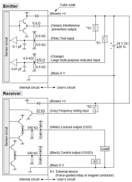
・S1,S2
Switch S1
- Test input / Large multi-purpose indicator input
ON : Vs –2.5 V to Vs
OFF : Open
Switch S2
- Frequency setting input
Frequency 1 setting: Open
Frequency 2 setting: +V
Notes:
1) If the large multi-purpose indicator input wiring (Orange) is connected to +V, the orange LED lights on. When they are disconnected, the orange LED lights off.
2) Vs is the applying supply voltage.
NPN output type
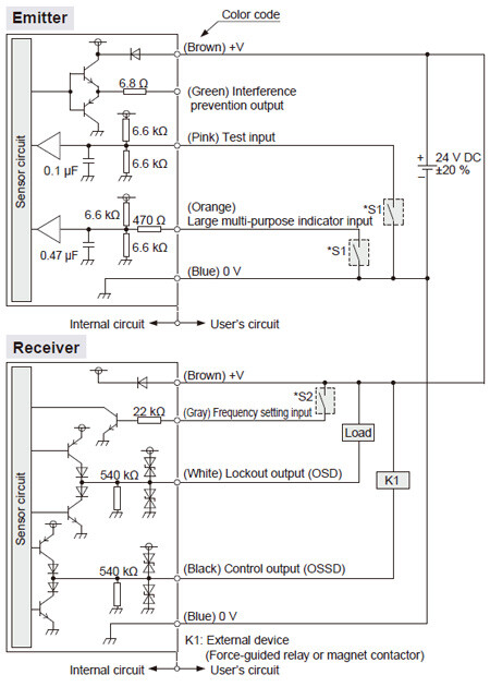
・S1,S2
Switch S1
- Test input / Large multi-purpose indicator input
ON : 0 to +2.5 V
OFF : Open
Switch S2
- Frequency setting input
Frequency 1 setting: Open
Frequency 2 setting: +V
Note: If the large multi-purpose indicator input wiring (Orange) is connected to 0V, the orange LED lights on. When they are disconnected, the orange LED lights off.
Connection example
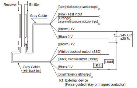
Basic wiring: Min. operation only
This is the general configuration using one set of the emitter and receiver facing each other. The control output (OSSD) turns OFF if the light is interrupted, while it automatically turns ON if receive the light.
<PNP output type SF2C-H□-P>
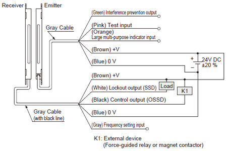
<NPN output type SF2C-H□-N>
Wiring in case of using test input / large multi-purpose indicator / interference prevention functions
<PNP output type SF2C-H□-P>
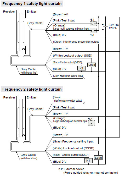
・S1
- Switch S1
ON: Vs –2.5 V to Vs
OFF: Open
<Frequency setting input>
- Frequency 1 setting: Open
Frequency 2 setting: +V
Notes:
1) If the large multi-purpose indicator input wiring (Orange) is connected to +V, the orange LED lights on. When they are disconnected, the orange LED lights off.
2) Vs is the applying supply voltage.
<NPN output type SF2C-H□-N>
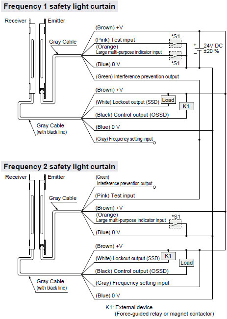
・S1
- Switch S1
ON: 0 to +2.5 V
OFF: Open
<Frequency setting input>
- Frequency 1 setting: Open
Frequency 2 setting: +V
Note: If the large multi-purpose indicator input wiring (Orange) is connected to 0V, the orange LED lights on. When they are disconnected, the orange LED lights off.
Control unit SF-C13 wiring diagram (Control category 2)
PNP output type: Min. operation only
Connect the safety light curtain control output OSSD to S1 and make a short-circuit between S2 and S3.
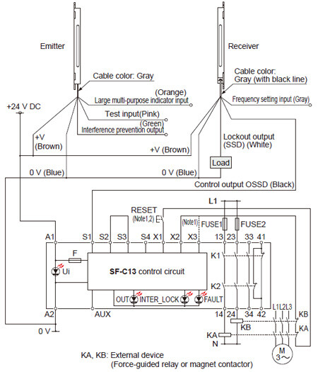
Notes :
1) The diagram is when using manual reset. If automatic reset is used, disconnect the lead from X2 and connect it to X3. In this case, a reset (RESET) button is not needed.
2) Use a momentary-type switch as the reset (RESET) button.
NPN output type: Min. operation only
Connect the safety light curtain control output OSSD to S4 and make a short-circuit between S2 and S3.
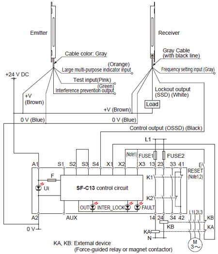
Notes:
1) The left diagram is when using manual reset. If automatic reset is used, disconnect the lead from X2 and connect it to X3. In this case, a reset (RESET) button is not needed.
2) Use a momentary-type switch as the reset (RESET) button.
Terminal arrangement diagram
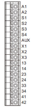
| Terminal | Function |
|---|---|
| A1 | +24 V DC |
| A2 | 0 V |
| S1 to S4 | Safety light curtain control output (OSSD) input terminal |
| AUX | Semiconductor auxiliary output |
| X1 | Reset output terminal |
| X2 | Reset input terminal (Manual) |
| X3 | Reset input terminal (Automatic) |
| 13-14, 23-24, 33-34 | Safety output (NO contact × 3) |
| 41-42 | Auxiliary output (NC contact × 1) |
A terminal block is required for wiring of safety light curtain side.
・This website is a guide to select a suitable product. Be sure to read instruction manual attached to the product prior to its use.
・Both emitter and receiver are combined adjusted on factory setting, please apply both emitter and receiver with the same serial No. The serial No. is indicated on the plates of both emitter and receiver.
(Indicated under the model No.)
- Make sure to carry out the test run before regular operation.
- Do not install this device with a machine whose operation cannot be stopped immediately in the middle of an operation cycle by an emergency stop equipment.
Others
- This device has been developed / produced for industrial use only.
- Do not use this product with mobile equipment such as an automated guided vehicle (AGV).
- Do not use during the initial transient time (2 sec.) after the power supply is switched on.
- Avoid dust, dirt and steam.
- Take care that the safety light curtain does not come in direct contact with water, oil, grease, or organic solvents, such as, thinner, etc.
- Take care that the safety light curtain is not directly exposed to fluorescent light from a rapid-starter lamp or a high frequency lighting device, as it may affect the sensing performance.
- The body of the safety light curtain is made of resin, so please take into account the expansion and contraction of the longitudinal dimension.
When machining mounting holes, please check the actual product.
Part description and function
<Indicator part>

Common for emitter and receiver
| Description | Function |
|---|---|
| Large multi-purpose indicator (Orange) | Lights up when input for the large multi-purpose indicator is valid. Turns OFF when input for the large multi-purpose indicator is invalid. |
| Frequency setting indicator (Orange) [FREQ] | Turns OFF when Frequency 1 is set. Lights up when Frequency 2 is set. |
| Fault indicator (Yellow) [FAULT] | Turns OFF during normal operation. Lights up or blinks when fault occurs in the device. |
Emitter
| Description | Function |
|---|---|
| Operation indicator (Green) [POWER] | Lights up when device operation is as follows. Turns OFF when test input is valid. |
| Test indicator (Red) [TEST] | Lights up when test input is valid. Turns OFF when test input is invalid. |
Receiver
| Description | Function |
|---|---|
| OSSD indicator (Red / green) [OSSD] | When control output (OSSD) is OFF: lights up in red When control output (OSSD) is ON: lights up in green |
| Unstable light reception indicator (Orange) [STB] | Turns OFF when stable light is received (the percentage of light received is more than 150%). [Control output (OSSD) ON] Lights up when unstable light is received (the percentage of light received is between 100% and 150%). [Control output (OSSD) ON] Turns OFF when light is blocked (the percentage of light received is less than 100%). (Note 1) [Control output (OSSD) OFF] |
Notes:
1) Besides, ‘when light is blocked’ refers to the status that there exists any object blocking light in the sensing area.
2) The description given in [ ] is marked on the device.