Basic Information
Creating safety circuits is easier than ever!


UL, CSA : Certified by TÜV SÜD America Inc.


- The control category differs depending on the configuration and wiring of the external circuit.
Features
Add new features and make it even more convenient!
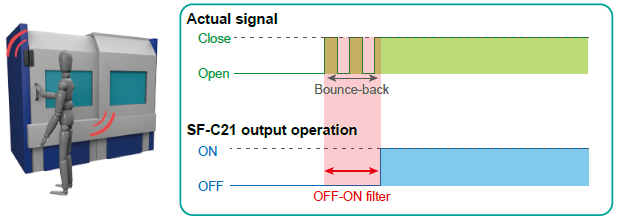
■Input filter time setting
OFF-ON filter
Avoid unstable operation caused by vibrations and/or bounce-back when closing guards.
ON-OFF filter
Avoid unstable operation due to momentary blockages of a safety light curtain by operational vibrations, bugs, dust, and other causes.
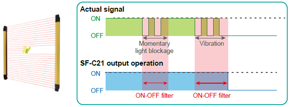
When using the ON-OFF filter, note that the OFF response time will increase to the sum of 10 ms and the ON-OFF filter set time.
■Exit-only muting function
We’ve added an exit-only muting function as an option for the parallel muting function. This functionality is ideal for use in environments where muting input cannot be added to exits such as openings through which workpieces are ejected.

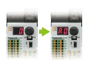
■Logic display edit
This function lets you assign alphabetical letters as labels when configuring custom logic settings, enabling easy identification of the configuration in use on the unit itself when using multiple custom logic components on multiple safety control units.
■Other convenient functions
Extend allowable duration time for sequential muting
The allowable duration time for muting input used with sequential muting control, which was previously limited to a maximum of 10 sec., can now be set to up to 288,000 sec. An unlimited setting is also available.
Windows 11*1 support
Configure settings easily with the Configurator SF-C software tool.
*1: Ver.2.03 or later
*2: Windows is either registered trademarks or trademarks of Microsoft Corporation in the United States and/or other countries.
Easy 1
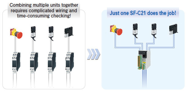
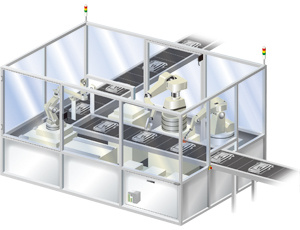
Finding space to install and wire is easy
One SF-C21 can do the work of four safety relay units.
Simple to wire the units in the control panel!!
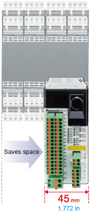
Small, so the unit can be installed in a narrow space
Compact with a height 97 mm 3.819 in × width 45 mm 1.772 in.
It's easy to find installation space for the SF-C21 unit.
Easy to monitor status with a generalpurpose PLC
Four auxiliary outputs (PNP semiconductor output) are provided.
Using RS-485 communications (MODBUS RTU), various general-purpose control units (PLC, HMI, etc.) can monitor the SF-C21 information such as the status, the selected logic, and any error status.
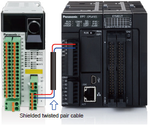
Note: Communication information can not be used for safety control.
Long-life semiconductor output (PNP) adopted for control output and auxiliary output
Easy 2
Absolutely no programming skills required.
Operation is easy - just select a preset logic
Simply turn a switch to set
Eight preset logics, safety-certified and compatible up to control category 4 PLe, can be selected by simply turning the rotary switch.
*The logic customized by user can be stored in the logic No. 0.
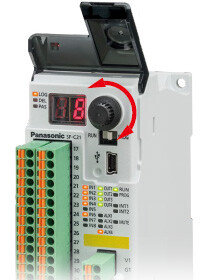
Refer to " 8 preset logics"
Easy to set the "OFF delay"
The OFF delay time can be easily set by simply turning the rotary switch to any one of patterns.
| Pattern No. | 0 | 1 | 2 | 3 | 4 | 5 | 6 | 7 | 8 | 9 |
|---|---|---|---|---|---|---|---|---|---|---|
| OFF delay time (sec.) | 0 | 0.1 | 0.5 | 1 | 2 | 5 | 10 | 15 | 30 | 60 |
* The OFF delay time applies to control output 2. In case of setting the OFF delay time to control output 1, the "Configurator SF-C" software is needed.
Password protection prevents inadvertent logic changes
Easy 3
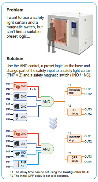
Application-based customization is easy
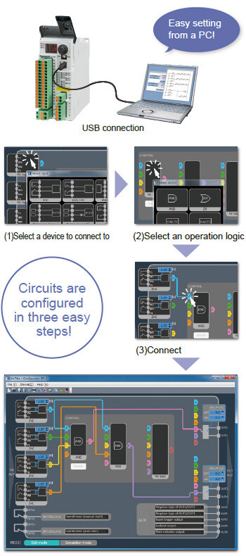
Easy to create a reliable safety circuit Use our "Configurator SF-C" software to build your own safety circuits of connected devices, control logic, output modes, etc. No programming skills required!
Customized logics are safety-certified too!!
All possible logic combinations created with the "Configurator SF-C" software are already safety-certified by the certification bodies. The software also has a "simulation mode" to test if the prepared logic and safety circuit operates as intended. If the logic is not complete, the software will block its transfer to the SF-C21 unit.
Note:
Please read the instruction manual in advance when selecting or creating logics, and verify whether the combination of connecting devices and logics complies with each machine safety standard.
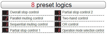
8 preset logics compatible up to control category 4, PLe standards
Note:
Please make sure that the combination of logics and input devices complies with each machine safety standard.
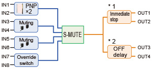
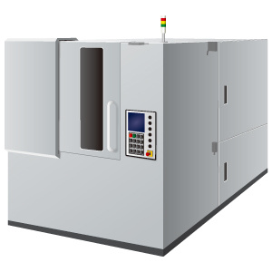
Logic No.1:Overall stop control
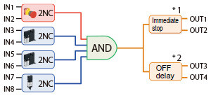
When any connected input becomes OFF, the entire control output will be OFF.
*1 The delay time can be set using the Configurator SF-C.
*2 The initial OFF delay is set to 0 seconds.
Logic No.2:Parallel muting control
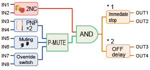
When the muting input becomes ON, the safety light curtain will be temporarily disabled.
*1 The delay time can be set using the Configurator SF-C.
*2 The initial OFF delay is set to 0 seconds.
Logic No.3:Sequential muting control
Only when the muting input becomes ON following a predefined sequence, the safety light curtain will
be temporarily disabled.
*1 The delay time can be set using the Configurator SF-C.
*2 The initial OFF delay is set to 0 seconds.
Logic No.4:Partial stop control 1
When the emergency stop input is OFF, the entire control output will be OFF. When any other input is OFF, its corresponding control output will be OFF.
*1 The delay time can be set using the Configurator SF-C.
*2 The initial OFF delay is set to 0 seconds.
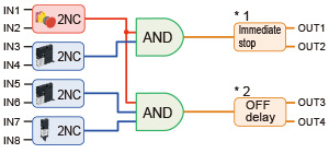
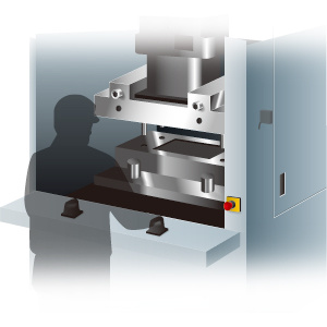
Logic No.5:Partial stop control 2
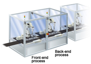
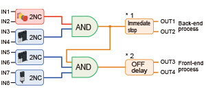
When the emergency stop input or the input from the back-end process becomes OFF, the entire control output will be OFF. When the input from the front-end process becomes OFF, only its corresponding control output will be OFF.
*1 The delay time can be set using the Configurator SF-C.
*2 The initial OFF delay is set to 0 seconds.
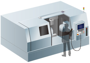
Logic No.6:Two-hand control
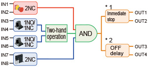
This control is applied when a two-hand operation switch is used for control.Only when both switches of the two-hand operation switch are operated within 0.5 sec., control output will be ON.
*1 The delay time can be set using the Configurator SF-C.
*2 The initial OFF delay is set to 0 seconds.
Logic No.7:OR control
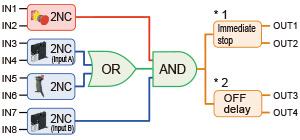
Even when the guard (input A) is OFF, if the enabling switch is ON the control output will be ON. If either the emergency switch or input B becomes OFF, the entire control output will be OFF regardless of the status of the input A and emergency switch.
*1 The delay time can be set using the Configurator SF-C.
*2 The initial OFF delay is set to 0 seconds.
Logic No.8:Operation mode selection control
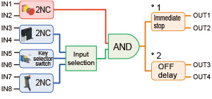
Only when mode selection using the key selector is followed by the enabling switch being turned ON, the control output will be ON regardless of the open / close status of the guard.
Note that if the emergency stop switch is OFF, the entire control output will be OFF.
*1 The delay time can be set using the Configurator SF-C.
*2 The initial OFF delay is set to 0 seconds.
Order guide
| Product name | Appearance | Model No. | Number of input points | Number of output points | ||
|---|---|---|---|---|---|---|
| Safety input | Reset / EDM input | Control output | Auxiliary output | |||
| Safety control unit |
| SF-C21 | 2×4 | 2 | 2×2 | 4 |
Specifications
| Product name | Safety control unit | |
|---|---|---|
| Model No. | SF-C21 | |
| Applicable standards | Safety | IEC 61508-1 to 3, EN 61508-1 to 3(SIL3), ISO 13849-1:2015 (Category 4, PLe), IEC 61131-2, IEC 61010-2-201, IEC 62061(SILCL3), UL 61010-1, UL 61010-2-201, UL 1998, KS C 9811 : 2019(EN 55011), KS C 9610-6-2 : 2019(EN 61000-6-2) |
| EMC | IEC 61000-6-2, IEC 61326-3-1, EN 55011 | |
| Related standards | IEC 60947-1, IEC 60947-5-1, IEC 60947-5-2, IEC 60947-5-5 IEC 60947-5-8, IEC 61496-1, IEC TS 62046, ISO 13851 | |
| Applicable regulations and certifications | CE Marking (Machinery Directive, EMC Directive, RoHS Directive), UKCA Marking [Supply of Machinery (Safety) Regulations, EMC Regulations, RoHS Regulations), TÜV SÜD certification, TÜV SÜD certification (USA, Canada), Korea's Radio Waves Act conformity registration | |
| Supply voltage (Note 1, 2) | Power supply for internal | 24 V DC +10-15% Ripple P-P10 % or less |
| Power supply for external | 24 V DC +10-15% Ripple P-P10 % or less | |
| Current consumption (Note 1, 2) | Power supply for internal | 200 mA or less |
| Power supply for external | 100 mA or less | |
| Safety input (IN1 to IN8) | 2×4 inputs, Rated voltage: Same as the voltage of the power supply for internal | |
| ON level / OFF level | Input voltage: 18 V, Input current: 3.5 mA / Input voltage: 5 V, Input current: 1.0 mA | |
| Rated input current / Input impedance | 5 mA approx. / 4.7 K Ω approx. | |
| Duration of detectable ON state | 10 ms or more | |
| Duration of undetectable OFF state | 0.7 ms or less | |
| Control output (OUT1 to OUT4) | PNP open-collector transistor with 2 outputs × 2 • Maximum source current: 300 mA / output • Applied voltage: Same as the voltage of the power supply for external • Residual voltage: 2.5 V or less • Leakage current: 100 μA or less (Including power supply OFF condition) | |
| Output mode | True : ON, False : OFF | |
| ON delay function / OFF delay function | Incorporated / Incorporated | |
| Short-circuit protection / Response time | Incorporated / OFF response: 10 ms or less, ON response: 100 ms or less | |
| Auxiliary output (AUX1 to AUX4) (Non-safety output) | PNP open-collector transistor with 1 output × 4 • Maximum source current: 60 mA / output • Applied voltage: Same as the voltage of the power supply for external • Residual voltage: 2.5 V or less • Leakage current: 100 μA or less (Including power supply OFF condition) | |
| Output mode (Factory defaults) | AUX1: Negative logic of OUT1 / OUT2 (ON when OUT1 / OUT2 is OFF) AUX2: Negative logic of OUT3 / OUT4 (ON when OUT3 / OUT4 is OFF) AUX3: Reset trigger output (ON under reset release wait condition) AUX4: Lockout output (OFF when lockout) | |
| Output mode (Any of the auxiliary outputs can be customized using the software tool) | Negative logic of OUT1 / OUT2(ON when OUT1 / OUT2 is OFF) Negative logic of OUT3 / OUT4 (ON when OUT3 / OUT4 is OFF) Positive logic of OUT1 / OUT2 (ON when OUT1 / OUT2 is ON) Positive logic of OUT3 / OUT4(ON when OUT3 / OUT4 is ON) Outputs A, B, C, and D of diagnosis results of input blocks (ON when logic is true) Outputs E, F, and G of internal logic circuit diagnostic results (ON when logic is true) Reset trigger output (ON under reset release wait condition) Lockout output (OFF when lockout) Muting indicator output (ON when muting / override) Monitor output in response to IN1 to IN8 (ON when input) No output (normally OFF) | |
| Short-circuit protection / Response time | Incorporated / 10 ms or less | |
| Muting indicator output | Semiconductor photo MOS relay output × 1 • Maximum load current: 60 mA • Supply voltage: Same as the voltage of the power supply for internal • Residual voltage: 2.5 V or less • Leakage current: 100 μA or less (Including power supply OFF condition) | |
| Output mode | ON when muting / override | |
| Short-circuit protection / Response time | Incorporated / 10 ms or less | |
| Interlock function / Lockout release function | Incorporated / Incorporated | |
| External device monitor function | Incorporated | |
| Communication function (MODBUS RTU) | Interface: RS-485 Protocol: MODBUS RTU Maximum transmission distance: 100 m 328.084 ft Maximum number of units that can be connected: 8 units (slaves) | |
| Logic selection function | No.0: Customization control No.1: Overall stop control No.2: Parallel muting control No.3: Sequential muting control No.4: Partial stop control 1 No.5: Partial stop control 2 No.6: Two-hand control No.7: OR control No.8: Operation mode selection control | |
| Logic setting function | Input mode, control mode, output mode, reset mode, auxiliary output mode | |
| Pollution degree / Excess voltage category | 2 / II | |
| Usable altitude (Note 3) | 2,000 m 6561.680 ft or less | |
| Startup time after power on | 2 sec. or less | |
| PFHD(Note 4) / MTTFD (Note 4) | 9.73 × 10⁻¹⁰ / 100 years or more | |
| Protection | IP20 (IEC) (must be installed in a control panel with protection IP54 or higher) | |
| Ambient temperature | -10 to +55 ℃ +14 to +131 ℉ (No dew condensation or icing allowed), Storage: -25 to +60 ℃ -13 to +140 ℉ | |
| Ambient humidity | 30 to 85% RH, Storage: 30 to 85% RH | |
| Dielectric strength voltage / Insulation resistance | 1,000 V AC for one min. / 20 MΩ, or more, with 500 V DC megger. (All inputs connected together - USB port, all inputs connected together - RS-485 port, USB port - RS-485 port, between all supply terminals connected together and enclosure, all outputs connected together - all input connected together, all outputs connected together - USB port, all outputs connected together - RS-485 port) | |
| Vibration resistance | 5 to 8.4 Hz frequency, 3.5 mm 0.138 in half amplitude, 8.4 to 150 Hz frequency, Max. acceleration 9.8 m/s2 (1 G), in X, Y and Z directions for two hours each (IEC / EN 60068-2-6) | |
| Shock resistance | 147 m/s2 (15 G) 11 ms in X, Y and Z directions three times each (IEC / EN 60068-2-27) | |
| Connection method | Input / output and power supply: Detachable spring cage terminal blocks, RS-485: Detachable spring-cage terminal block, USB: Mini-B male | |
| Maximum cable length | 100 m 328.084 ft or less | |
| Material | Main unit enclosure: Polycarbonate / ABS polymer alloy, Enclosure: Polycarbonate | |
| Weight | Net weight: 190 g approx., Gross weight: 320 g approx. | |
Notes:
1) "Power supply for internal" is the power supply for safety input. "Power supply for external" is the power supply for control output / auxiliary output. The power supplies for internal and external are insulated.
2) The power supply unit connected to this device must satisfy the conditions below.
• Output voltage within 20.4 V to 26.4 V DC (Ripple P-P: 10% or less.)
• Power supply unit SELV (safety extra low voltage) / PELV (protected extra low voltage) conforming to the EMC Directive and Low-voltage Directive (In case CE Marking conformity is required.)
• Power supply unit conforming to the Low-voltage Directive and with an output of 100 VA or less
• Power supply unit with an output holding time of 20 ms or more.
• Power supply unit SELV (safety extra low voltage) / PELV (protected extra low voltage) conforming to the EMC Regulations and Low-voltage Regulations (In case UKCA Marking conformity is required.)
• Power supply unit corresponding to CLASS 2 (In case C-TÜV US Listing Mark conformity is required.)
3) Do not use or store this device in a pressurized environment beyond the atmospheric pressure at sea level.
4) PFHD: Probability of dangerous failure per hour, MTTFD: Mean time to dangerous failure (in years)
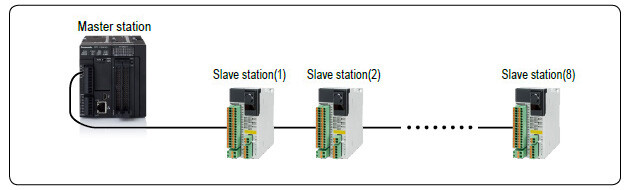
RS-485 (MODBUS RTU) SPECIFICATIONS
With built-in RS-485, SF-C21 can read out its status, error history, etc. to an external device such as a general-purpose PLC, using the MODBUS RTU protocol.
Up to eight SF-C21 units can communicate with the external device as the master station.
The communication preference of MODBUS RTU is set with the DIP switch on the main unit or the software tool "Configurator SF-C".
Types of data that can be read out
• Status (HIGH, LOW) of safety input and reset / EDM output
• Status (HIGH, LOW) of control output, auxiliary output, and muting indicator output
• Lockout history
• Logic No. change history
■ MODBUS RTU SPECIFICATIONS
| Interface | RS-485 |
|---|---|
| Max. transmission distance | 100m 328.084 ft |
| Communication address | 1-247 |
| Data length | 8 bits(fixed) |
| Parity bit | Without / Odd / Even |
| Stop bit | 1 bit / 2 bits |
| Communication speed | 9,600 bps 19,200 bps 38,400 bps 57,600 bps 115,200 bps |
■ MAIN BODY DIP SWITCH SPECIFICATIONS
| Switch NO. | Setting item | Input status | |
|---|---|---|---|
| OFF | ON | ||
| 1 | Communication preference settings | DIP switches take precedence | Software tools take precedence |
| 2 | Parity bit presence | With | Without |
| 3 | Parity bit type | Odd | Even |
| 4 | Stop bit | 1 | 2 |
| 5 | Communication address 1 | SW5:OFF, SW6:OFF | |
| Communication address 2 | SW5:ON, SW6:OFF | ||
| 6 | Communication address 3 | SW5:OFF, SW6:ON | |
| Communication address 4 | SW5:ON, SW6:ON | ||
| 7 | Communication speed | 9,600 bps | 19,200 bps |
| 8 | Reserved | - | - |
| 9 | Reserved | - | - |
| 10 | Reserved | - | - |
Note: The SF-C21 cannot be controlled by an external device.
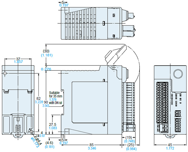
Dimensions
- Unit: mm in
Software

Enable flexible customization
The software provides highly flexible customization. You can create a logic of your own, change the input device types based on the preset logics, or customize logic data uploading from the SF-C21 main unit. Changing the auxiliary output settings, as well as setting the ON delay / OFF delay time and muting state holding time are all very easy as well. Created logics can be stored in a PC for convenient future use.
Settable items
- Input device selection
- Logic selection (up to three layers)
- Auxiliary output settings [Linkage to control output (positive logic and negative logic), monitor output of safety input, reset trigger output, lockout output, etc.]
- OFF delay time setting (0.0 to 60.0 sec, in 1/10 sec.)
- ON delay time setting [1 to 5,940 sec (99 min), in sec.]
- Muting valid time setting [1 to 5,940 sec (99 min), in sec.] or no limit
- Override valid time setting (1 to 600 sec, in sec.)
- RS-485 (MODBUS RTU) communication settings, etc.
Multilingual compatibility
The Configurator SF-C supports seven languages: Japanese,
English, Chinese, Spanish, French, Italian and Portuguese.
Our products support users around the world by fulfilling their
diverse needs, such as the empowerment of local staff and
implementation of local safety schemes.
Versatile functions
Input filter time setting
・OFF-ON filter: Avoid unstable operation caused by vibrations and/or bounce-back when closing guards.
・ON-OFF filter: Avoid unstable operation due to momentary blockages of a safety light curtain by operational vibrations, bugs, dust, and other causes.
Status monitoring function
The status of input and output devices connected to SF-C21 can be monitored in real time through USB.
Simulation function
Whether the logic created by the user operates as intended can be verified via a software tool.
Incomplete transfer blocking function
The transfer of incomplete logics to SF-C21 will be blocked and prevent potential hazards
Note: Please read the instruction manual in advance when customizing logics, and verify whether the combination of connecting devices and logics complies with each machine safety standard.
Software are available for download.
I/O Circuit and Wiring diagrams
TERMINAL ARRANGEMENT DIAGRAM
[Terminal block for I/O 1]
| Terminal No. | Terminal name | Function |
|---|---|---|
| 1 | IN1 | Safety input 1 |
| 2 | T1 | Safety input 1 / test output |
| 3 | IN2 | Safety input 2 |
| 4 | T2 | Safety input 2 / test output |
| 5 | IN3 | Safety input 3 |
| 6 | T3 | Safety input 3 / test output |
| 7 | IN4 | Safety input 4 |
| 8 | T4 | Safety input 4 / test output |
| 9 | MUTE1 | Muting indicator output 1_1 |
| 10 | NC | Not connected |
| 11 | INT11 | Reset input 1 / test output |
| 12 | INT12 | Reset input 1 |
| 13 | AUX1 | Auxiliary output 1 |
| 14 | AUX2 | Auxiliary output 2 |
| 15 | AUX3 | Auxiliary output 3 |
| 16 | AUX4 | Auxiliary output 4 |
[Terminal block for I/O 2]
| Terminal No. | Terminal name | Function |
|---|---|---|
| 17 | IN5 | Safety input 5 |
| 18 | T5 | Safety input 5 / test output |
| 19 | IN6 | Safety input 6 |
| 20 | T6 | Safety input 6 / test output |
| 21 | IN7 | Safety input 7 |
| 22 | T7 | Safety input 7 / test output |
| 23 | IN8 | Safety input 8 |
| 24 | T8 | Safety input 8 / test output |
| 25 | MUTE2 | Muting indicator output 1_2 |
| 26 | NC | Not connected |
| 27 | INT21 | Reset input 2 / test output |
| 28 | INT22 | Reset input 2 |
| 29 | OUT1 | Control output 1 |
| 30 | OUT2 | |
| 31 | OUT3 | Control output 2 |
| 32 | OUT4 |
[Power supply for external]
| Terminal No. | Terminal name | Function |
|---|---|---|
| V2 | V2 | Power supply for control output / power supply for auxiliary output (+V) |
| G2 | G2 | Power supply for control output / power supply for auxiliary output (0V) |
[Power supply for internal]
| Terminal No. | Terminal name | Function |
|---|---|---|
| V1 | V1 | Power supply for safety input (+V) |
| G1 | G1 | Power supply for safety input (0V) |
[RS-485]
| Terminal No. | Terminal name | Function |
|---|---|---|
| + | + | Transmission line(+) |
| - | - | Transmission line(-) |
| + | + | Transmission line(+) |
| - | - | Transmission line(-) |
| E | E | Terminal station setting |
Note: For an input device requiring a separate power supply, such as a safety light curtain, use the same power supply as the power supply for internal.
Connection examples
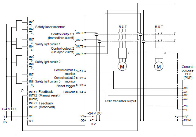
Logic No.1 Overall stop control (Manual reset mode)
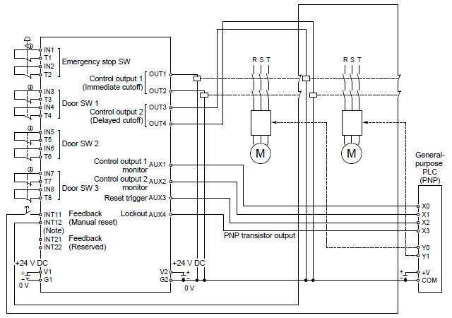
Note:Select contacts that can support the micro load of 6 mA at 24 V DC as the reset switch and contacts used for INT11 / INT12 (INT21 / INT22).
Logic No.1 Overall stop control (Auto reset mode)
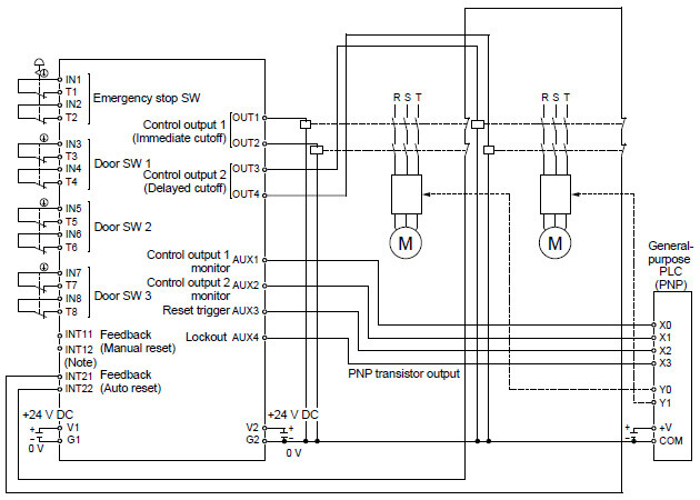
Note:Select contacts that can support the micro load of 6 mA at 24 V DC as the reset switch and contacts used for INT11 / INT12 (INT21 / INT22).
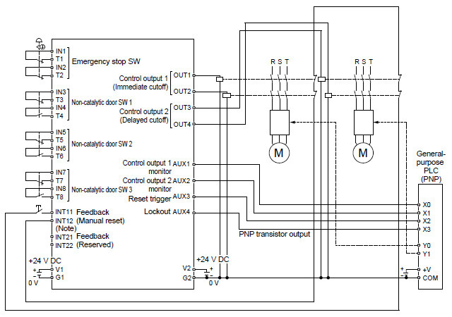
Logic No.4 Partial stop control 1 (Manual reset mode)
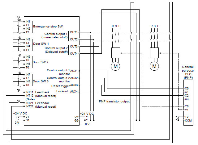
Note:Select contacts that can support the micro load of 6 mA at 24 V DC as the reset switch and contacts used for INT11 / INT12 (INT21 / INT22).
Customization example, based on logic No.4 Partial stop control 1 (Auto reset mode)
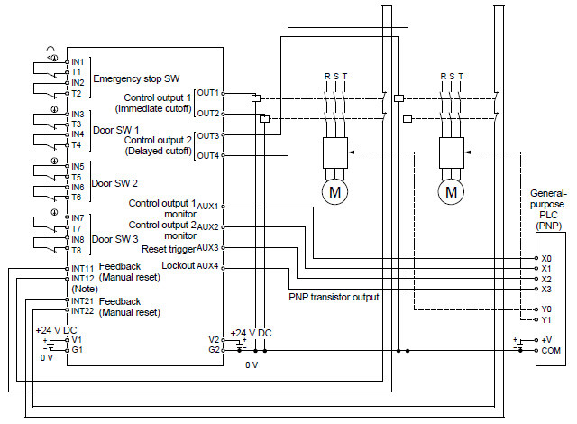
Note:Select contacts that can support the micro load of 6 mA at 24 V DC as the reset switch and contacts used for INT11 / INT12 (INT21 / INT22).
Customization example, based on logic No.1 Overall stop control (Manual reset, when all input devices are changed to PNP input × 2)
Note:Select contacts that can support the micro load of 6 mA at 24 V DC as the reset switch and contacts used for INT11 / INT12 (INT21 / INT22).
Customization example, based on logic No.1 Overall stop control (Manual reset, when input 3 to 8 are changed to devices with 1NC / 1NO)
Note:Select contacts that can support the micro load of 6 mA at 24 V DC as the reset switch and contacts used for INT11 / INT12 (INT21 / INT22).
- This device has been developed / produced for industrial use only.
- Some features have been addded from production in November 2015.
>>See more details here
In order to use the additional features fully, you need the Ver. 2.00 or later of SF-C21 (main unit) and Configrator SF-C.
[1] The SF-C21 software version can be confirmed in the following way.
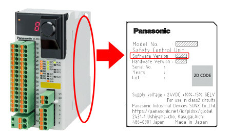
*Please check the software version is 2.00 or later, is applied on the label on a right side panel.
(Note):
Unable to accept firmware update request for shipped elder versions SF-C21 caused by the limitation of the safety certificates.
[2]
The software version of Configrator SF-C can be confirmed from "Version" in "Help" menu. If you use the software version lower than Ver.2.00, please download the latest version from our website and install it.
>>Click here to download Configrator SF-C.
Environment
- Do not use a mobile phone or a radio phone near this device.
- This device starts the performance after 2 seconds from the power ON. Have the control system started to function with this timing.
- Do not install this device in the following environments.
1) The device is exposed to direct sunlight.
2) Dew condensation may occur due to sudden changes in temperature.
3) The ambient air contains corrosive or flammable gas.
4) There is a high level of dust, metallic dust, or salt content.
5) The device may be exposed to organic solvents such as benzene, thinner, or alcohol and/or strong alkaline substances such as ammonia or caustic soda, or any such substances exist in the ambient air.
6) The device may be directly exposed to vibration or impact or to water drops.
7) The device may be exposed to interference from nearby high-voltage lines, high-voltage equipment, power wires, motor equipment, an amateur radio station or other transmitter, or a device with large switching surges (the device must be placed at a distance of 100 mm 3.937 in or greater from any interference sources).