Discontinued Products

MS-GXL8-4 (Sensor mounting bracket for GXL-8FU, GXL-8HU type)
1 pc. each of M3(length: 12 mm0.472 in) truss head screw, nut, spring washer and plain washer is attached.
MS-A15F (Aluminum sheet for GXL-15FLU type)
MS-A15H (Aluminum sheet for GXL-15HLU, GXL-15HL type)
MS-GXL15 (Sensor mounting bracket for GXL-15 type)
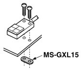
Screws are not supplied.
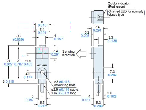
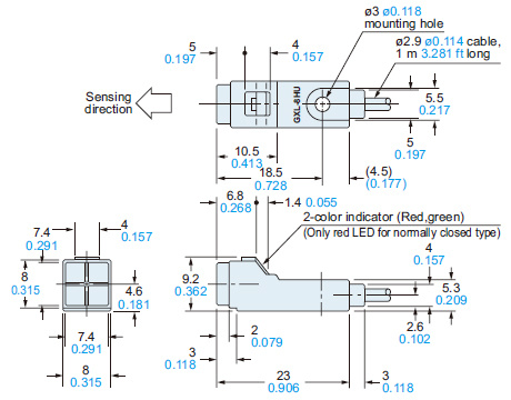
Dimensions
Unit: mm in
GXL-8FU type
Sensor
GXL-8HU type
Sensor
GXL-15F type
Sensor

Note:Normally closed type have an operation indicator (red) instead of the 2-color indicator.
GXL-15H type
Sensor

Note:Normally closed type have an operation indicator (red) instead of the 2-color indicator.
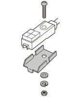
MS-GXL8-4
Sensor mounting bracket for GXL-8FU / GXL-8HU type (Accessory)

Material:Stainless steel (SUS304)
1 pc. each of M3 (length 12 mm 0.472 in) truss head screw, nut, spring washer and plain washer is attached.
MS-GXL15
Sensor mounting bracket for GXL-15 type (Optional)

Material:Cold rolled carbon steel (SPCC)
MS-GXL15-2
Sensor mounting bracket for GXL-15F type (Optional)

Material:
Bracket ... Stainless steel (SUS304)
Fixed rubber ... FKM (Fluorine rubber)
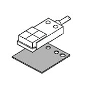
MS-A15F
MS-A15H
Aluminum sheet (Accessory for GXL-15FLU / GXL-15HLU type)

I/O Circuit and Wiring diagrams
GXL-8 type
I/O circuit diagram

Symbols・・・
ZD: Surge absorption zener diode
Tr : PNP output transistor
Note:The maximum load current varies depending on the ambient temperature.

Wiring diagram

Conditions for the load
- The load should not be actuated by the leakage current (0.8 mA) in the OFF state.
- The load should be actuated by (supply voltage – 3 V) in the ON state.
- The current in the ON state should be between 3 to 70 mA DC.
[In case the current is less than 3 mA, connect a bleeder resistance in parallel to the load so that a current of 3 mA, or more, flows.]
GXL-15 type
I/O circuit diagram

Symbols・・・
ZD: Surge absorption zener diode
Tr : PNP output transistor
Note: The maximum load current varies depending on the ambient temperature.

Wiring diagram

Conditions for the load
- The load should not be actuated by the leakage current (0.8 mA) in the OFF state.
- The load should be actuated by (supply voltage – 3 V) in the ON state.
- The current in the ON state should be between 3 to 100 mA DC.
[In case the current is less than 3 mA, connect a bleeder resistance in parallel to the load so that a current of 3 mA, or more, flows.]


As the sensing object size becomes smaller than the standard size (iron sheet 15 × 15 × t 1 mm 0.591 × 0.591 × t 0.039 in), the sensing range shortens as shown in the left figures.


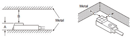
Influence of surrounding metal
- When there is a metal near the sensor, keep the minimum separation distance specified below.
Front sensing type
| GXL-8F type | GXL-15FU type | GXL-15FLU type | |
|---|---|---|---|
| A | 7 mm 0.276 in | 8 mm 0.315 in | 8 mm 0.315 in (Note) |
| B | 8 mm 0.315 in | 20 mm 0.787 in | 30 mm 1.181 in |
| C | 3 mm 0.118 in | 7 mm 0.276 in | 10 mm 0.394 in |
Note: The GXL-15FLU type should be mounted on an insulator or a non-magnetic body.
To mount it on a magnetic body, such as iron, use the enclosed aluminum sheet.
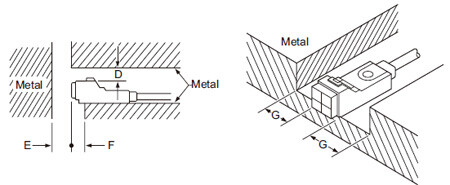
Top sensing type
| GXL-8H type | GXL-15HU type | GXL-15HLU type | |
|---|---|---|---|
| D | 4 mm 0.157 in | 6 mm 0.236 in | 12 mm 0.472 in |
| E | 10 mm 0.394 in | 20 mm 0.787 in | 30 mm 1.181 in |
| F | 3 mm 0.118 in | 0 mm 0 in | 10 mm 0.394 in (Note) |
| G | 3 mm 0.118 in | 3 mm 0.118 in | 10 mm 0.394 in |
Note: When GXL-15HLU type is mounted on an insulator or a non-magnetic body, or seated on the enclosed aluminum sheet, the distance "F" can be zero.
Mutual interference prevention
- When two or more sensors are installed in parallel or face to face, keep the minimum separation distance specified below to avoid mutual interference.


| H | J | ||
|---|---|---|---|
| GXL-8 type | Between "I" type and non "I" type | 0 mm (Note 2) | 15 mm 0.591 in |
| Between two "I" types or two non "I" types | 18 mm 0.709 in | 30 mm 1.181 in | |
| GXL-15FU GXL-15HU type | Between "I" type and non "I" type | 0 mm (Note 2) | 25 mm 0.984 in |
| Between two "I" types or two non "I" types | 30 mm 1.181 in | 60 mm 2.362 in | |
| GXL-15FLU GXL-15HLU type | Between "I" type and non "I" type | 0 mm (Note 2) | 25 mm 0.984 in |
| Between two "I" types or two non "I" types | 75 mm 2.953 in | 90 mm 3.543 in | |
Notes:
1) "I" in the model No. specifies the different frequency type.
2) Close mounting is possible for up to two sensors.
When mounting three sensors or more at an equal spacing, align the model with "I" and the model without "I" alternately.
The minimum value of dimension "H" should be as given below.
GXL-8 type: 5 mm 0.1975 in,
GXL-15FU/15HU type: 7.5 mm 0.295 in,
GXL-15FLU/15HLU type: 30 mm 1.181 in
Sensing range
- The sensing range is specified for the standard sensing object.
With a non-ferrous metal, the sensing range is obtained by multiplying with the correction coefficient specified below. Further, the sensing range also changes if the sensing object is smaller than the standard sensing object or if the sensing object is plated.
Correction coefficient
| GXL-8 type | GXL-15FU type | GXL-15HU GXL-15FLU GXL-15HLU type | |
|---|---|---|---|
| Iron | 1 | 1 | 1 |
| Stainless steel (SUS304) | 0.82 approx. | 0.74 approx. | 0.75 approx. |
| Brass | 0.59 approx. | 0.53 approx. | 0.53 approx. |
| Aluminum | 0.57 approx. | 0.52 approx. | 0.51 approx. |
Others
- Do not use during the initial transient time (50 ms) after the power supply is switched on.
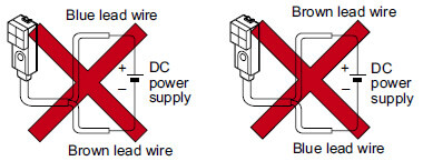
Wiring
- The sensor must be connected to a power supply via a load. If the sensor is connected to a power supply without a load, the short-circuit protection makes the sensor inoperable. (The output stays in the OFF state and the indicator does not light up.) In this case, rectify by connecting the power supply via a load. Now, the sensor becomes operable. Further, take care that if the power supply is connected with reverse polarity without a load, the sensor will get damaged.
- For series connection (AND circuit) or parallel connection (OR circuit) of sensors, take care of the following.
![マイクロ近接センサ[アンプ内蔵] GXL](https://ap.industry.panasonic.com/hubfs/pid-corp/products/fasys/sensor/proximity/gxl/attention/images/pic08.jpg)
- The residual voltage of the sensor is 3 V. Before connecting a relay at the load, take care of its actuation voltage. (Some 12 V relays may not be usable.)
![マイクロ近接センサ[アンプ内蔵] GXL](https://ap.industry.panasonic.com/hubfs/pid-corp/products/fasys/sensor/proximity/gxl/attention/images/pic09.jpg)
Use conditions to comply with CE Marking
- Following work must be done in case of using this product as a CE Marking (European standard EMC Directive)conforming product.
Ensure that the shield is connected to 0 V.
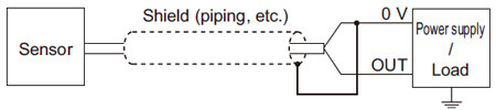
Note:The shield (piping, etc.) must be insulated.