Basic Information
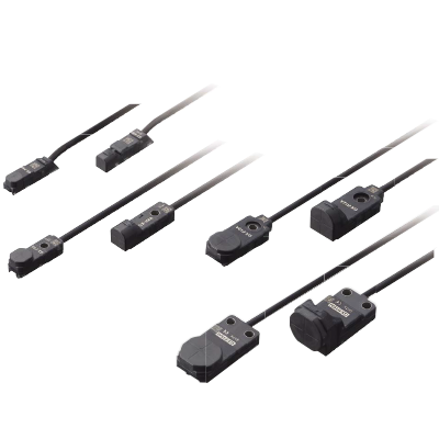
Industry No. 1* in stable sensing
*Based on research conducted by Panasonic Industry as of among equivalent rectangular inductive sensors as of June 2024.


Variation at the maximum operation distance is within ±8 %
Thorough adjustment and control of sensing sensitivity greatly reduces individual sensor differences and variations.
The work of adjusting sensor positions when using multiple sensors and when sensors have been replaced is much easier.
Example: GX-□8
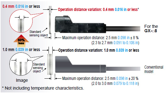
Temperature characteristics vary within ±8 %
Components such as the sensor coil and core and product design have been totally revised to provide excellent temperature characteristics.
Stable sensing can be obtained regardless of the time of day or the yearly season.

10 times the durability! (Compared to conventional models)
The new integrated construction method used provides shock resistance of 10,000 m/s2 (approx. 1,000 G in X, Y and Z directions for three times each), and vibration resistance clears durability tests of between 10 and 500 Hz (3 mm 0.118 in double amplitude in X, Y and Z directions for 2 hours each). In addition, resistance to impulse noise is approx. three times greater than for conventional models.


Highly resistant to water or oil! IP68G* protective construction
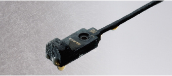
Indicators are easy to see over a wide field of view
A prism with a wide field of view has been developed. This has greatly improved the visibility of the operation indicators.

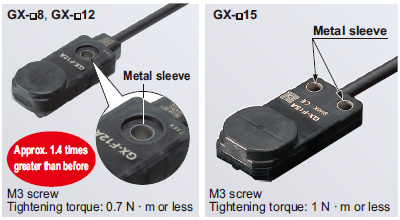
Tightening strength increased with no damage! (excluding GX-□6)
A metal sleeve has been inserted.
It prevents the sensor from being damaged by tightening too much.
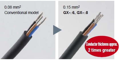
Conductor thickness doubled to make wiring much easier! (GX-□6/GX-□8 only)
The conductor's thickness was doubled for the GX-□6/GX-□8. This makes it easier to handle and perform crimping work on the cables. In addition, the tensile strength of the crimping area has become higher.


Order guide
GX-6 type
| Type | Appearance (mm in) | Sensing range (Note 1) | Model No. (Note 2) | Output | Output operation | |
|---|---|---|---|---|---|---|
| NPN output | Front sensing |
| Maximum operation distance: 1.6 mm 0.063 in Stable sensing range : 0 to 1.3 mm 0 to 0.051 in | GX-F6A | NPN open-collector transistor | Normally open |
| GX-F6AI | ||||||
| GX-F6B | Normally closed | |||||
| GX-F6BI | ||||||
| Top sensing |
| GX-H6A | Normally open | |||
| GX-H6AI | ||||||
| GX-H6B | Normally closed | |||||
| GX-H6BI | ||||||
| PNP output | Front sensing |
| GX-F6A-P | PNP open-collector transistor | Normally open | |
| GX-F6AI-P | ||||||
| GX-F6B-P | Normally closed | |||||
| GX-F6BI-P | ||||||
| Top sensing |
| GX-H6A-P | Normally open | |||
| GX-H6AI-P | ||||||
| GX-H6B-P | Normally closed | |||||
| GX-H6BI-P | ||||||
Note 1 : The maximum operation distance stands for the maximum distance for which the sensor can detect the standard sensing object.
The stable sensing range stands for the sensing range for which the sensor can stably detect the standard sensing object even if there is an ambient temperature drift and/or supply voltage fluctuation.
Note 2 : " I " in the model No. indicates a different frequency type.
GX-8 type
| Type | Appearance (mm in) | Sensing range (Note 1) | Model No. (Note 2) | Output | Output operation | |
|---|---|---|---|---|---|---|
| NPN output | Front sensing |
| Maximum operation distance: 2.5 mm 0.098 in Stable sensing range : 0 to 2.1 mm 0 to 0.083 in | GX-F8A | NPN open-collector transistor | Normally open |
| GX-F8AI | ||||||
| GX-F8B | Normally closed | |||||
| GX-F8BI | ||||||
| Top sensing |
| GX-H8A | Normally open | |||
| GX-H8AI | ||||||
| GX-H8B | Normally closed | |||||
| GX-H8BI | ||||||
| PNP output | Front sensing |
| GX-F8A-P | PNP open-collector transistor | Normally open | |
| GX-F8AI-P | ||||||
| GX-F8B-P | Normally closed | |||||
| GX-F8BI-P | ||||||
| Top sensing |
| GX-H8A-P | Normally open | |||
| GX-H8AI-P | ||||||
| GX-H8B-P | Normally closed | |||||
| GX-H8BI-P | ||||||
Note 1 : The maximum operation distance stands for the maximum distance for which the sensor can detect the standard sensing object.
The stable sensing range stands for the sensing range for which the sensor can stably detect the standard sensing object even if there is an ambient temperature drift and/or supply voltage fluctuation.
Note 2 : " I " in the model No. indicates a different frequency type.
GX-12 type
| Type | Appearance (mm in) | Sensing range (Note 1) | Model No. (Note 2) | Output | Output operation | |
|---|---|---|---|---|---|---|
| NPN output | Front sensing |
| Maximum operation distance: 4.0 mm 0.157 in Stable sensing range : 0 to 3.3 mm 0 to 0.130 in | GX-F12A | NPN open-collector transistor | Normally open |
| GX-F12AI | ||||||
| GX-F12B | Normally closed | |||||
| GX-F12BI | ||||||
| Top sensing |
| GX-H12A | Normally open | |||
| GX-H12AI | ||||||
| GX-H12B | Normally closed | |||||
| GX-H12BI | ||||||
| PNP output | Front sensing |
| GX-F12A-P | PNP open-collector transistor | Normally open | |
| GX-F12AI-P | ||||||
| GX-F12B-P | Normally closed | |||||
| GX-F12BI-P | ||||||
| Top sensing |
| GX-H12A-P | Normally open | |||
| GX-H12AI-P | ||||||
| GX-H12B-P | Normally closed | |||||
| GX-H12BI-P | ||||||
Note 1 : The maximum operation distance stands for the maximum distance for which the sensor can detect the standard sensing object.
The stable sensing range stands for the sensing range for which the sensor can stably detect the standard sensing object even if there is an ambient temperature drift and/or supply voltage fluctuation.
Note 2 : " I " in the model No. indicates a different frequency type.
GX-15 type
| Type | Appearance (mm in) | Sensing range (Note 1) | Model No. (Note 2) | Output | Output operation | |
|---|---|---|---|---|---|---|
| NPN output | Front sensing |
| Maximum operation distance: 5.0 mm 0.197 in Stable sensing range : 0 to 4.2 mm 0 to 0.165 in | GX-F15A | NPN open-collector transistor | Normally open |
| GX-F15AI | ||||||
| GX-F15B | Normally closed | |||||
| GX-F15BI | ||||||
| Top sensing |
| GX-H15A | Normally open | |||
| GX-H15AI | ||||||
| GX-H15B | Normally closed | |||||
| GX-H15BI | ||||||
| PNP output | Front sensing |
| GX-F15A-P | PNP open-collector transistor | Normally open | |
| GX-F15AI-P | ||||||
| GX-F15B-P | Normally closed | |||||
| GX-F15BI-P | ||||||
| Top sensing |
| GX-H15A-P | Normally open | |||
| GX-H15AI-P | ||||||
| GX-H15B-P | Normally closed | |||||
| GX-H15BI-P | ||||||
Note 1 : The maximum operation distance stands for the maximum distance for which the sensor can detect the standard sensing object.
The stable sensing range stands for the sensing range for which the sensor can stably detect the standard sensing object even if there is an ambient temperature drift and/or supply voltage fluctuation.
Note 2 : " I " in the model No. indicates a different frequency type.
GX-15 ( Long sensing range ) type
| Type | Appearance (mm in) | Sensing range (Note 1) | Model No. (Note 2) | Output | Output operation | |
|---|---|---|---|---|---|---|
| NPN output | Front sensing |
| Maximum operation distance: 8.0 mm 0.315 in Stable sensing range : 0 to 6.7 mm 0 to 0.264 in | GX-FL15A | NPN open-collector transistor | Normally open |
| GX-FL15AI | ||||||
| GX-FL15B | Normally closed | |||||
| GX-FL15BI | ||||||
| Top sensing |
| GX-HL15A | Normally open | |||
| GX-HL15AI | ||||||
| GX-HL15B | Normally closed | |||||
| GX-HL15BI | ||||||
| PNP output | Front sensing |
| GX-FL15A-P | PNP open-collector transistor | Normally open | |
| GX-FL15AI-P | ||||||
| GX-FL15B-P | Normally closed | |||||
| GX-FL15BI-P | ||||||
| Top sensing |
| GX-HL15A-P | Normally open | |||
| GX-HL15AI-P | ||||||
| GX-HL15B-P | Normally closed | |||||
| GX-HL15BI-P | ||||||
Note 1 : The maximum operation distance stands for the maximum distance for which the sensor can detect the standard sensing object.
The stable sensing range stands for the sensing range for which the sensor can stably detect the standard sensing object even if there is an ambient temperature drift and/or supply voltage fluctuation.
Note 2 : " I " in the model No. indicates a different frequency type.
5 m 16.404 ft cable length type, bending-resistant cable type
5 m 16.404 ft cable length type (standard: 1 m 3.281 ft) and bending-resistant cable (excluding 5 m 16.404 ft cable length type) are available.
However, long sensing range type is not available. When ordering 5 m 16.404 ft cable length type, suffix "-C5" to the model No. When ordering bending-resistant cable type, suffix "-R" to the model No.
(e.g.) 5 m 16.404 ft cable length type of GX-F15AI-P is "GX-F15AI-P-C5". Bending-resistant cable type of GX-F15AI-P is "GX-F15AI-P-R".
List of model No.
Sensor mounting bracket
|
|
| |||||||||
|
|


Aluminum sheet
|

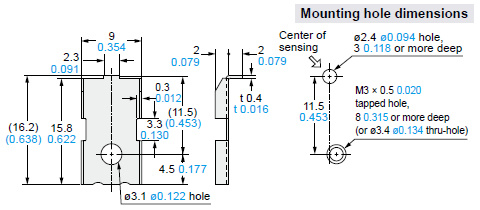
Dimensions
- Unit: mm in
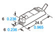
GX-F6□
Sensor
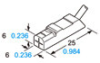
GX-H6□
Sensor
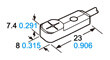
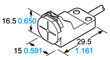
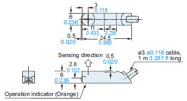
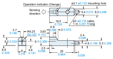
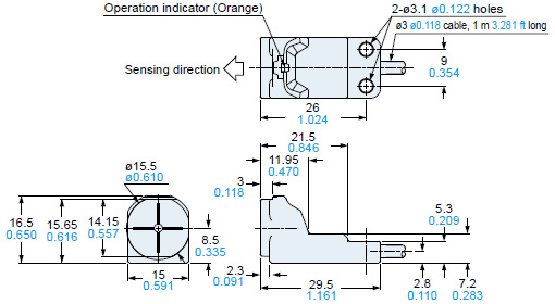
GX-F8□
Sensor
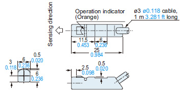
GX-H8□
Sensor
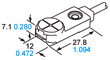
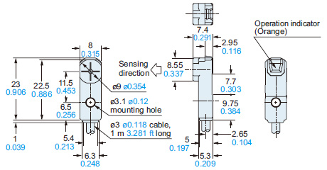
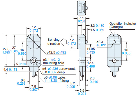
GX-F12□
Sensor
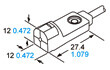
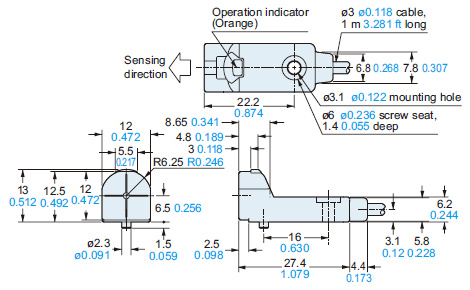
GX-H12□
Sensor
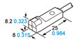
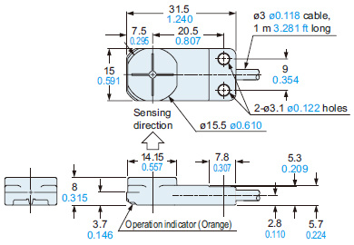
GX-F(L)15□
Sensor
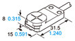
GX-H(L)15□
Sensor
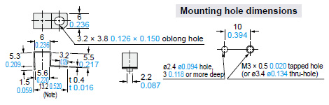
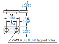
MS-GX6-1
Sensor mounting bracket (Optional)
Material: Stainless steel (SUS304)
MS-GL6-1
Sensor mounting bracket (Optional)
Material: Stainless steel (SUS301)
Note: 20 mm 0.787 in with the sensor fitted.
MS-GL6-2
Sensor mounting bracket (Optional)
Material: Stainless steel (SUS301)
Note: 13.4 mm 0.528 in with the sensor fitted.
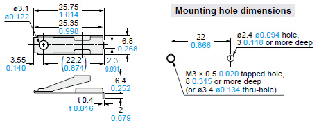
MS-GXL8-4
Sensor mounting bracket for GX-8 type (Optional)
Material:Stainless steel (SUS304)
1 pc. each of M3 (length 12 mm 0.472 in) truss head screw, nut, spring washer and plain washer are attached.
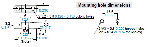
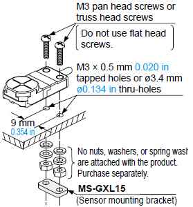
MS-GXL15
Sensor mounting bracket (Optional)
Material: Cold rolled carbon steel (SPCC)
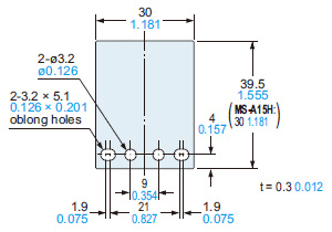
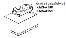
MS-A15F
MS-A15H
Aluminum sheet (Optional)
I/O Circuit and Wiring diagrams
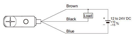
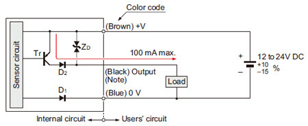
NPN output type
I /O circuit diagram
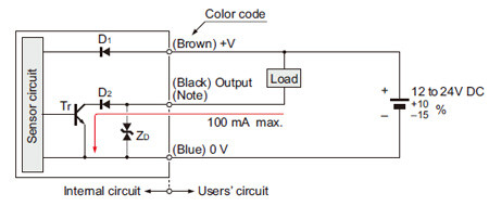
Symbols・・・
D1: Reverse supply polarity protection diode
D2: Reverse output polarity protection diode
ZD: Surge absorption zener diode
Tr : NPN output transistor
Note: The output does not incorporate a short-circuit protection circuit. Do not connect it directly to a power supply or a capacitive load.
Wiring diagram
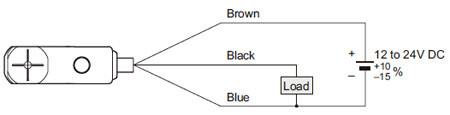
PNP output type
I/O circuit diagram
Symbols・・・
D1: Reverse supply polarity protection diode
D2: Reverse output polarity protection diode
ZD: Surge absorption zener diode
Tr : PNP output transistor
Note: The output does not incorporate a short-circuit protection circuit. Do not connect it directly to a power supply or a capacitive load.
Wiring diagram
Sensing characteristics
*TYPICAL
GX-6 type
Sensing field
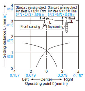
Correlation between sensing object size and sensing range
As the sensing object size becomes smaller than the standard size (iron sheet 12 × 12 × t 1 mm 0.472 × 0.472 × t 0.039 in), the sensing range shortens as shown in the left figure.
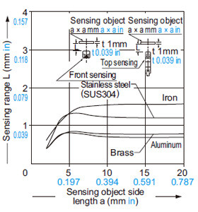
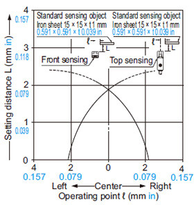
GX-8 type
Sensing field
Correlation between sensing object size and sensing range
As the sensing object size becomes smaller than the standard size (iron sheet 15 × 15 × t 1 mm 0.591 × 0.591 × t 0.039 in), the sensing range shortens as shown in the left figure.
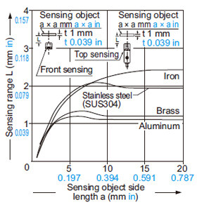
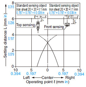
GX-12 type
Sensing field
Correlation between sensing object size and sensing range

As the sensing object size becomes smaller than the standard size (iron sheet 20 × 20 × t 1 mm 0.787 × 0.787 × t 0.039 in), the sensing range shortens as shown in the left figure.
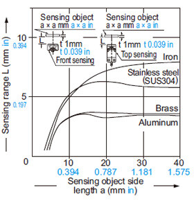
GX-15 type
Sensing field
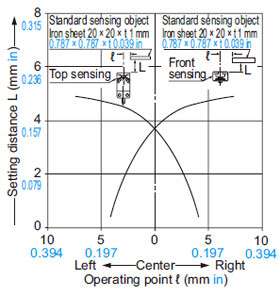
Correlation between sensing object size and sensing range

As the sensing object size becomes smaller than the standard size (iron sheet 20 × 20 × t 1 mm 0.787 × 0.787 × t 0.039 in), the sensing range shortens as shown in the left figure.
GX-15 (Long sensing range) type
Sensing field

Correlation between sensing object size and sensing range
As the sensing object size becomes smaller than the standard size (iron sheet 30 × 30 × t 1 mm 1.181 × 1.181 × t 0.039 in), the sensing range shortens as shown in the left figure.
Mounting
GX-6 type
- Use the optional sensor mounting bracket when installing.
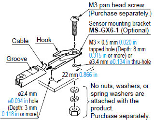
<When using MS-GX6-1 (Optional / recommended)>
- To mount the sensor with a nut, the mounting hole diameter should be ø3.4 mm ø0.134 in.
[1] Insert the sensor into the bracket as shown on the right.
[2] Push the sensor until the bracket hook is lodged in the groove on the upper portion of the sensor.
[3] Fix the bracket in place with M3 pan head screw.
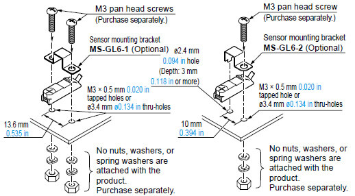
<When using MS-GL6-1(Optional) /MS-GL6-2 (Optional)>
- To mount the sensor with a nut, the mounting hole diameter should be ø3.4 mm ø0.134 in.
GX-8 type
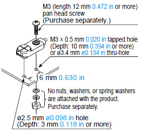
<When using MS-GXL8-4 (Optional)>
- Make sure to use a M3 (length: 12 mm 0.472 in or more) truss head screw (accessory for MS-GXL8-4).
The tightening torque should be 0.7 N·m or less. - To mount the sensor with a nut, the mounting hole diameter should be ø3.4 mm ø0.134 in.
- Do not use a flat head screw or a pan head screw.
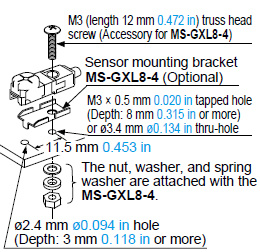
Note:Do not use a spring washer between the mounting screw and product.
GX-12 type
- The tightening torque should be 0.7 N·m or less.
- To mount the sensor with a nut, the mounting hole diameter should be ø3.4 mm ø0.134 in. Further, the hole in which the boss is inserted should be ø2.5 mm ø0.098 in and 3 mm 0.118 in, or more, deep.
Note:Do not use a spring washer between the mounting screw and product.
GX-15 type
- The tightening torque should be 1 N·m or less.
- To mount the sensor with a nut, the mounting hole diameter should be ø3.4 mm ø0.134 in.
- To mount the long sensing range GX-FL15□ or GX-HL15□ on a iron or stainless steel, the enclosed aluminum sheet MS-A15F(optional), MS-A15H (optional), or any other aluminum sheet having a minimum size of 30 × 39.5 × t0.3 mm 1.181 × 1.555 × 0.012 in (GX-FL15□), 30 × 30 × t0.3 mm 1.181 × 1.181 × 0.012 in (GX-HL15□), should be inserted between the sensor and the magnetic body.
However, it is not necessary to use the aluminum sheet when mounting on an insulator.
Note:Do not use a spring washer between the mounting screw and product.
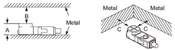
Influence of surrounding metal
- When there is a metal near the sensor, keep the minimum separation distance specified below.
Front sensing type
| GX-F6 type | GX-F8 type | GX-F12 type | GX-F15 type | GX-FL15 type | |
|---|---|---|---|---|---|
| A | 6 mm 0.236 in (Note 1) | 7.4 mm 0.291 in | 7.1 mm 0.280 in | 8 mm 0.315 in | 8 mm 0.315 in (Note 2) |
| B | 8 mm 0.315 in | 8 mm 0.315 in | 20 mm 0.787 in | 20 mm 0.787 in | 30 mm 1.181 in |
| C | 3 mm 0.118 in | 3 mm 0.118 in | 7 mm 0.276 in | 7 mm 0.276 in | 10 mm 0.394 in |
Notes:
1) When using MS-GX6-1 (recommended mounting bracket, optional), the distance “A” including the thickness of mounting bracket will be 6.4 mm 0.252 in.
2) The GXL-FL15 type should be mounted on an insulator. To mount it on an iron or stainless steel, use the enclosed aluminum sheet MS-A15F (optional).
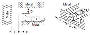
Top sensing type
| GX-H6 type | GX-H8 type | GX-H12 type | GX-H15 type | GX-HL15 type | |
|---|---|---|---|---|---|
| D | 3 mm 0.118 in | 4 mm 0.157 in | 7 mm 0.276 in | 6 mm 0.236 in | 12 mm 0.472 in |
| E | 10 mm 0.394 in | 10 mm 0.394 in | 20 mm 0.787 in | 20 mm 0.787 in | 30 mm 1.181 in |
| F | 2 mm 0.079 in | 3 mm 0.118 in | 3 mm 0.118 in | 0 mm 0 in | 10 mm 0.394 in (Note) |
| G | 2 mm 0.079 in | 3 mm 0.118 in | 3 mm 0.118 in | 3 mm 0.118 in | 10 mm 0.394 in |
Note: When GX-HL15 type is mounted on an insulator or seated on the enclosed aluminum sheet MS-A15H (optional), the distance “F” can be zero.
Mutual interference prevention
- When two or more sensors are installed in parallel or face to face, keep the minimum separation distance specified below to avoid mutual interference.
| H | J | ||
|---|---|---|---|
| GX-F6 GX-H6 type | Between “I” type and non “I” type | 0 mm (Note 2) | 15 mm 0.591 in |
| Between two “I” types or two non “I” types | 13 mm 0.512 in | 25 mm 0.984 in | |
| GX-F8 GX-H8 type | Between “I” type and non “I” type | 0 mm (Note 2) | 15 mm 0.591 in |
| Between two “I” types or two non “I” types | 20 mm 0.787 in | 35 mm 1.378 in | |
| GX-F12 GX-H12 type | Between “I” type and non “I” type | 0 mm (Note 2) | 25 mm 0.984 in |
| Between two “I” types or two non “I” types | 25 mm 0.984 in | 50 mm 1.969 in | |
| GX-F15 GX-H15 type | Between “I” type and non “I” type | 0 mm (Note 2) | 25 mm 0.984 in |
| Between two “I” types or two non “I” types | 45 mm 1.772 in | 70 mm 2.756 in | |
| GX-FL15 GX-HL15 type | Between “I” type and non “I” type | 0 mm (Note 2) | 25 mm 0.984 in |
| Between two “I” types or two non “I” types | 110 mm 3.059 in | 170 mm 6.693 in | |
Front sensing
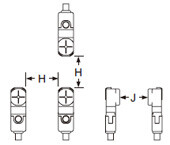
Top sensing
Notes:
1) “I” in the model No. specifies the different frequency type.
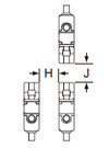
2) Close mounting is possible for up to two sensors.
When mounting three sensors or more at an equal spacing, align the model with “I” and the model without “I” alternately. The minimum value of dimension “H” should be as given below.
GX-F6 / H6 type: 3.5mm 0.138 in
GX-F8 / H8 type: 6mm 0.236 in
GX-F12 / H12 type: 6.5mm 0.256 in
GX-F15 / H15 type: 15mm 0.591 in
GX-FL15 / HL15 type: 47.5mm 1.870 in
Sensing range
- The sensing range is specified for the standard sensing object. With a non-ferrous metal, the sensing range is obtained by multiplying with the correction coefficient specified below. Further, the sensing range also changes if the sensing object is smaller than the standard sensing object or if the sensing object is plated.
Correction coefficient
| GX-F6 GX-H6 type | GX-F8 GX-H8 type | GX-F12 GX-H12 type | GX-F15 GX-H15 type | GX-FL15 type | GX-HL15 type | |
|---|---|---|---|---|---|---|
| Iron | 1 | 1 | 1 | 1 | 1 | 1 |
| Stainless steel (SUS304) | 0.76 approx. | 0.76 approx. | 0.79 approx. | 0.68 approx. | 0.70 approx. | 0.76 approx. |
| Brass | 0.50 approx. | 0.50 approx. | 0.56 approx. | 0.47 approx. | 0.45 approx. | 0.50 approx. |
| Aluminum | 0.48 approx. | 0.48 approx. | 0.53 approx. | 0.45 approx. | 0.43 approx. | 0.48 approx. |
Wiring
- The output does not incorporate a short-circuit protection circuit. Do not connect it directly to a power supply or a capacitive load.
Others
- This product has been developed / produced for industrial use only.
- This product is suitable for indoor use only.
- Do not use during the initial transient time (50 ms) after the power supply is switched on.