Basic Information
High-speed response and excellent workability

UL : Recognition
Features
Suitable for high-speed applications
It has a high performance of 3.3 kHz response frequency.
These sensors are ideal for sensing objects moving at high speeds.
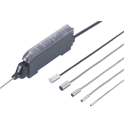
IP67G sensor head variations
The lineup includes 5 different models, from an ultracompact 2.8 mm 0.110 in diameter type to a spatterresistant type. Furthermore, all except for the GH-2SE are IP67G oil-resistant models so that they can be used with confidence even in adverse environments.

Excellent workability and ease of maintenance
It uses a quick-connection cable that is used in digital fiber sensors. It can be used in combination with fiber sensors and laser sensors, and can reduce the wiring of the power supply.
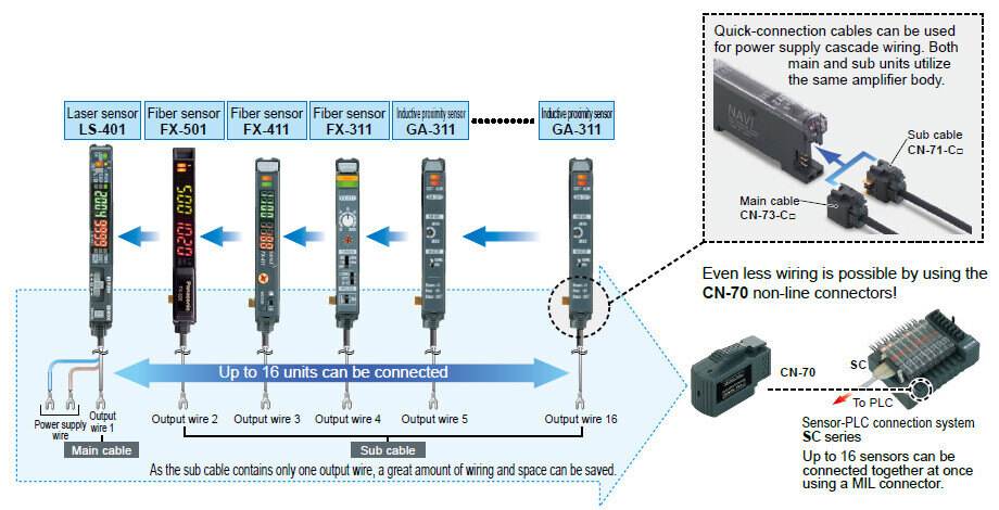
Labor-saving by one-touch connections
The connection between the sensor head and the amplifier is made using a quick-connection connector.
Past troublesome wiring connections using a screwdriver are no longer necessary.

Disconnection alarm indicator and operation indicator have been incorporated


Order guide
Sensor heads
| Type | Appearance (mm in) | Sensing range (Note) | Model No. | Hysteresis | ||
|---|---|---|---|---|---|---|
| Maximum operation distance | Stable sensing range | |||||
| Cylindrical type |
| 1.2mm 0.047 in | 0 to 0.6 mm 0 to 0.024 in | GH-2SE | 0.07 mm 0.0028 in or less | |
| 1.8mm 0.071 in | 0 to 0.8 mm 0 to 0.031 in | GH-3SE | 0.05 mm 0.0020 in or less | ||
| 2.4mm 0.094 in | 0 to 1.0 mm 0 to 0.039 in | GH-5SE | |||
| 4.0mm 0.157 in | 0 to 2.0 mm 0 to 0.079 in | GH-8SE | 0.04 mm 0.0016 in or less | ||
| Spatter resistant type | GH-F8SE | |||||
Note : The stable sensing range represents the sensing range for which the sensor can satisfy all the given specifications with the standard sensing object.
The maximum operation distance represents the maximum distance for which the sensor can detect the standard sensing object at +20 ℃ +68 ℉ constant ambient temperature.
Usage within the stable sensing range is recommended for accurate sensing applications.
Due to the characteristics of the potentiometer, it may be difficult to adjust the sensitivity at short distances.
Amplifier
Quick-connection cable is not supplied with the amplifier. Please order it separately.
| Type | Appearance | Model No. | Output |
|---|---|---|---|
| Connector type |
| GA-311 | NPN open-collector transistor |
Quick-connection cable
Quick-connection cable is not supplied with the amplifier. Please order it separately.
| Type | Model No. | Description | |
|---|---|---|---|
| Main cable (3-core) | CN-73-C1 | Length: 1 m 3.281 ft | 0.2 mm2 3-core cabtyre cable, with connector on one end Cable outer diameter: ø3.3 mm ø0.130 in |
| CN-73-C2 | Length: 2 m 6.562 ft | ||
| CN-73-C5 | Length: 5 m 16.404 ft | ||
| Sub cable (1-core) | CN-71-C1 | Length: 1 m 3.281 ft | 0.2 mm2 1-core cabtyre cable, with connector on one end Cable outer diameter: ø3.3 mm ø0.130 in |
| CN-71-C2 | Length: 2 m 6.562 ft | ||
| CN-71-C5 | Length: 5 m 16.404 ft | ||
(Note): The material of Quick-connection cable will be changed from production in March 2013, as soon as the previous ones are shipped out.
・Conductor cross-sectional area has been changed from 0.15mm2 to 0.2mm2.
・Sheath diameter has been changed from ø3.0mm to ø3.3mm.
Main cable
CN-73-C口

Sub cable
CN-71-C口

End plates
End plates are not supplied with the amplifier. Please order them separately when the amplifiers are mounted in cascade.
| Appearance | Model No. | Description |
|---|---|---|
| MS-DIN-E | When cascading multiple amplifiers, or when it moves depending on the way it is installed on a DIN rail, these end plates clamp amplifiers into place on both sides. Make sure to use end plates when cascading multiple amplifiers together. [ 2 pcs. per set ] |
Amplifier mounting bracket
MS-DIN-2

Sensor head mounting bracket
MS-SS口

Dimensions
Unit: mm in
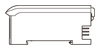
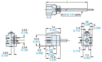
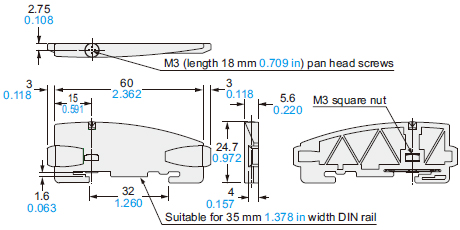
GA-311
Amplifier

Note:The front view shows the sensor head connector and quick-connection cable connector attached.The top view is without the sensor head connector, quick-connection cable and the cover.
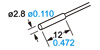
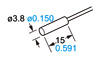
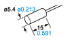
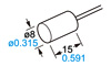
GH-2SE GH-3SE GH-5SE GH-8SE GH-F8SE
Sensor head

| Model No. | A | B | C |
|---|---|---|---|
| GH-2SE | ø2.8 ø0.110 | 12 0.472 | ø1.6 ø0.063 |
| GH-3SE | ø3.8 ø0.150 | 15 0.591 | ø2.5 ø0.098 |
| GH-5SE | ø5.4 ø0.213 | 15 0.591 | ø2.5 ø0.098 |
| GH-8SE | ø8.0 ø0.315 | 15 0.591 | ø2.5 ø0.098 |
| GH-F8SE | ø8.0 ø0.315 | 15 0.591 | ø2.65 ø0.104 |
CN-73-C1 CN-73-C2 CN-73-C5
Main cable (Optional)

• Length L
| Model No. | Length L |
|---|---|
| CN-73-C1 | 1,000 39.370 |
| CN-73-C2 | 2,000 78.740 |
| CN-73-C5 | 5,000 196.850 |
CN-71-C1 CN-71-C2 CN-71-C5
Sub cable (Optional)
• Length L
| Model No. | Length L |
|---|---|
| CN-71-C1 | 1,000 39.370 |
| CN-71-C2 | 2,000 78.740 |
| CN-71-C5 | 5,000 196.850 |
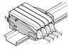
MS-DIN-2
Amplifier mounting bracket (Optional)
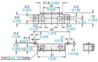
Material:Cold rolled carbon steel (SPCC) (Uni-chrome plated)
MS-DIN-E
End plate (Optional)
Material:Polycarbonate
MS-SS3 MS-SS5 MS-SS8
Sensor head mounting bracket (Optional)
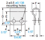
Material:Nylon 66
| Symbol | MS-SS3 | MS-SS5 | MS-SS8 |
|---|---|---|---|
| D | 16 0.630 | 18 0.709 | 20 0.787 |
| E | 9 0.354 | 10 0.394 | 11 0.433 |
| F | 6.3 0.248 | 8.3 0.327 | 10.3 0.406 |
| G | 4.9 0.193 | 6.1 0.240 | 6.5 0.256 |
| Applicable sensor head model No. | GH-3SE | GH-5SE | GH-8SE |
I/O Circuit and Wiring diagrams
I/O circuit diagram
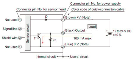
Note: The quick-connection sub cable does not have +V (brown) and 0 V (blue). The power is supplied from the connector of the main cable.
Symbols・・・
D : Reverse supply polarity protection diode
ZD: Surge absorption zener diode
Tr : NPN output transistor
Wiring diagram
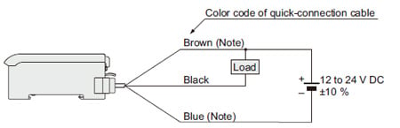
Note:The quick-connection sub cable does not have brown lead wire and blue lead wire.
Connector pin position


The graph on the left is plotted with the sensitivity adjusted so as to just detect a 5 × 5 × t 1 mm 0.197 × 0.197 × t 0.039 in iron sheet placed at a distance of 0.6 mm 0.024 in.

As the sensing object size becomes smaller than the standard size (iron sheet 5 × 5 × t 1 mm 0.197 × 0.197 × t 0.039 in), the sensing range shortens as shown in the left figure.
(The graph on the left is plotted with the sensitivity adjusted so as to just detect a 5 × 5 × t 1 mm 0.197 × 0.197 × t 0.039 in iron sheet placed at a distance of 0.6 mm 0.024 in.)

The graph on the left is plotted with the sensitivity adjusted so as to just detect a 5 × 5 × t 1 mm 0.197 × 0.197 × t 0.039 in iron sheet placed at a distance of 0.8 mm 0.031 in.

As the sensing object size becomes smaller than the standard size (iron sheet 5 × 5 × t 1 mm 0.197 × 0.197 × t 0.039 in), the sensing range shortens as shown in the left figure.
(The graph on the left is plotted with the sensitivity adjusted so as to just detect a 5 × 5 × t 1 mm 0.197 × 0.197 × t 0.039 in iron sheet placed at a distance of 0.8 mm 0.031 in.)

The graph on the left is plotted with the sensitivity adjusted so as to just detect a 5 × 5 × t 1 mm 0.197 × 0.197 × t 0.039 in iron sheet placed at a distance of 1.0 mm 0.039 in.

As the sensing object size becomes smaller than the standard size (iron sheet 5 × 5 × t 1 mm 0.197 × 0.197 × t 0.039 in), the sensing range shortens as shown in the left figure.
(The graph on the left is plotted with the sensitivity adjusted so as to just detect a 5 × 5 × t 1 mm 0.197 × 0.197 × t 0.039 in iron sheet placed at a distance of 1.0 mm 0.039 in.)

The graph on the left is plotted with the sensitivity adjusted so as to just detect a 10 × 10 × t 1 mm 0.394 × 0.394 × t 0.039 in iron sheet placed at a distance of 2.0 mm 0.079 in.

As the sensing object size becomes smaller than the standard size iron sheet 10 × 10 × t 1 mm 0.394 × 0.394 × t 0.039 in), the sensing range shortens as shown in the left figure.
(The graph on the left is plotted with the sensitivity adjusted so as to just detect a 10 × 10 × t 1 mm 0.394 × 0.394 × t 0.039 in iron sheet placed at a distance of 2.0 mm 0.079 in.)