Discontinued Products
Specifications
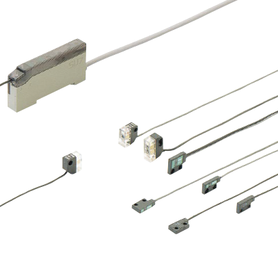
Sensor heads
Sensor heads (for general use)
| Type | Ultra-slim type | |||
|---|---|---|---|---|
| Thru-beam | Diffuse reflective | |||
| Front sensing | Side sensing | |||
| Model No. | SH-21 | SH-21E | SH-22 | |
| CE marking directive compliance | - | |||
| Applicable amplifiers | SU-7 series | |||
| Sensing range | 300 mm 11.811 in | 50 mm 1.969 in (Note 2) | ||
| Sensing object | Min. ø0.3 mm ø0.012 in opaque object (under the optimum condition) (Note 4) | Min. ø0.3 mm ø0.012 in copper wire (with 3 mm 0.118 in setting distance and at the max sensitivity) | ||
| Hysteresis | - | 15 % or less of operation distance (Note 2) | ||
| Repeatability (perpendicular to sensing axis) | 0.03 mm 0.001 in or less | 0.15 mm 0.006 in or less | ||
| Operation indicator | - | |||
| Pollution degree | - | |||
| Protection | IP62 (IEC) | |||
| Ambient temperature | -10 to +60 ℃ +14 to 140 ℉ (No dew condensation or icing allowed) Storage: -20 to +70 ℃ -4 to +158 ℉ | |||
| Ambient humidity | 35 to 85 % RH, Storage: 35 to 85 % RH | |||
| Ambient illuminance | Incandescent light: 3,500 lx or less at the light-receiving face | |||
| Vibration resistance | 10 to 55 Hz frequency, 1.5 mm 0.059 in double amplitude in X, Y and Z directions for two hours each | |||
| Shock resistance | 500 m/s2 acceleration (50 G approx.) in X, Y and Z directions three times each | |||
| Emitting element | Infrared LED (modulated) | |||
| Peak emission wavelength | 880 nm 0.035 mil | |||
| Material | Enclosure: Polycarbonate (glass fiber reinforced) | |||
| Cable | 0.089 mm2 (ultra-slim type: 0.057 mm2) single core (diffuse reflective type: two parallel single core wires) shielded cable, 3 m 9.843 ft long | |||
| Cable extension | Extension up to total 5 m 16.404 ft (ultra-small type: 10 m 32.808 ft) is possible with an equivalent cable (thru-beam type: both emitter and receiver). | |||
| Net weight | Emitter: 12 g approx. Receiver: 12 g approx. | 24 g approx. | ||
| Accessory | Sensor head mounting screw: 2 sets (SH-22: 1 set) | |||
| Type | Ultra-small type | |||
|---|---|---|---|---|
| Thru-beam | Diffuse reflective | |||
| Green LED | Red LED | |||
| Model No. | SH-31G | SH-33R | SH-32R | |
| CE marking directive compliance | EMC Directive, RoHS Directive | |||
| Applicable amplifiers | SU-7 series | |||
| Sensing range | 100 mm 3.937 in | 2 m 6.562 ft | 100 mm 3.937 in (Note 2) | |
| Sensing object | Min. ø1 mm ø0.039 in opaque object (with 100 mm 3.937 in setting distance and at the optimum sensitivity) (Note 5) | Min. ø1 mm ø0.039 in opaque object (with 2 m 6.562 ft setting distance and at the optimum sensitivity) (Note 5) | Opaque, translucent or transparent object (Note 3) | |
| Hysteresis | - | 15 % or less of operation distance (Note 2) | ||
| Repeatability (perpendicular to sensing axis) | 0.1 mm 0.004 in or less | 0.5 mm 0.020 in or less | ||
| Operation indicator | Red LED (lights up when the sensing output of the amplifier is ON, incorporated on the emitter of the thru-beam type sensor head) | |||
| Pollution degree | 3 (Industrial environment) | |||
| Protection | IP66 (IEC) | |||
| Ambient temperature | -25 to +60 ℃ -13 to +140 ℉ (No dew condensation or icing allowed) Storage: -30 to +70 ℃ -22 to +158 ℉ | |||
| Ambient humidity | 35 to 85 % RH, Storage: 35 to 85 % RH | |||
| Ambient illuminance | Incandescent light: 3,500 lx or less at the light-receiving face | |||
| Vibration resistance | 10 to 55 Hz frequency, 1.5 mm 0.059 in double amplitude in X, Y and Z directions for two hours each | |||
| Shock resistance | 500 m/s2 acceleration (50 G approx.) in X, Y and Z directions three times each | |||
| Emitting element | Green LED (modulated) | Red LED (modulated) | ||
| Peak emission wavelength | 570 nm 0.022 mil | 680 nm 0.027 mil | 700 nm 0.028 mil | |
| Material | Enclosure: ABS, Lens: Polycarbonate | |||
| Cable | 0.089 mm2 (ultra-slim type: 0.057 mm2) single core (diffuse reflective type: two parallel single core wires) shielded cable, 3 m 9.843 ft long | |||
| Cable extension | Extension up to total 5 m 16.404 ft (ultra-small type: 10 m 32.808 ft) is possible with an equivalent cable (thru-beam type: both emitter and receiver). | |||
| Net weight | Emitter: 10 g approx. Receiver: 10 g approx. | 20 g approx. | ||
| Accessory | - | |||
Note 1 :Where measurement conditions have not been specified precisely, the conditions used were an ambient temperature of +23 ℃ +73.4 ℉.
Note 2 :The sensing range and the hysteresis of the diffuse reflective type sensor are specified for white non-glossy paper (50 x 50 mm 1.969 x 1.969 in) as the object.
Note 3 :Make sure to confirm detection with an actual sensor before use.
Note 4 :The optimum condition is the condition when the sensitivity is adjusted so that the operation indicator just lights up at the given distance in the light received condition.
Note 5 :The optimum sensitivity stands for the sensitivity level when the operation indicator just lights up in the light received condition.
Sensor heads (for special use)
| Type | Mark sensor | |||
|---|---|---|---|---|
| Pinpoint | Line-focus | |||
| Red LED | Green LED | |||
| Model No. | SH-82R | SH-82G | SH-84R | |
| Applicable amplifiers | SU-7 series | |||
| Sensing range | 10 to 14 mm 0.394 to 0.551 in (Convergent point: 12 mm 0.472 in) (Spot diameter: ø0.7 mm ø0.028 in) (Note 2) | 10 to 14 mm 0.394 to 0.551 in (Convergent point: 12 mm 0.472 in) (Spot diameter: ø1 mm ø0.039 in) (Note 2) | 17 to 23 mm 0.669 to 0.906 in (Convergent point: 20 mm 0.787 in) (Spot size: 1 x 4 mm 0.039 x 0.157 in) (Note 2) | |
| Sensing object | Min. 0.07 mm 0.003 in width black line on white paper (with 12 mm 0.472 in setting distance and at the optimum sensitivity) (Note 4) | Min. 0.2 mm 0.008 in width black line on white paper (with 12 mm 0.472 in setting distance and at the optimum sensitivity) (Note 4) | Min. 0.07 mm 0.003 in width black line on white paper (Note 5) (with 20 mm 0.787 in setting distance and at the optimum sensitivity) (Note 4) | |
| Hysteresis | 10 % or less of operation distance (Note 2) | |||
| Repeatability (perpendicular to sensing axis) | 0.02 mm 0.0008 in or less | 0.03 mm 0.001 in or less | 0.03 mm 0.001 in or less (Note 6) | |
| Operation indicator | Red LED (lights up when the sensing output of the amplifier is ON) | |||
| Protection | - | |||
| Ambient temperature | -10 to +55 ℃ +14 to +131 ℉ (No dew condensation or icing allowed), Storage: -20 to +70 ℃ -4 to +158 ℉ | |||
| Ambient humidity | 35 to 85 % RH, Storage: 35 to 85 % RH | |||
| Ambient illuminance | Incandescent light: 3,500 lx or less (SH-61R: 2,000 lx or less) at the light-receiving face | |||
| Vibration resistance | 10 to 500 Hz frequency, 3 mm 0.118 in double amplitude (SH-72: 10 to 55 Hz frequency, 1.5 mm 0.059 in amplitude) in X, Y and Z directions for two hours each | |||
| Shock resistance | 500 m/s2 acceleration (50 G approx.) in X, Y and Z directions three times each | |||
| Emitting element | Red LED (modulated) | Green LED (modulated) | Red LED (modulated) | |
| Peak emission wavelength | 680 nm 0.027 mil | 570 nm 0.022 mil | 680 nm 0.027 mil | |
| Material | Enclosure: Polycarbonate, Lens: Acrylic | |||
| Cable | 0.089 mm2 single core, two parallel (SH-61R: 0.089 mm2 single core) shielded cables, 2 m 6.562 ft long (SH-72: 3 m 9.843 ft long) | |||
| Cable extension | Extension up to total 5 m 16.404 ft is possible with an equivalent cable (SH-61R: both emitter and receiver). | |||
| Net weight | 20 g approx. | |||
| Accessory | - | |||
| Type | Glass substrate detection sensor | |
|---|---|---|
| Model No. | SH-72 | |
| Applicable amplifiers | SU-7 series | |
| Sensing range | 0.5 to 7.5 mm 0.020 to 0.295 in (with transparent glass plate) | |
| Sensing object | □24 mm □0.945 in or more transparent glass, aluminum-evaporated mirror, etc. (Note 3) | |
| Hysteresis | 5 % or less of operation distance | |
| Repeatability (perpendicular to sensing axis) | 0.03 mm 0.001 in or less (along sensing axis) | |
| Operation indicator | - | |
| Protection | - | |
| Ambient temperature | -10 to +60 ℃ +14 to +140 ℉ (No dew condensation or icing allowed) Storage: -10 to +60 ℃ +14 to +140 ℉ | |
| Ambient humidity | 35 to 85 % RH, Storage: 35 to 85 % RH | |
| Ambient illuminance | Incandescent light: 3,500 lx or less (SH-61R: 2,000 lx or less) at the light-receiving face | |
| Vibration resistance | 10 to 500 Hz frequency, 3 mm 0.118 in double amplitude (SH-72: 10 to 55 Hz frequency, 1.5 mm 0.059 in amplitude) in X, Y and Z directions for two hours each | |
| Shock resistance | 500 m/s2 acceleration (50 G approx.) in X, Y and Z directions three times each | |
| Emitting element | Infrared LED (modulated) | |
| Peak emission wavelength | 880 nm 0.035 mil | |
| Material | Enclosure: Polycarbonate | |
| Cable | 0.089 mm2 single core, two parallel (SH-61R: 0.089 mm2 single core) shielded cables, 2 m 6.562 ft long (SH-72: 3 m 9.843 ft long) | |
| Cable extension | Extension up to total 5 m 16.404 ft is possible with an equivalent cable (SH-61R: both emitter and receiver). | |
| Net weight | 25 g approx. | |
| Accessory | - | |
Note 1 :Where measurement conditions have not been specified precisely, the conditions used were an ambient temperature of +23 ℃ +73.4 ℉.
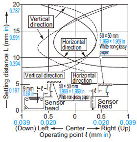
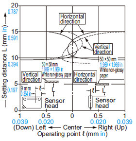
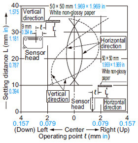
Note 2 :The sensing range and the hysteresis of the mark sensor are specified for white non-glossy paper (50 x 50 mm 1.969 x 1.969 in separatedin) as the object.
Note 3 :Make sure to confirm detection with an actual sensor before use.
Note 4 :The optimum sensitivity stands for the sensitivity level when the operation indicator just lights up in the light received condition.
Note 5 :The minimum sensing object for SH-84R is specified for the case when the sensor detects a black line with respect to the spot as shown below.

Note 6 :The repeatability for SH-84R is specified for the case when the sensing object approaches the spot sideways as shown below (0.12 mm 0.005 in if it approaches from above or below).

Sensor heads (for general use)
| Type | Ultra-small type | |
|---|---|---|
| Thru-beam | ||
| Red LED | ||
| Model No. | SH-31R | |
| CE marking directive compliance | EMC Directive, RoHS Directive | |
| Applicable amplifiers | SU-7 series | |
| Sensing range | 1 m 3.281 ft | |
| Sensing object | Min. ø1 mm ø0.039 in opaque object (with 1 m 3.281 ft setting distance and at the optimum sensitivity) (Note 5) | |
| Hysteresis | - | |
| Repeatability (perpendicular to sensing axis) | 0.1 mm 0.004 in or less | |
| Operation indicator | Red LED (lights up when the sensing output of the amplifier is ON, incorporated on the emitter of the thru-beam type sensor head) | |
| Pollution degree | 3 (Industrial environment) | |
| Protection | IP66 (IEC) | |
| Ambient temperature | -25 to +60 ℃ -13 to +140 ℉ (No dew condensation or icing allowed) Storage: -30 to +70 ℃ -22 to +158 ℉ | |
| Ambient humidity | 35 to 85 % RH, Storage: 35 to 85 % RH | |
| Ambient illuminance | Incandescent light: 3,500 lx or less at the light-receiving face | |
| Vibration resistance | 10 to 55 Hz frequency, 1.5 mm 0.059 in double amplitude in X, Y and Z directions for two hours each | |
| Shock resistance | 500 m/s2 acceleration (50 G approx.) in X, Y and Z directions three times each | |
| Emitting element | Red LED (modulated) | |
| Peak emission wavelength | 700 nm 0.028 mil | |
| Material | Enclosure: ABS, Lens: Polycarbonate | |
| Cable | 0.089 mm2 (ultra-slim type: 0.057 mm2) single core (diffuse reflective type: two parallel single core wires) shielded cable, 3 m 9.843 ft long | |
| Cable extension | Extension up to total 5 m 16.404 ft (ultra-small type: 10 m 32.808 ft) is possible with an equivalent cable (thru-beam type: both emitter and receiver). | |
| Net weight | Emitter: 10 g approx. Receiver: 10 g approx. | |
| Accessory | - | |
Note 1 :Where measurement conditions have not been specified precisely, the conditions used were an ambient temperature of +23 ℃ +73.4 ℉.
Note 2 :The optimum sensitivity stands for the sensitivity level when the operation indicator just lights up in the light received condition.
Sensor heads (for special use)
| Type | Chemical resistant type | |
|---|---|---|
| Thru-beam | ||
| Model No. | SH-61R | |
| Applicable amplifiers | SU-7 series | |
| Sensing range | 2.5 m 8.202 ft [5 to 80 mm 0.197 to 3.150 in when mounted on optional mounting bracket (MS-SH6-2) and used as convergent reflective type (Conv. point: 25 mm 0.984 in) (Note 2)] | |
| Sensing object | Min. ø5 mm ø0.197 in opaque object [Min. ø1 mm ø0.039 in steel wire when mounted on optional mounting bracket (MS-SH6-2) and used as convergent reflective type (with 25 mm 0.984 in setting distance and at the max. sensitivity)] | |
| Hysteresis | - [15 % or less of operation distance when mounted on optional mounting bracket (MS-SH6-2) and used as convergent reflective type. (Note 2)] | |
| Repeatability (perpendicular to sensing axis) | 0.1 mm 0.004 in or less [0.1 mm 0.004 in or less of operation distance when mounted on optional mounting bracket (MS-SH6-2) and used as convergent reflective type. (with 25 mm 0.984 in setting distance and at the optimum sensitivity (Note 3))] | |
| Operation indicator | Orange LED [lights up when the sensing output of the amplifier is ON, incorporated on the emitter] | |
| Protection (Note 8) | IP67 (IEC) | |
| Ambient temperature | -10 to +55 ℃ +14 to +131 ℉ (No dew condensation or icing allowed), Storage: -20 to +70 ℃ -4 to +158 ℉ | |
| Ambient humidity | 35 to 85 % RH, Storage: 35 to 85 % RH | |
| Ambient illuminance | Incandescent light: 3,500 lx or less (SH-61R: 2,000 lx or less) at the light-receiving face | |
| Vibration resistance | 10 to 500 Hz frequency, 3 mm 0.118 in double amplitude (SH-72: 10 to 55 Hz frequency, 1.5 mm 0.059 in amplitude) in X, Y and Z directions for two hours each | |
| Shock resistance | 500 m/s2 acceleration (50 G approx.) in X, Y and Z directions three times each | |
| Emitting element | Red LED (modulated) | |
| Peak emission wavelength | 644 nm 0.025 mil | |
| Material | Enclosure: Fluorine resin Cable sheath: Fluorine resin | |
| Cable | 0.089 mm2 single core, two parallel (SH-61R: 0.089 mm2 single core) shielded cables, 2 m 6.562 ft long (SH-72: 3 m 9.843 ft long) | |
| Cable extension | Extension up to total 5 m 16.404 ft is possible with an equivalent cable (SH-61R: both emitter and receiver). | |
| Net weight | Emitter: 15 g approx. Receiver: 15 g approx. | |
| Accessory | MS-SH6-1 (Sensor head mounting bracket): 2 pcs. | |
Note 1 :Where measurement conditions have not been specified precisely, the conditions used were an ambient temperature of +23 ℃ +73.4 ℉.
Note 2 :The sensing range and the hysteresis for the chemical resistant type sensor used in the convergent reflective mode is specified for white non-glossy paper (150 x 150 mm 5.906 x 5.906 in) as the object.
Note 3 :The optimum sensitivity stands for the sensitivity level when the operation indicator just lights up in the light received condition.
Amplifiers
| Type | Standard type | External synchronization input type | Remote sensitivity setting type | Remote sensitivity selection type | |
|---|---|---|---|---|---|
| Model No. (Note 2) | NPN output | SU-7(J) | SU-75 | SU-77 | SU-79 |
| PNP output | SU-7P | - | - | - | |
| Applicable sensor heads | SH series | ||||
| Supply voltage | 12 to 24 V DC ± 10 % Ripple P-P 10 % or less | ||||
| Current consumption | 35 mA or less | ||||
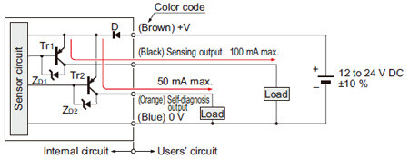
| Sensing output | <NPN output type> NPN open-collector transistor ・Maximum sink current: 100 mA ・Applied voltage: 30 V DC or less (between sensing output and 0 V) ・Residual voltage: 1.0 V or less (at 100 mA sink current) 0.4 V or less (at 16 mA sink current) <PNP output type> PNP open-collector transistor ・Maximum source current: 100 mA ・Applied voltage: 30 V DC or less (between sensing output and +V) ・Residual voltage: 2.0 V or less (at 100 mA source current) 1.0 V or less (at 16 mA source current) | ||||
| Utilization category | DC-12 or DC-13 | ||||
| Output operation | Selectable either Light-ON or Dark-ON with the ON and OFF buttons (Selectable with the external inputs for SU-77) | ||||
| Short-circuit protection | Incorporated | ||||
| Self-diagnosis output | <NPN output type> NPN open-collector transistor ・Maximum sink current: 50 mA ・Applied voltage: 30 V DC or less (between self-diagnosis output and 0 V) ・Residual voltage: 1.0 V or less (at 50 mA sink current) 0.4 V or less (at 16 mA sink current) <PNP output type> PNP open-collector transistor ・Maximum source current: 50 mA ・Applied voltage: 30 V DC or less (between self-diagnosis output and +V) ・Residual voltage: 2.0 V or less (at 50 mA source current) 1.0 V or less (at 16 mA source current) | ||||
| Output operation | ON under unstable sensing condition (restored automatically after 40 ms approx.), or if the sensing output is short-circuited (restored when short-circuit is rectified). (For the remote sensitivity adjustment type, it turns ON for 40 ms approx. Also after the remote sensitivity input is received.) | ||||
| Short-circuit protection | - | ||||
| Response time | 0.6 ms or less (0.8 ms or less when the interference prevention function is used) | ||||
| Operation indicator | Red LED (lights up when the sensing output is ON) | ||||
| Stability indicator | Green LED ("RUN" mode: Lights up under stable light received condition or stable dark condition "SET" mode: At the time of sensitivity setting, blinks twice when the difference between ON and OFF levels is greater than the hysteresis, but blinks 15 times when it is equal to or less than the hysteresis. Also blinks twice after the interference prevention is set "SET" mode → When "SIF" or "RUN" mode is selected: Blinks from 0 to 5 times according to the sensitivity margin) | ||||
| Test input (emission halt) function | - | Incorporated | - | - | |
| External synchronization function | - | Incorporated (Either gate or edge trigger is selectable) | - | - | |
| Remote sensitivity setting function | - | - | Incorporated | - | |
| Remote sensitivity selection function | - | - | - | Incorporated (Stores four sensitivities) | |
| Sensitivity shift & limit sensitivity setting functions | Shifts the set sensitivity level | ||||
| Interference prevention function | Incorporated | ||||
| Timer function | ON-delay / OFF-delay timer (variable 0 to 5 sec.) | - | ON-delay / OFF-delay timer (variable 0 to 5 sec.) | ||
| Pollution degree | 3 (Industrial environment) | ||||
| Ambient temperature | -10 to +55 ℃ +14 to +131 ℉ (No dew condensation or icing allowed), Storage: -20 to +70 ℃ -4 to +158 ℉ | ||||
| Ambient humidity | 35 to 85 % RH, Storage: 35 to 85 % RH | ||||
| Voltage withstandability | 1,000 V AC for one min. between all supply terminals connected together and enclosure | ||||
| Insulation resistance | 20 MΩ, or more, with 250 V DC megger between all supply terminals connected together and enclosure | ||||
| Vibration resistance | 10 to 150 Hz frequency, 0.75 mm 0.030 in double amplitude in X, Y and Z directions for two hours each | ||||
| Shock resistance | 100 m/s2 acceleration (10 G approx.) in X, Y and Z directions five times each | ||||
| Material | Enclosure: Heat-resistant ABS, Case cover: Polycarbonate, Cable lock lever: PPS | ||||
| Cable | 0.15 mm2 6-core (SU-7 and SU-7P: 0.2 mm2 4-core) cabtyre cable, 2 m 6.562 ft long | ||||
| Cable extension | Extension up to total 100 m 328.084 ft is possible with 0.3 mm2, or more, cable. | ||||
| Weight | Net weight: 65 g approx. | ||||
| Accessories | MS-DIN-2 (Amplifier mounting bracket): 1 pc., SU-CT1 (Stripper): 1 pc. | ||||
Note 1 :Where measurement conditions have not been specified precisely, the conditions used were an ambient temperature of +23 ℃ +73.4 ℉.
Note 2 :SU-7J is plug-in connector type.
Dimensions
- Unit: mm in
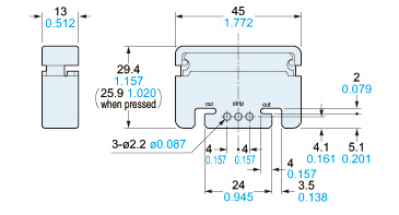
SU-7□(Discontinued products)
Amplifier
Assembly dimensions with attached amplifier mounting bracket
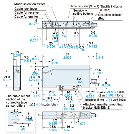
Notes:1) It is the external synchronization selection switch on SU-75.2) The top view is shown without the cover or the sensor head cable.
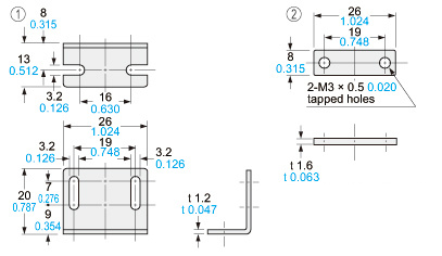
MS-DIN-2
Amplifier mounting bracket (Accessory for amplifier)
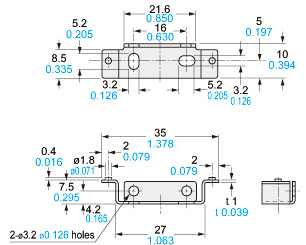
Material:Cold rolled carbon steel (SPCC) (Uni-chrome plated)
SH-21
Sensor head
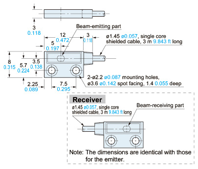
SH-21E
Sensor head
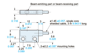
Note:The above dimensions are identical for the emitter and the receiver.
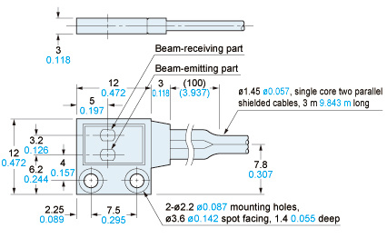
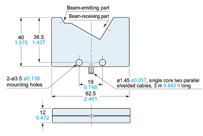
SH-22
Sensor head
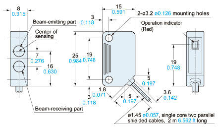
SH-31R(Discontinued products)
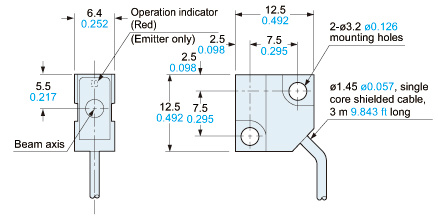
SH-31G
SH-33R
Sensor head
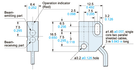
SH-32R(Discontinued products)
Sensor head
SU-CT1
Stripper (Accessory for amplifier)
Material:POM
MS-DS-1
Sensor head mounting bracket (Optional)
Material:Cold rolled carbon steel (SPCC) (Uni-chrome plated)Two M3 (length 14 mm0.551 in) screws with washers are attached.
MS-SS3-1
Sensor head mounting bracket (Optional)
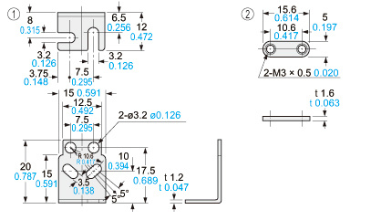
Material:Cold rolled carbon steel (SPCC) (Uni-chrome plated)Two M3 (length 12 mm0.472 in) screws with washers are attached.
Discontinued products
SH-82R
SH-82G
SH-84R
Sensor head
SH-72
Sensor head
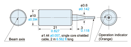
SH-61R
Sensor head
MS-SH6-1
Sensor head mounting bracket (Accessory for SH-61R)
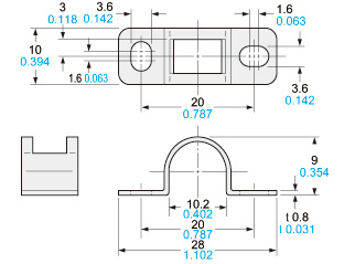
Material:Stainless steel(SUS304)
MS-SH6-2
Sensor head mounting bracket (Optional)
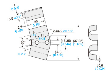
Material:Stainless steel(SUS304)
I/O Circuit and Wiring diagrams
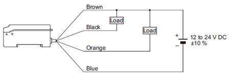
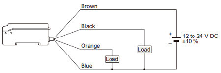
Standard type • NPN output
SU-7 SU-7J
I/O circuit diagram
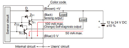
Symbols・・・
D : Reverse supply polarity protection diode
ZD1,ZD2: Surge absorption zener diode
Tr1,Tr2: NPN output transistor
Wiring diagram
External synchronization input type
SU-75
I/O circuit diagram
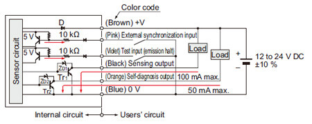
Symbols・・・
D : Reverse supply polarity protection diode
ZD1,ZD2: Surge absorption zener diode
Tr1,Tr2: NPN output transistor
Wiring diagram
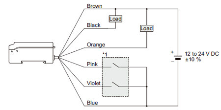
*1

Remote sensitivity setting type
SU-77
I/O circuit diagram
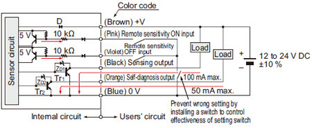
Symbols・・・
D : Reverse supply polarity protection diode
ZD1,ZD2: Surge absorption zener diode
Tr1,Tr2: NPN output transistor
Wiring diagram
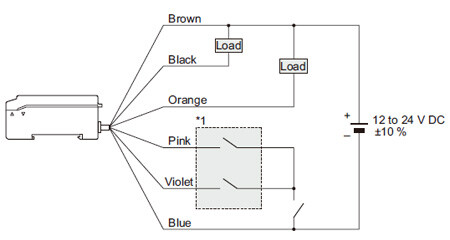
*1

Remote sensitivity selection type
SU-79
I/O circuit diagram
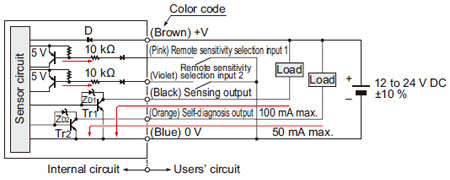
Symbols・・・
D : Reverse supply polarity protection diode
ZD1,ZD2: Surge absorption zener diode
Tr1,Tr2: NPN output transistor
Wiring diagram
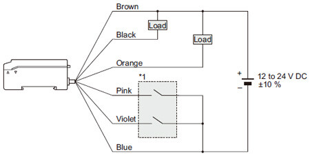
*1
Standard type • PNP output
SU-7P
I/O circuit diagram
Symbols・・・
D : Reverse supply polarity protection diode
ZD1,ZD2: Surge absorption zener diode
Tr1,Tr2: PNP output transistor
Wiring diagram
Sensing characteristics
*TYPICAL
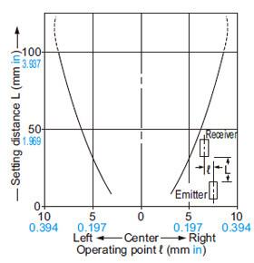
SH-21 SH-21E
Thru-beam type
Parallel deviation
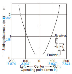
SH-31G
Thru-beam type
Parallel deviation
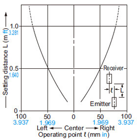
SH-33R
Thru-beam type
Parallel deviation
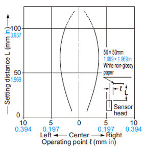
SH-22
Diffuse reflective type
Sensing field

Discontinued products
SH-31R
Thru-beam type
Parallel deviation
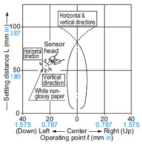
SH-32R
Diffuse reflective type
Sensing field
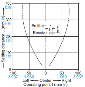
Correlation between sensing object size and sensing range
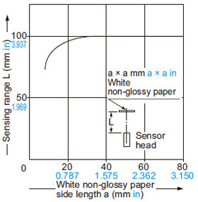
As the sensing object size becomes smaller than the standard size (white non-glossy paper 50 × 50 mm 1.969 × 1.969 in), the sensing range shortens, as shown in the left graph.
For plotting the left graph, the sensitivity has been set such that a 50 × 50 mm 1.969 × 1.969 in white non-glossy paper is just detectable at a distance of 100 mm 3.937 in.
SH-61R
Chemical resistant type
Parallel deviation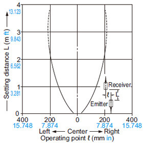
(MS-SH6-2)
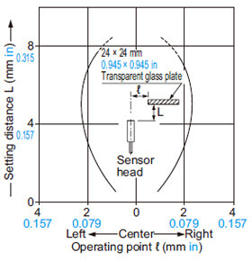
SH-72
Glass substrate detection sensor
Sensing field
SH-82R
Mark sensor
Sensing field
SH-82G
Mark sensor
Sensing field
SH-84R
Mark sensor
Sensing field
•Always use the sensor head and the exclusive amplifier together as a set.
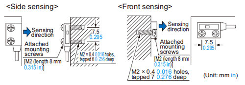
Mounting
- With tapped screws
・With attached screws and nuts
The tightening torque should be 0.14 N·m or less.
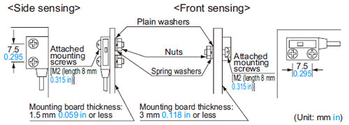
・The tightening torque should be 0.29 N·m or less when mounting the sensor head with the screws.
The tightening torque should be 0.14N·m or less.
For ultra-small type, mark sensor & glass substrate detection sensor

・Use M3 screws to mount the sensor head with the attached sensor head mounting bracket.
Chemical resistant type

・Use M4 screws to assemble the sensor head with the optional sensor head mounting bracket MS-SH6-2, in order to form the convergent sensing mode.

In case of chemical resistant type sensor head
Amplifier
- Do not use where it can be exposed to molten alkali metals (sodium, potassium, lithium, etc.), fluorine gas (F2), CIF3, OF2 (including gaseous state), etc.
- In case of cable extension, the extended portion should be placed in an area where it is not exposed to chemicals.
Wiring
- The self-diagnosis output does not incorporate a shortcircuit protection circuit. Do not connect it directly to a power supply or a capacitive load.
Sensitivity setting
・Normal sensitivity setting
| Standard setting |
|---|
| The sensor recognizes the ON (object present) and OFF (object absent) levels by your pressing of the buttons. The threshold level is automatically set at the middle between ON and OFF levels. |

・Maximum sensitivity setting
| Full power setting |
|---|
The maximum sensitivity is set. Take care that, in case of the diffuse reflective type, if a background object is present, the sensing output may turn ON even without the sensing object.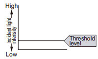 |
*How to set sensitivity with external inputs
| Remote sensitivity setting (SU-77 only) |
|---|
| Instead of pressing buttons, the sensitivity can be set with the remote sensitivity setting inputs. (There is no external sensitivity shift mode.) Setting procedure The procedure is the same as for setting with sensitivity buttons, except that instead of pressing the buttons, the remote sensitivity setting input wire is shortcircuited to 0 V. The mode selection switch is set to either the “SET” or “RUN” side. 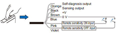 ・Time chart The self-diagnosis output stays ON for 40 ms approx. after ON input or OFF input is recognized by the sensor. (If the difference between the ON and OFF levels (the difference between incident light levels) is so small that stable detection is not possible, it does not turn ON.)  T1≥1,000ms、3,000ms>T2≥5ms、T3≈310ms、T4≈40ms、T5≥500ms Notes: 1)Signal condition ... Low: 0 to 1 V, High: 4.5 to 30 V, or open Input impedance: 10 kΩ 2):Do not move the object, etc., or change the incident light intensity during T3. |
・Sensitivity for detecting minute differences
| Limit sensitivity setting |
|---|
Setting for minute detection is possible just by pressing a button once without the object being present. For stable detection of an object without detecting the background
(Please note that the output operation cannot be reversed.)
|


・For applications in which beam intensity fluctuates
| Sensitivity shift |
|---|
If the incident light is stable in either the object present or object absent state, by shifting the threshold level towards this state, stable sensing is possible even if the incident light is unstable in the other state. The setting level is the same as for limit sensitivity setting. However, since the operating level is shifted after the normal sensitivity setting, output operation is selectable.
|

Remote sensitivity selection function (SU-79 only)
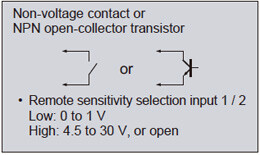
- SU-79 can store four channels of sensitivity levels, which can be selected as per your requirement. Designate the channel that is to store the sensitivity by making the remote sensitivity selection inputs 1 and 2 suitably High or Low.
Wiring
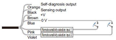
Signal condition Channel selection
Low: 0 to 1 V
High: 4.5 to 30 V, or open
Input impedance: 10 kΩ
| Input | Remote sensitivity selection input 1 | Remote sensitivity selection input 2 | |
|---|---|---|---|
| Channel | |||
| 1 | Low | Low | |
| 2 | Low | High | |
| 3 | High | Low | |
| 4 | High | High | |
External synchronization function (SU-75 only)
- The external synchronization function can be used to control the timing of sensing. Edge trigger or gate trigger are available.

T≥0.6ms(T≧0.8ms when the interference prevention function is used)
Note:The external synchronization selection switch must be turned fully clockwise or counterclockwise.
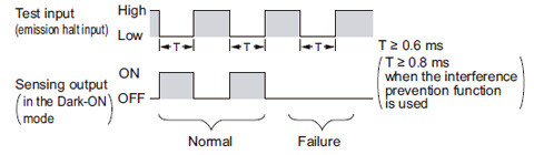
Test input (emission halt) function (SU-75 only)
- When the test input (emission halt input) (violet) is shortcircuited to 0 V (Low), the beam emission is halted. This function is useful for a start-up test since the sensing output can be made ON / OFF without the sensing object. Short-circuit to 0 V and open the input, repeatedly. If the sensing output follows this operation, the sensor is working well, else not.
Timer function (Excluding SU-75)
- Every SU-7 series amplifier (excluding SU-75) is incorporated with a variable ON / OFF delay timer for 0 to 5 sec.
ON-delay
As only longer signals are extracted, this function is useful for detecting if a line is clogged, or for sensing only objects taking a long time to travel.
OFF-delay
Since the output signal is extended for a fixed time interval, this function is useful if the output signal is so short that the connected device cannot respond.
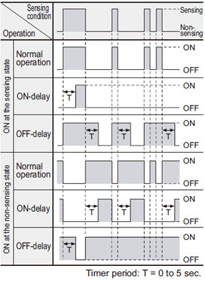
- Timer period setting
Adjust the time duration of ON or OFF delay by turning the timer adjuster.
Note:Adjust the timer under “SET” mode. Adjustment is not allowed in “SIF” or “RUN” mode.

Self-diagnosis function
- The sensor checks the incident light intensity, and if it is reduced due to dirt or dust, or beam misalignment, an output is generated.

[1]The self-diagnosis output transistor stays in the “OFF” state during stable sensing.
[2]When the sensing output changes, if the incident light intensity does not reach the stable light received level or the stable dark level, the self-diagnosis output becomes ON. It is automatically restored after 40 ms approx. Further, the self-diagnosis output changes state when the sensing output changes from Light to Dark state.
It is not affected by the output operation of the sensing output.
[3]In case of insufficient beam interruption, there will be a time lag before the self-diagnosis output turns ON.
Others
- Do not use during the initial transient time (0.5 sec.) after the power supply is switched on.
Use conditions to comply with CE Marking
(SH-3□ only)
Place ferrite core at the sensor cable.
- Following work must be done in cace of using this product as a CE marking (European standard EMC Directive) conforming product.


Place a ferrite core near the amplifier.
In that condition, the sensor head cable should be single-winding.
Prepare 1 pc. of the following recommended ferrite core (or an equivalent product.)
<Recommended product>
ESD-SR-110 [NEC TOKIN Corporation]