Discontinued Products
Dimensions
- Unit: mm in
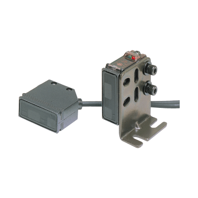
RX-LS200 RX-LS200-P
Sensor

PT-RX500 PT-RX1000
Protective tube (Optional)

MS-RX-1
Sensor mounting bracket (Accessory)
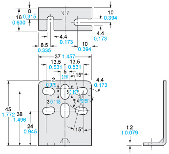
Material:Cold rolled carbon steel (SPCC)Two M4 (length 16 mm0.630 in) hexagon-socket-head bolts are attached.
Assembly dimensions

I/O Circuit and Wiring diagrams
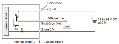
NPN output type
RX-LS200
I/O circuit diagram
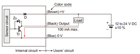
Symbols・・・D :Reverse supply polarity protection diodeZD:Surge absorption zener diodeTr:NPN output transistor
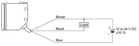
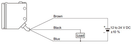
Wiring diagram
PNP output type
RX-LS200-P
I/O circuit diagram
Note:The output does not incorporate a short-circuit protection circuit.Do not connect it directly to a power supply or a capacitive load.
Symbols・・・
D :Reverse supply polarity protection diode
ZD:Surge absorption zener diode
Tr:PNP output transistor
Wiring diagram
Sensing characteristics
*TYPICAL
Sensing fields
・Setting distance: 200 mm
7.874 in (Horizontal)
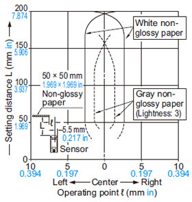
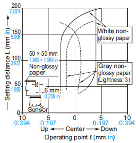
・Setting distance: 200 mm
7.874 in (Vertical)
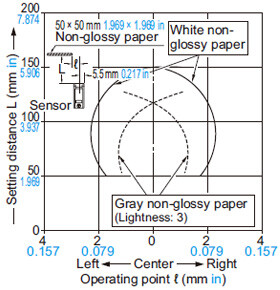
・Setting distance: 150 mm
5.906 in (Horizontal)
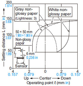
・Setting distance: 150 mm
5.906 in (Vertical)
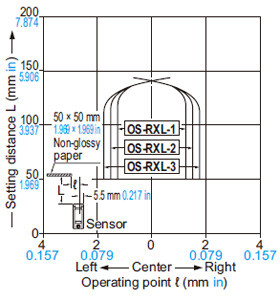
・Setting distance: 150 mm
5.906 in with slit mask (Horizontal)
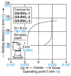
・Setting distance: 150 mm
5.906 in with slit mask (Vertical)
Correlation between sensing object size and sensing range
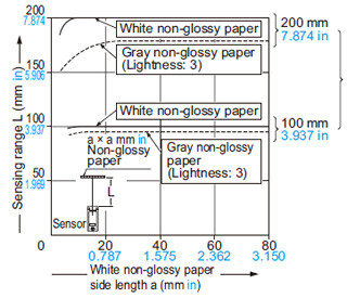
These curves show the characteristics with the maximum sensing range set to 100 mm 3.937 in, 200 mm 7.874 in, each, with white non-glossy paper (50 × 50 mm 1.969 × 1.969 in).
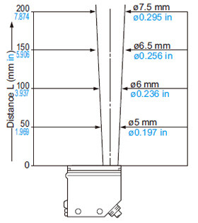
Emitted beam
Correlation between material (50 × 50 mm 1.969 × 1.969 in) and sensing range
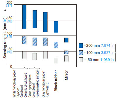
These bars indicate the sensing range with respective objects when the distance adjuster is set at the sensing range of 200 mm 7.874 in, 100 mm 3.937 in and 50 mm 1.969 in long, each, with white non-glossy paper.
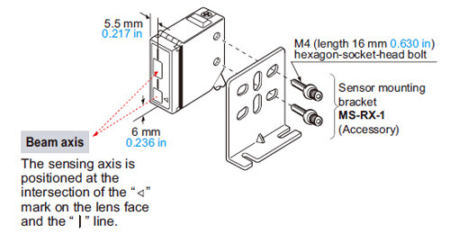
Mounting
- The tightening torque should be 1.17 N·m or less.
- Care must be taken regarding the sensor mounting direction with respect to the object’s direction of movement.
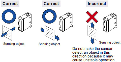
- When detecting a specular object (aluminum or copper foil) or an object having a glossy surface or coating, please take care that there are cases when the object may not be detected due to a small change in angle, wrinkles on the object surface, etc.
- When a specular body is present below the sensor, use the sensor by tilting it slightly upwards to avoid wrong operation.
- If a specular body is present in the background, wrong operation may be caused due to a small change in the angle of the background body. In that case, install the sensor at an inclination and confirm the operation with the actual sensing object.
- Do not install the sensor at a distance of less than 50 mm 1.969 in from the object because the sensing is unstable in this range.
Wiring
- The output of RX-LS200-P does not incorporate a shortcircuit protection circuit. Do not connect it directly to a power supply or a capacitive load.
Use conditions to comply with CE Marking
- Following work must be done in case of using this product as a CE marking (European standard EMC Directive) conforming product.
Ensure that the shield is connected to 0 V or the actual ground.
・In case of connecting a sensor to power supply 0 V by using a shield (piping, etc.)
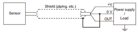
Note: The shield (piping, etc.) must be insulated.
・In case of grounding by using a shield (piping, etc.)

Others
- Do not use during the initial transient time (50 ms) after the power supply is switched on.
Distance adjustment
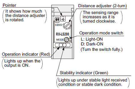
Adjusters
Adjusting procedure
<When a sensing object moves horizontally to the sensor>
| Step | Description | Distance adjuster |
|---|---|---|
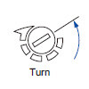
| [1] | Turn the distance adjuster fully counterclockwise to the minimum sensing range position (50 mm 1.969 in approx.). (Do not turn excessively.) |
|
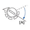
| [2] | Place an object at the required distance from the sensor, turn the distance adjuster gradually clockwise, and find out point " [A] " where the sensor changes to the light received condition. |
|
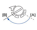
| [3] | Remove the object, turn the distance adjuster further clockwise, and find out point " [B] " where the sensor changes to the light received condition again with only the background. (When the sensor does not go to the light received condition even if the adjuster is fully turned clockwise, point " [B] " is this extreme point.) |
|
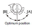
| [4] | The optimum position to stably detect objects is the center point between " [A] " and " [B] ". |
|
<When a sensing object is approaching / moving away from the sensor>
- Follow only steps [1] and [2] respectively. Since the sensing point may change depending on the sensing object, be sure to check the operation with the actual sensing object.