Basic Information
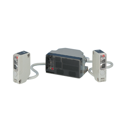
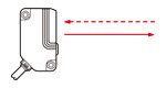
Compact size sensor realizes wide sensing area & long sensing range


CE : EMC Directive
UKCA : EMC Regulations
Features
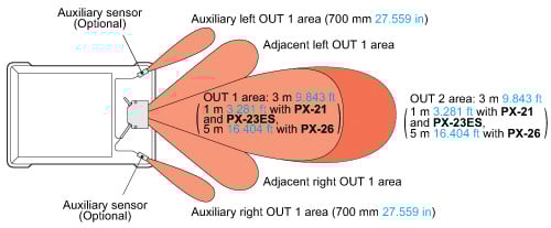
Ideal sensing area with very little dead zone
The advanced optical system of the PX-2 series reduces the dead zones in front of an automatic guided vehicle (AGV).
The dead zones at the sides are further minimized if auxiliary sensors which can be easily mounted with connectors are used.
(For PX-24, PX-24ES, PX-23ES and PX-26)
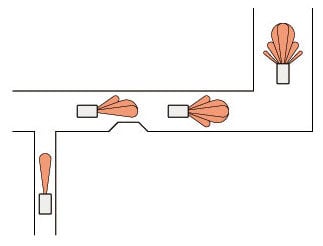
Sensing areas selectable as per route condition
Sensing areas can be selected with switches to suit the route conditions of an AGV.
Further, in case of PX-24ES and PX-23ES, the sensing areas can also be selected with external signals.
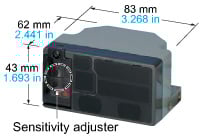
Compact size for space-saving
Its size is half of a conventional model, and the attached cable orientation is freely adjustable. Hence, it can also fit in a small AGV.
Moreover, sensitivity adjustment can be done on the front face.
Long sensing range 5 m 16.404 ft type
PX-26 has a long sensing range of 5 m 16.404 ft. Even on a high-speed AGV, it can detect an object quite early so that slowing down and stopping are smooth.
Sleep function
The sensor can be put into the sleep (stand-by) condition when it is not used and can be restored to operating condition by an external signal.
Consequently battery is conserved as the power consumption is reduced to 1/5.
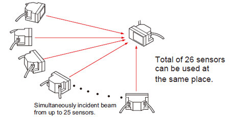
Automatic interference prevention function
One PX-2 sensor can simultaneously receive beams from 25 Nos. of other PX-2 sensors without resulting in any interference. Even if AGVs are facing each other, the PX-2 sensor on one AGV reliably detects the other AGVs.
Hence, it can be safely used even at a place where several AGVs are moving.
External sensitivity adjustment
The sensitivity of the sensor can be adjusted, within the range set by the manual adjuster, by an external input.
(For PX-24, PX-24ES, PX-23ES and PX-26)
Order guide
Main Sensors
| Type | Appearance | Sensing range | Model No. | ||
|---|---|---|---|---|---|
| Standard type |
| 3 m 9.843 ft | PX-22 | ||
| Short sensing range | 1 m 3.281 ft | PX-21 | |||
| Auxiliary sensor connectable type | 3 m 9.843 ft | PX-24 | |||
| With external control function | PX-24ES | ||||
| Short sensing range | 1 m 3.281 ft | PX-23ES | |||
| Long sensing range | 5 m 16.404 ft | PX-26 | |||

Auxiliary sensor
| Type | Appearance | Sensing range | Model No. |
|---|---|---|---|
| Auxiliary sensor |
| 700 mm 27.559 in | PX-SB1 |
Accessories
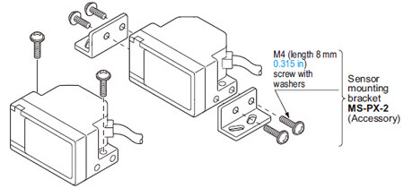
MS-PX-2 (Main sensor mounting bracket)
Two bracket set [Four M4 (length 8 mm0.315 in) screws with washers are attached.]
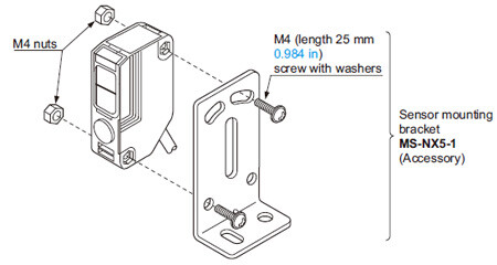
MS-NX5-1 (Auxiliary sensor mounting bracket)
Two M4 (length 25 mm0.984 in) screws with washers and two M4 nuts are attached.
Option
| Designation | Model No. | Description |
|---|---|---|
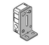
| Auxiliary sensor mounting bracket | MS-NX5-2 | Foot biangled mounting bracket (Sensor protection bracket) |
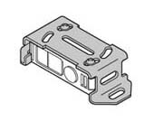
| MS-NX5-3 | Back angled mounting bracket |
Auxiliary sensor mounting bracket
MS-NX5-2
Two M4 (length 25 mm0.984 in) screws with washers and two M4 nuts are attached.
MS-NX5-3
Two M4 (length 25 mm0.984 in) screws with washers and two M4 nuts are attached.
Dimensions
- Unit: mm in
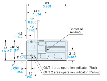
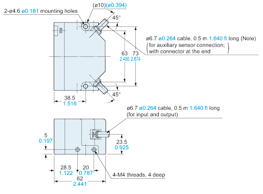
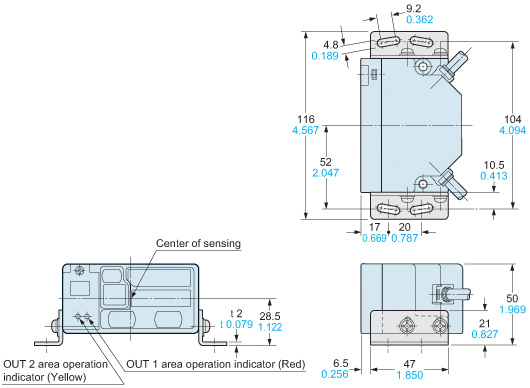
PX-2□
Main sensor
Note:PX-22 and PX-21 do not have this cable.
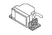
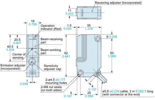
PX-SB1
Auxiliary sensor
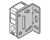
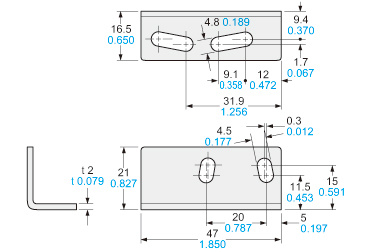
MS-PX-2
Main sensor mounting bracket (Accessory for PX-2□)
- Left side
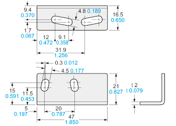
Material:Cold rolled carbon steel (SPCC) (Uni-chrome plated)Four M4 (length 8 mm0.315 in) screws with washers are attached.
- Right side
Assembly dimensions
Mounting drawing with PX-24
I/O Circuit and Wiring diagrams
PX-24ES PX-23ES
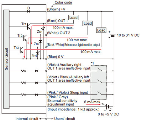
I/O circuit diagram
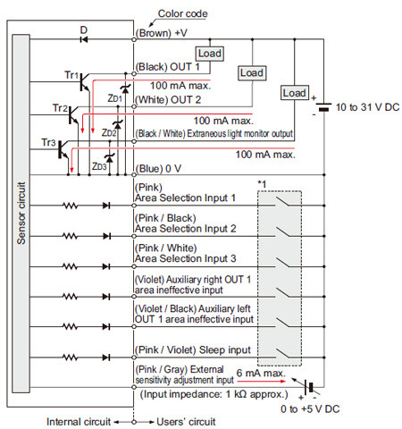
Symbols・・・
D : Reverse supply polarity protection diode
ZD1,ZD2,ZD3: Surge absorption zener diode
Tr1,Tr2,Tr3: NPN output transistor
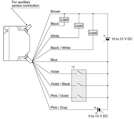
Wiring diagram
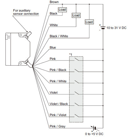
*1

(Note) :
Please refer to "Cautions for Use - Selection of sensing area".
PX-22 PX-21
I/O circuit diagram
Symbols・・・
D : Reverse supply polarity protection diode
ZD1,ZD2: Surge absorption zener diode
Tr1,Tr2: NPN output transistor
Wiring diagram
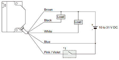
*1
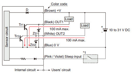
PX-24 PX-26
I/O circuit diagram
Symbols・・・
D : Reverse supply polarity protection diode
ZD1,ZD2,ZD3: Surge absorption zener diode
Tr1,Tr2,Tr3: NPN output transistor
Wiring diagram
*1

Sensing characteristics
How to read sensing characteristics
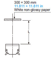
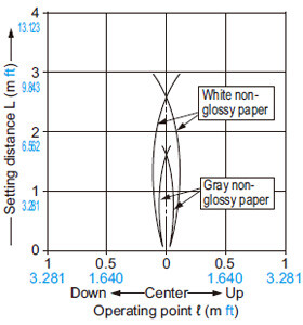
- Sensing field
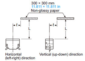
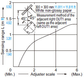
Note:The sensitivity has been adjusted so that the maximum sensing range for white non-glossy paper (300 × 300 mm11.811 × 11.811 in) is 3 m9.843 ft(1 m3.281 ftforPX-21andPX-23ES, 5 m16.404 ftforPX-26) with the L., C. and R. areas effective.
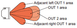
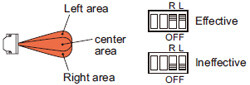
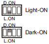
Sensing area
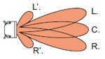
L. : Left area
C. : Center area
R. : Right area
L’. : Adjacent left OUT 1 area
R’. : Adjacent right OUT 1 area
Sensing object
| Type of non-glossy paper |
|---|
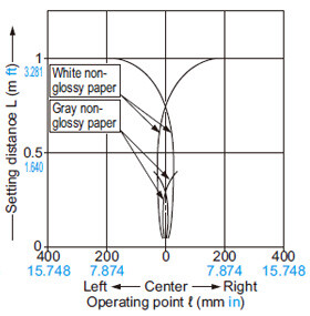
| White non-glossy paper (lightness: 9) |
| Gray non-glossy paper (lightness: 5) |
| Black non-glossy paper (lightness: 2) |
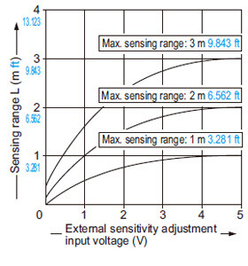
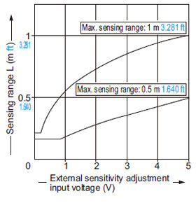
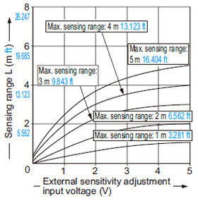
- Correlation between external sensitivity adjustment input voltage and sensing range
It shows the variation in the sensing range when the external input voltage is changed from 0 to +5 V with the sensitivity adjuster set at the maximum sensing range.
Please note that due to the adjuster’s characteristics it may be difficult to adjust the sensitivity at a close distance or near to rated sensing distances. (Refer to “Correlation between sensitivity adjustor and sensing range” below.)
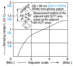
- Correlation between sensitivity adjuster and sensing range
All models
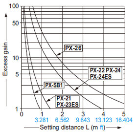
Correlation between setting distance and excess gain
PX-22 PX-24 PX-24ES
Sensing fields
• All areas effective (Horizontal)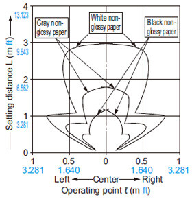
Correlation between external sensitivity adjustment input voltage and sensing range
(Excluding PX-22)
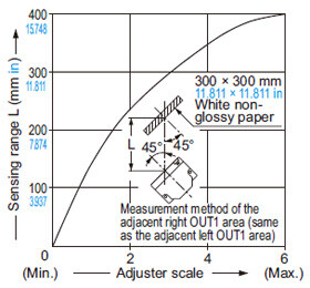
Correlation between sensitivity adjuster and sensing range
• OUT1(OUT2) area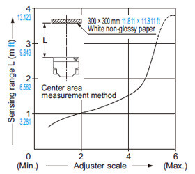
PX-21 PX-23ES
Sensing fields
• All areas effective (Horizontal)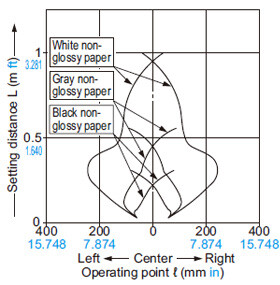
Correlation between external sensitivity adjustment input voltage and sensing range
(PX-23ES only)
Correlation between sensitivity adjuster and sensing range
• OUT1 (OUT2) area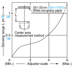
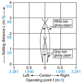
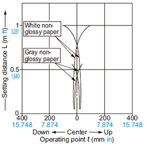
PX-26
Sensing fields
• Horizontal [All areas effective (Note)]![Horizontal [All areas effective]](https://ap.industry.panasonic.com/hubfs/pid-corp/products/fasys/sensor/photoelectric/px-2/characteristic/images/pic18.jpg)
Note: Area selection is not possible.
• Vertical [All areas effective (Note)]![Vertical [All areas effective (Note)]](https://ap.industry.panasonic.com/hubfs/pid-corp/products/fasys/sensor/photoelectric/px-2/characteristic/images/pic19.jpg)
Correlation between external sensitivity adjustment input voltage and sensing range
Correlation between sensitivity adjuster and sensing range
• OUT1 (OUT2) area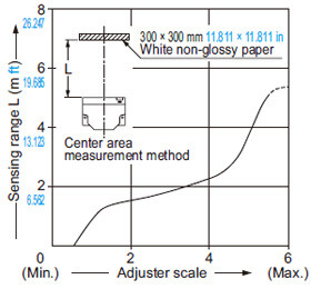
PX-SB1
Sensing field
• Horizontal and vertical directions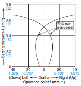
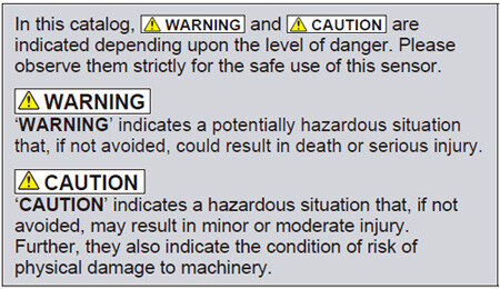
Hazard Indications
- Installation of a touch bumper
You are requested to always install a touch bumper when this product is used on an automatic guided vehicle (AGV).
- Use outside Japan
This sensor conforms to the EMC Directive (CE Marking) and EMC Regulations (UKCA Marking). However, it is not certified by a competent body in accordance with other country safety standards. Since each country has its regulations, please follow the local and national regulations of the country where this sensor is used.
- Fail-safe measures
This sensor is meant for proximity detection and does not possess control functions for safety maintenance. If fail-safe measures are required, consider their incorporation in the total system. Further, do not connect the sensor output directly to a stopping mechanism (brake).
- Periodical maintenance check
The person in charge must periodically confirm the performance of the product and maintain a record of such checks. In addition, whenever the operating environment of the product is changed due to system modification, etc., performance check must be done.
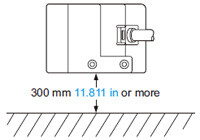
Mounting
・The tightening torque for the main sensor should be 1.2 N·m or less.
・The tightening torque for PX-SB1 (auxiliary sensor) should be 0.8 N·m or less.
・Mount the sensor, horizontally, at least 300 mm 11.811 in above the floor, to avoid reflection from the floor.
Automatic interference prevention function
・In case several sensors are used at the same place, take care that the number of sensors from which beams may be simultaneously incident is 25 sensors or less.
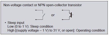
Sleep function
Notes: 1)Response time of the sleep input is 50ms.
2)Reactivation from the sleep state to the operation state takes 0.7 sec. approx. Operation during this transient state should be avoided.
3)When the sleep function is not used, keep the sleep input wire open or insulated and prevent contact with other wires.
- When the sleep input is made Low, the sensor goes into the sleep state and the operation can be stopped.
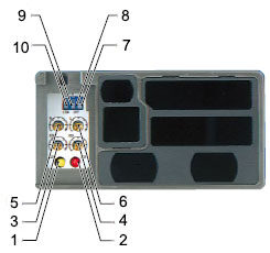
Part description
| Sign | Item | Description | |
|---|---|---|---|
| 1 | Operation indicator | OUT 2 area (Yellow LED) | Lights up when the beam is received in the OUT 2 area. |
| 2 | OUT 1 area (Red LED) | Lights up when the beam is received in the OUT 1 area. | |
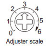
| 3 | Sensitivity adjuster | OUT 2 area | Sensing area sensitivity adjuster.
|
| 4 | OUT 1 area | ||
| 5 | Adjacent right OUT 1 area | ||
| 6 | Adjacent left OUT 1 area | ||
| 7 | Sensing area selection switch (Note 1) | Left area | Selection of main sensor sensing areas. (OUT 1,OUT 2 )
|
| 8 | Right area | ||
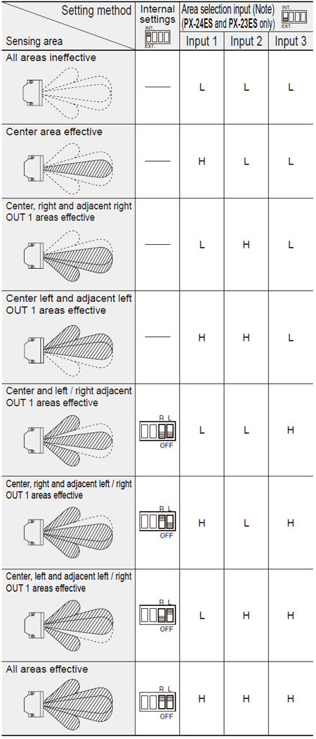
| 9 | Output operation mode selection switch |
| |
| 10 | External control function selection switch (Note 2) |
| |
Notes: 1)Not incorporated in PX-26.
2)Incorporated in PX-24ES and PX-23ES.
Others
- Do not use during the initial transient time (0.7 sec.) after the power supply is switched on.
- Take care that an initial rush current (1.5 A approx. at 10 V DC and 5 A approx. at 31 V DC) will flow when the power supply is switched on.
PX-22 PX-21 PX-24 PX-24ES PX-23ES
Selection of sensing area
L: Low (0 to 1V), H: High (4.5 to 31V, or open)
Note: Response time of area the selection input is 80 ms.
PX-24 PX-24ES PX-23ES PX-26
External sensitivity adjustment function
Notes: 1)The sensitivity of the auxiliary sensor is not changed.
2)Sensitivity adjustment beyond the range set by the manual sensitivity adjuster is not possible.
- The sensitivity can be adjusted, within the range set by the manual sensitivity adjuster, by an analog voltage (0 to +5 V) applied to the external sensitivity adjustment input. The sensitivity varies with the magnitude of the applied voltage.
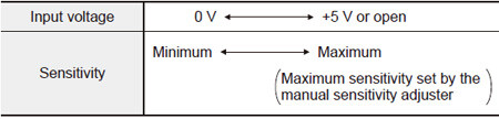
3)This wire should be insulated if it is not used.
Extraneous light monitor function
(Not incorporated in PX-22 and PX-21)
- If the sensor receives modulated light other than its own (including auxiliary sensor’s) light, the extraneous light monitor output turns ON. The operation of the extraneous light monitor output has absolutely no affect on sensing. It is useful for recognizing presence of other sensors near this sensor in case of intersecting AGV paths, etc.
Note:
The extraneous light monitor output is not incorporated with a short-circuit protection circuit. Do not connect it directly to a power supply or a capacitive load.
PX-SB1
• This sensor must always be used with the applicable main sensor. This sensor does not work as a standalone unit. (It cannot be used with PX-22 or PX-21.)
Selection of auxiliary area
- Aux area can be selected by aux area ineffective input of the main sensor.
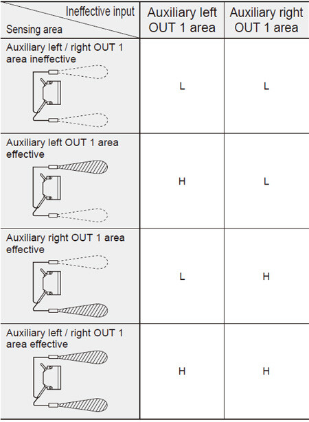
L: Low (0 to 1 V), H: High (4.5 to 31 V or open)
Note: Aux area disable input has nothing to do with the external control function selection switch of the main sensor.
Sensitivity setting
- Sensitivity adjustment of PX-SB1 is performed with the emitter volume. If sensitivity cannot be set to close range even after adjusting the emitter volume, then an aux sensor might be receiving the light from the main sensor. If that is the case, adjust sensitivity with the emitter volume and the receiver volume. For details, see the instruction manual that comes with the product.
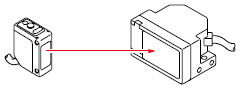
Connection with the main sensor

- Connect the main sensor connector attached cable to the aux sensor connector attached cable.
- The spiral lead wire side of the main sensor connector attached cable is the left aux sensor side.