Discontinued Products

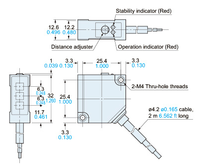
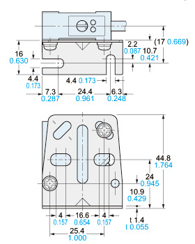
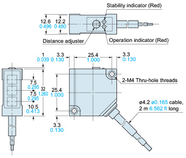
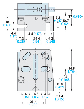
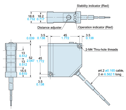
Dimensions
- Unit: mm in
MQ-W3□ MQ-WN3□
Sensor
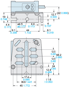
Assembly dimensions with attached mounting bracket
MQ-W20□ MQ-WN20□
Sensor
Assembly dimensions with attached mounting bracket
MQ-W70□ MQ-WN70□
Sensor
Assembly dimensions with attached mounting bracket
I/O Circuit and Wiring diagrams
I/O circuit diagram
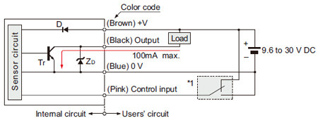
Symbols・・・
D:Reverse supply polarity protection diode
ZD:Surge absorption zener diode
Tr:NPN output transistor
Wiring diagram
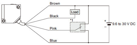
* 1: Selecting output operation by connecting control input wire (pink)
| Processing | Output operation |
|---|---|
| Connected to +V | Light-ON |
| Connected to 0 V | Dark-ON |
Sensing characteristics
*TYPICAL
40 mm 1.575 in Type
Sensing field
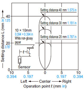
Correlation between sensing object size and sensing range
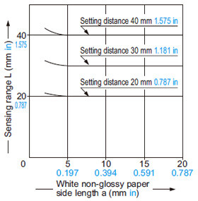
These curves show the characteristics with the maximum sensing range set to 40 mm1.575 in, 30 mm1.181 inand 20 mm0.787 in, with white non-glossy paper (10 × 10 mm0.394 × 0.394 in).
Correlation between material and sensing range
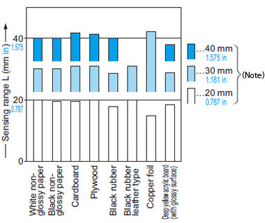
(Note)These bars indicate the sensing range with the respective objects when the distance adjuster is set to a sensing range of 40 mm1.575 in, 30 mm1.181 inand 20 mm0.787 inlong, respectively, with white non-glossy paper.(Sensing object size: 35 × 60 mm1.378 × 2.362 in.)
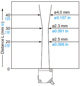
Emitted beam
200 mm 7.874 in Type
Sensing field
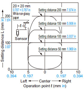
Correlation between sensing object size and sensing range
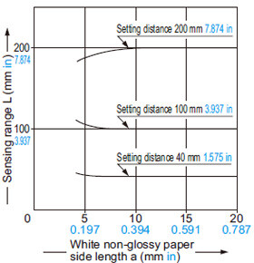
These curves show the characteristics with the maximum sensing range set to 200 mm7.874 in, 100 mm3.937 inand 40 mm1.575 in, with white non-glossy paper (20 × 20 mm0.787 × 0.787 in).
Correlation between material and sensing range
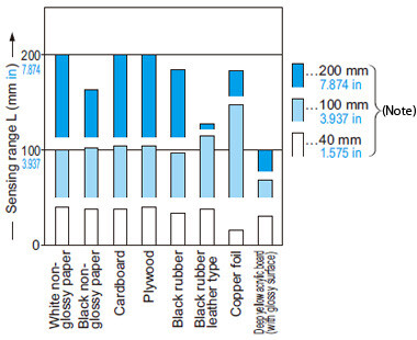
(Note)These bars indicate the sensing range with the respective objects when the distance adjuster is set to a sensing range of 200 mm7.874 in, 100 mm3.937 inand 40 mm1.575 inlong, respectively, with white non-glossy paper.(Sensing object size: 35 × 60 mm1.378 × 2.362 in.)
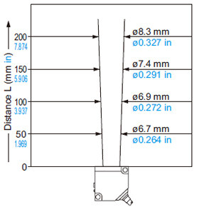
Emitted beam
700 mm 27.559 in Type
Sensing field
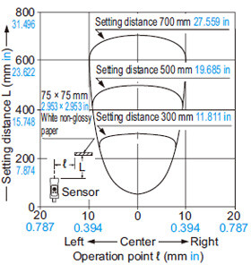
Correlation between sensing object size and sensing range
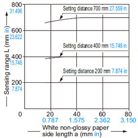
These curves show the characteristics with the maximum sensing range set to 700 mm27.559 in, 400 mm15.748 inand 200 mm7.874 in, with white non-glossy paper (75 × 75 mm2.953 × 2.953 in).
Correlation between material and sensing range
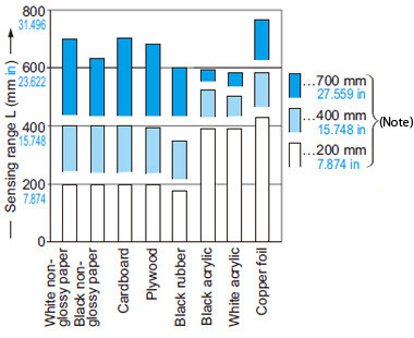
(Note)These bars indicate the sensing range with the respective objects when the distance adjuster is set to a sensing range of 700 mm27.559 in, 400 mm15.748 inand 200 mm7.874 inlong, respectively, with white non-glossy paper.(Sensing object size: 35 × 60 mm1.378 × 2.362 in.)
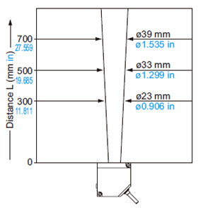
Emitted beam
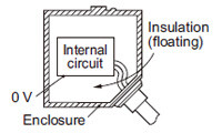
Case grounding method and insulation mounting bracket
- The MQ-W series has an internal circuit that is completely insulated from the enclosure (floating method).
- An exclusive insulation mounting bracket is available in order to improve the anti-noise quality in case there are devices that produce high-frequency noise close to the sensor and the place where the sensor is mounted is an electric conductor (such as metal). Please contact our office for details.
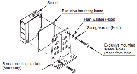
Note: Attached with the exclusive insulating board.
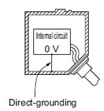
- Performing direct-grounding between the enclosure and circuit 0 V will improve the anti-noise quality.
- Contact our office if you would like to special-order the direct-grounding type that has the enclosure and circuit 0 V connected beforehand.
Others
- Do not use during the initial transient time (50 ms) after the power supply is switched on.