Basic Information
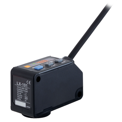
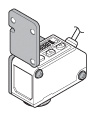
Introduction of the 3 LED mark sensor


UL : Recognition
Features
Can detect any mark!
Coaxial reflective optics and a sharp 1 x 5 mm 0.039 x 0.197 in spot enable high precision sensing. Stable detection of marks is possible.
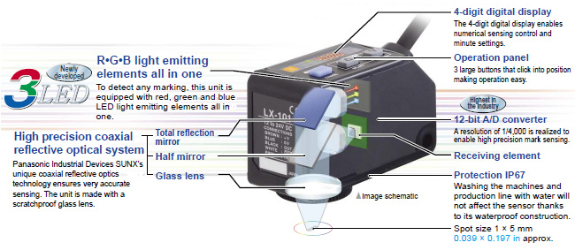
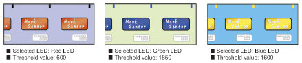
Automatic optimal LED selection function
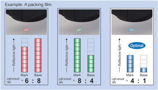
The 3 colors of the R・G・B LEDs are optimally selected according to the color combination. With the LX-100's Mark mode, the built-in "Automatic optimal LED selection function" automatically selects the LED for the largest contrast (S / N ratio) between the mark and base (non-mark area) to ensure optimal sensing. For more stable detection, the sensor makes selections according to the contrast and not according to the reflected light variation between the mark and base (non-mark area).
[The example on shown below deals with reflected light on packing film.
Great figures are indicated for the blue LED's light amount ratio and, for even more stable sensing, the blue LED effectuates this mark sensing.]
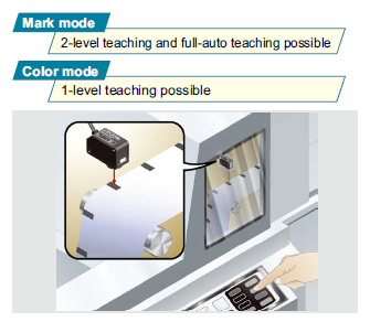
Two detection modes can be selected from to suit the application
■Mark mode [Ultra high-speed response]
This sensing mode automatically selects a single color from the 3 R・G・B LEDs to achieve an ultra quick 45 μs response time. The automatic optimal LED selection function automatically selects the LED that is most suitable for the sensing. This function is perfect for ultra quick sensing.
![Mark mode [Ultra high-speed response]](https://ap.industry.panasonic.com/hubfs/pid-corp/products/fasys/sensor/photoelectric/lx-100/images/pic06.jpg)
■Color mode [High precision discrimination]
All 3 R・G・B LEDs light up and high precision mark color discrimination occurs using the R・G・B reflective light ratio. This function enables effective detection of films with patterns around the area of the mark.
![Color mode [High precision discrimination]](https://ap.industry.panasonic.com/hubfs/pid-corp/products/fasys/sensor/photoelectric/lx-100/images/pic07.jpg)
* You can select the Mark mode or Color mode through key operation.
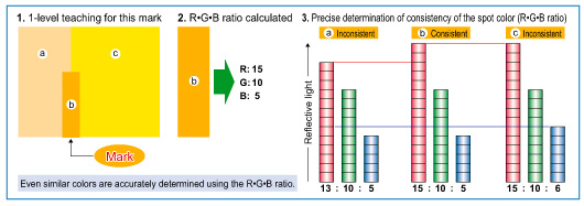
High precision mark color discrimination
The Color mode on the LX-100 series utilizes all 3 R・G・B LEDs to determine the R・G・B ratio of the mark color.
The built-in 12-bit A/D converter enables high precision 1/4,000-resolution judgments. The figure below is a graphic description of this process.
Its digital display makes settings easy! Numerical control of the settings is possible
The 4-digit digital display enables easy verification of received light from marks and base (non-mark area). Also, the threshold value can be controlled numerically enabling setting indication easily. Displaying the direct code enables settings verification. This function is handy for remote maintenance.
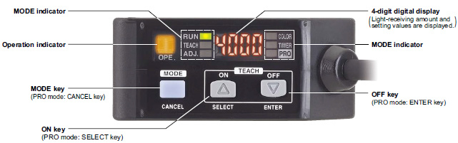
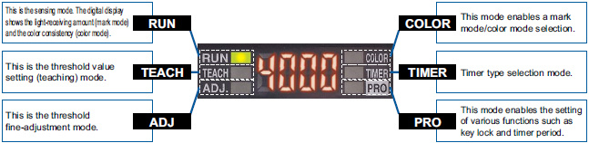
Even beginners can quickly master MODE NAVI operation
The sensor's basic operations are represented by 6 indicators (MODE NAVI). The user can check what mode the sensor is presently in with a quick glance making operation simple.
Sensing status digitally controllable
The sensing status, displayed numerically, can be verified at a glance. Also, the sensor settings for each type of packing film can be digitally indicated.
Direct codes enable settings verification at a glance
The settings for the LX-100 series sensors are displayed using a 4-digit direct code. Direct codes enable easy setting verification and maintenance by phone.

■Direct code table (D-Code)
The sensor setting modes can be verified by a 4-digit code (D-Code). The table below shows a list of all available codes.
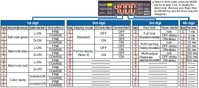
Notes:1) In Mark mode, L-ON / D-ON is automatically set in the sensor. For example, with 2-level teaching, press the ON key at the targeted mark and press the OFF key at the base (non-mark area). When doing so, the operator does not have to consider L-ON / D-ON.2) Sensing accuracy can be set to either FINE (standard) or COARSE.3) The percent display is only enabled in Mark mode.4) ECO mode is a function that reduces power consumption by turning off the digital display in the event that no button operations are made for a predetermined time (approx. 10 sec. or more) in RUN mode. Press any button to turn the digital display on again.5) The turn mode is a function that reverses the digital display making it easily to be viewed in the event that the sensor installation renders the display up-side-down.* Default setting: D-code = "0004".
Super simple teaching
■Press the ON button at the targeted mark.
Here is an example of the most basic setting method "2-level teaching".
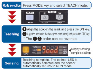
■External teaching possible
Teaching is possible through external input using an operation panel or touch panel even on hard-to-reach color mark sensors located inside an equipment.
Also, models can be interchanged easily.
■Other teaching methods
-Full-auto teaching:
In Mark mode, teaching is effective without stopping the sensing object.
-1-level teaching:
In Color mode, the color detected is aligned by the spot and teaching is effective.
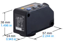
Compact design for significant space savings
High precision sensing and multiple functions are all packed in a compact W57 x D24 x H38 mm W2.244 x D0.945 x H1.496 in body.
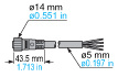
Cable and plug-in connector types are available depending on the equipment used.
These sensors can be easily introduced to existing facilities.
Key lock function
The key lock function enables input operation control that prevents mistaken changes in the sensor settings.
Other detailed settings include "RUN adjust", allowing threshold value adjustment only, and "RUN teaching", allowing teaching operation only.
If the sensor is set to "RUN adjust" or "RUN teaching", adjustment and teaching are possible having the sensor remained in RUN mode.
Order guide
Sensors
Mating cable is not supplied with the plug-in connector type. Please order it separately.
| Type | Appearance | Model No. | Output | Sensing range |
|---|---|---|---|---|
| Cable type |
| LX-101 | NPN open-collector transistor | 10 ±3mm 0.394 ±0.118 in |
| LX-101-P | PNP open-collector transistor | |||
| Plug-in connector type |
| LX-101-Z | NPN open-collector transistor | |
| LX-101-P-Z | PNP open-collector transistor |


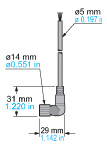
Mating cables for plug-in connector type sensor
Mating cable is not supplied with the plug-in connector type sensor. Please order it separately.
Mating cable is not supplied with the plug-in connector type sensor. Please order it separately.
| Type | Model No. | Description | |
|---|---|---|---|
| Straight | CN-24B-C2 | Length: 2 m 6.562 ft | 0.34 mm2 4-core cabtyre cable, with connector on one end Cable outer diameter: ø5 mm ø0.197 in |
| CN-24B-C5 | Length: 5 m 16.404 ft | ||
| Elbow | CN-24BL-C2 | Length: 2 m 6.562 ft | |
| CN-24BL-C5 | Length: 5 m 16.404 ft | ||
Mating cables for plug-in connector type sensor
CN-24B-C2 CN-24B-C5
CN-24BL-C2 CN-24BL-C5
Option
| Type | Model No. | Description |
|---|---|---|
| Sensor mounting bracket | MS-LX-1 | Mounting bracket made for LX-100 series applicable for various kinds of installations |
| MS-LX-2 |
Sensor mounting bracket
MS-LX-1
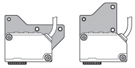
Two M4 (length 28 mm1.102 in) screws with washers are attached.
MS-LX-2
Two M4 (length 30 mm1.181 in) screws with washers are attached.
Specifications
| Type | Cable type | Plug-in connector type | |
|---|---|---|---|
| Model No. | NPN output | LX-101 | LX-101-Z |
| PNP output | LX-101-P | LX-101-P-Z | |
| CE marking directive compliance | EMC Directive, RoHS Directive | ||
| Sensing range | 10 ± 3 mm 0.394 ± 0.118 in | ||
| Spot size | 1 x 5 mm 0.039 x 0.197 in (at 10 mm 0.394 in setting distance) | ||
| Supply voltage | 12 to 24 V DC ± 10 % Ripple P-P 10 % or less | ||
| Current consumption | Normal mode: 750 mW or less (Current consumption 30 mA or less at 24 V supply voltage) ECO mode: 600 mW or less (Current consumption 25 mA or less at 24 V supply voltage) | ||
| Output 1 (OUT) | <NPN output type> NPN open-collector transistor ・Maximum sink current: 50 mA ・Applied voltage: 30 V DC or less (between output and 0 V) ・Residual voltage: 1.5 V or less (at 50 mA sink current) <PNP output type> PNP open-collector transistor ・Maximum source current: 50 mA ・Applied voltage: 30 V DC or less (between output and +V) ・Residual voltage: 1.5 V or less (at 50 mA source current) | <NPN output type> NPN open-collector transistor ・Maximum sink current: 100 mA ・Applied voltage: 30 V DC or less (between output and 0 V) ・Residual voltage: 1.5 V or less (at 100 mA sink current) <PNP output type> PNP open-collector transistor ・Maximum source current: 100 mA ・Applied voltage: 30 V DC or less (between output and +V) ・Residual voltage: 1.5 V or less (at 100 mA source current) | |
| Short-circuit protection | Incorporated | ||
| Output operation | Mark mode: Light-ON / Dark-ON (Auto-setting on teaching), Color mode: Consistent-ON / Inconsistent-ON (Setting on teaching) | ||
| Output 2 (OUT) | <NPN output type> NPN open-collector transistor ・Maximum sink current: 50 mA ・Applied voltage: 30 V DC or less (between output and 0 V) ・Residual voltage: 1.5 V or less (at 50 mA sink current) <PNP output type> PNP open-collector transistor ・Maximum source current: 50 mA ・Applied voltage: 30 V DC or less (between output and +V) ・Residual voltage: 1.5 V or less (at 50 mA source current) | - | |
| Short-circuit protection | Incorporated | - | |
| Output operation | Inverted operation of the output 1 | - | |
| Response time | Mark mode: 45 μs or less, Color mode: 150 μs or less | ||
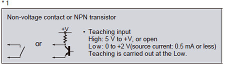
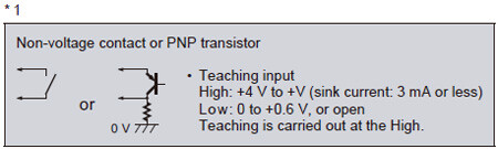
| Teaching input | <NPN output type> NPN non-contact input ・Signal condition: High... +5 V to +V, or open Low... 0 to +2 V (source current: 0.5 mA or less) ・Input impedance: 10 kΩ approx. <PNP output type> PNP non-contact input ・Signal condition: High... +4 V to +V (sink current: 3 mA or less) Low... 0 to +0.6 V, or open ・Input impedance: 10 kΩ approx. | ||
| Digital display | 4-digit red LED display | ||
| Sensitivity setting | Mark mode: 2-level teaching / Full-auto teaching, Color mode: 1-level teaching | ||
| Fine sensitivity adjustment function | Incorporated | ||
| Timer function | Incorporated with variable ON-delay / OFF-delay timer, switchable either effective or ineffective (Timer period: 1 to 500 ms, 9 levels variable) | ||
| Protection | IP67 (IEC) | ||
| Ambient temperature | -10 to +55 ℃ +14 to +131 ℉ (No dew condensation or icing allowed), Storage: -20 to +70 ℃ -4 to +158 ℉ | ||
| Ambient humidity | 35 to 85 % RH, Storage: 35 to 85 % RH | ||
| Ambient illuminance | Incandescent light: 3,000 or less lx at the light-receiving face | ||
| Voltage withstandability | 1,000 V AC for one min. between all supply terminals connected together and enclosure | ||
| Vibration resistance | 10 to 500 Hz frequency, 3 mm double amplitude or maximum acceleration 196 m/s2 in X, Y, and Z direction for 2 hours each | ||
| Shock resistance | 500 m/s2 acceleration (50 G approx.) in X, Y and Z directions three times each | ||
| Emitting element | Combined Red / Green / Blue LEDs (Peak emission wavelength: 640 nm 0.025 mil / 525 nm 0.021 mil / 470 nm 0.019 mil) | ||
| Material | Enclosure: PBT, Display cover: Polycarbonate, Operation buttons: Silicone rubber, Lens: Glass, Lens holder: Aluminum | ||
| Cable | 0.2 mm2 5-core cabtyre cable, 2 m 6.562 ft long | (Note 2) | |
| Cable extension | Extension up to total 100 m 328.084 ft is possible with 0.3 mm2, or more, cable. | ||
| Weight | Net weight: 120 g approx., Gross weight: 180 g approx. | Net weight: 55 g approx., Gross weight: 120 g approx. | |
| Accessory | M4 (length 30 mm 1.181 in) screw with washers: 2 pcs. | ||
Note 1 :Where measurement conditions have not been specified precisely, the conditions used were an ambient temperature of +23 ℃ +73.4 ℉ .
Note 2 :Mating cable is not supplied with the plug-in connector type. Please order it separately.
SPOT SIZE CHARACTERISTICS (TYPICAL)
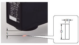
(Unit: mm in)
| Setting distance L (Note 1) | Spot size (Note 2) | |
|---|---|---|
| Width (W) | Length (D) | |
| 7 0.276 | 2.0 0.079 | 5.5 0.217 |
| 8 0.315 | 1.7 0.067 | 5.5 0.217 |
| 9 0.354 | 1.2 0.047 | 5.3 0.209 |
| 10 0.394 | 1.0 0.039 | 5.0 0.197 |
| 11 0.433 | 1.3 0.051 | 5.0 0.197 |
| 12 0.472 | 1.5 0.059 | 5.0 0.197 |
| 13 0.512 | 2.0 0.079 | 5.0 0.197 |
Notes:
1)Setting distance “L” represents the distance from the lens surface to the sensing object.
2)Examples only meant for use as a guideline.
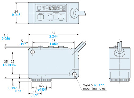
Dimensions
- Unit: mm in
LX-101 LX-101-P
Sensor
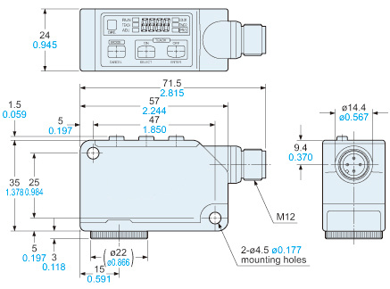
LX-101-Z LX-101-P-Z
Sensor
MS-LX-1
Sensor mounting bracket (Optional)
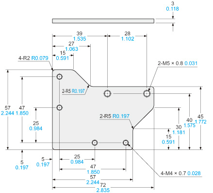
Material:Stainless steel (SUS)Two M4 (length 28 mm1.102 in) screws with washers are attached.
MS-LX-2
Sensor mounting bracket (Optional)
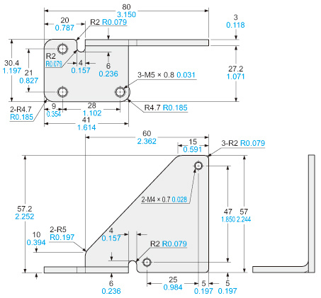
Material:Stainless steel (SUS)Two M4 (length 30 mm1.181 in) screws with washers are attached.
I/O Circuit and Wiring diagrams
I/O circuit diagram
NPN output type
LX-101(-Z)
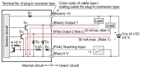
Notes:
1) The current of the plug-in connector type LX-101-Z is 100 mA max.
2) The output 2 is not incorporated to the plug-in connector type LX-101-Z.
Symbols・・・
D1, D2 : Reverse supply polarity protection diode
ZD1, ZD2: Surge absorption zener diode
Tr1, Tr2 : NPN output transistor
PNP output type
LX-101-P(-Z)
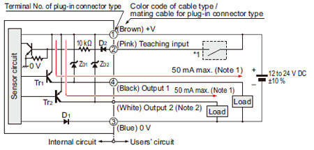
Notes:
1) The current of the plug-in connector type LX-101-P-Z is 100 mA max.
2) The output 2 is not incorporated to the plug-in connector type LX-101-P-Z.
Symbols・・・
D1, D2 : Reverse supply polarity protection diode
ZD1, ZD2: Surge absorption zener diode
Tr1, Tr2 : PNP output transistor
Connector pin layout of plug-in connector type
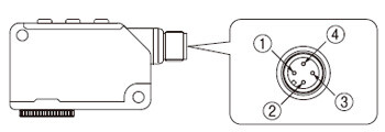
| Connector pin No. | Description |
|---|---|
| ① | +V |
| ② | Teaching input |
| ③ | 0 V |
| ④ | Output |
Mounting
- Care must be taken regarding the sensor mounting direction with respect to the object’s direction of movement.
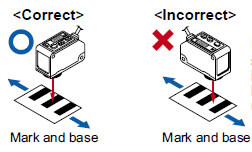
Do not make the sensor detect an object in this direction because it may cause unstable operation.
- With the optional sensor mounting bracket, the tightening torque should be 0.8 N·m or less.
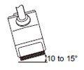
Sensing glossy object
- Objects with a glossy surface have a large amount of specular reflection particles that may destabilize sensing.
In such a case, by slightly tilting the sensor’s beam axis, this specular reflection can be reduced rendering sensing more stable.
- If the surface of the sensing object has a shine, mount the sensor inclining approx. 10 to 15 degrees against the sensing object.
Wiring
- Make sure to carry out wiring in the power supply off condition.
- Take care that wrong wiring will damage the sensor.
- Verify that the supply voltage variation is within the rating.
- Take care that if a voltage exceeding the rated range is applied, or if an AC power supply is directly connected, the sensor may get burnt or damaged.
- In case noise generating equipment (switching regulator, inverter motor, etc.) is used in the vicinity of this product, connect the frame ground (F.G.) terminal of the equipment to an actual ground.
- If power is supplied from a commercial switching regulator, ensure that the frame ground (F.G.) terminal of the power supply is connected to an actual ground.
- Do not use during the initial transient time (0.5 sec.) after the power supply is switched on.
- Take care that short-circuit of the load or wrong wiring may burn or damage the sensor.
- Do not run the wires together with high-voltage lines or power lines or put them in the same raceway. This can cause malfunction due to induction.
- Extension up to total 100 m is possible with 0.3 mm2, or more, cable. However, in order to reduce noise, make the wiring as short as possible.
Others
- This product has been developed / produced for industrial use only.
- Do not use during the initial transient time (0.5 sec.) after the power supply is switched on.
- Take care that the sensor is not directly exposed to fluorescent light from a rapid-starter lamp or a high frequency light device or sunlight etc., as it may affect the sensing performance.
- Do not touch the lens of the sensor by hand directly. If the lens becomes dirty, wipe it off with a soft cloth gently.
- When the inside lens is steamed up, unscrew the lens to get rid of the condensation.
- These sensors are only for indoor use.
- Do not use this sensor in places having excessive vapor, dust, etc., or where it may come in direct contact with water, or corrosive gas.
- Take care that the product does not come in contact with water, oil, grease, or organic solvents, such as, thinner, etc.
- Make sure that stress by forcible bend or pulling with 76 N, or more, force is not applied to the sensor cable joint.
- This sensor cannot be used in an environment containing inflammable or explosive gases.
- Never disassemble or modify the sensor.