Basic Information
User-friendly, high precision laser sensing!


UL/C-UL : Recognition (Excluding LS-403)
FDA : LS-H□F□ only
Features
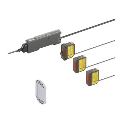
We offer 6 types of laser sensor heads for various applications

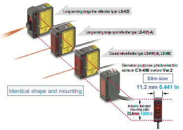
Industry standard mounting pitch
The mounting pitch for sensor heads is 25.4 mm 1.000 in, the same industry standard as the CX-400 series Ver.2 general purpose photoelectric sensors. Hence, existing mounting brackets can be used even when replacing general purpose sensors with laser sensors.
Easy and accurate adjustments
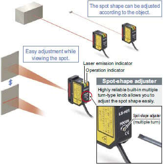
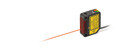
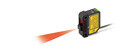
[Long sensing range spot reflective type] [Long sensing range line reflective type]
A spot-size adjuster is built into the back of the sensor head allowing the user to adjust the sensor easily while viewing the spot. The adjuster is adjustable with a screwdriver to avoid accidents during maintenance or any other time the sensors are handled.
Line-up of FDA / IEC / JIS Class 1 type [LS-H91(F)-A, LS-H21(F)-A]
Visible light spot using the Class 1 type. This makes beam axis alignment much easier.
![Line-up of FDA / IEC / JIS Class 1 type [LS-H91(F)-A, LS-H21(F)-A]](https://ap.industry.panasonic.com/hubfs/pid-corp/products/fasys/sensor/photoelectric/ls/images/pic12.jpg)
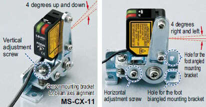
Sensor mounting bracket for beam axis alignment is available [MS-CX-11]
It is possible to make a minor adjustment for the bracket by 4 degrees up, down, right or left, even after setting up the sensor. The bracket can be mounted in both longitudinal and lateral directions.
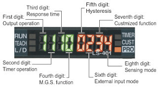
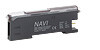
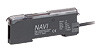
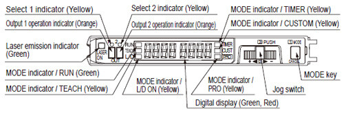
Easy setting, dual display
Equipped with 2 large 4-digit digital displays. While checking the current incident light intensity (red display), the optimal threshold value (green display) can be set easily.
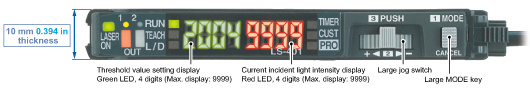
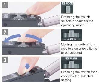
2 switches enable simple operation
Only two switches, the large MODE key and the large jog switch, are required for operation.
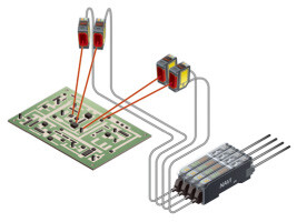
Wiring and space saving
The quick-connection cables enable reductions in wiring.
(connector type)
The quick-connection cables enable reductions in wiring. (connector type)
The connections and man-hours for the relay terminal setup can be reduced and valuable space is saved. Also, LS-400 series amplifiers can of course be connected side-by-side with a connector type amplifier of FX-500/FX-300 series digital fiber sensors or DPS-400 series digital pressure sensors.
Note :Because the transmission method varies depending on the amplifiers, check the instruction manual for the amplifiers when connecting them.

New release of type with upper communication functions to facilitate preventive maintenance!
[LS-403]
Network communication possible
Can connect to Open Network CC-Link IE Field / CC-Link / EtherCAT via Communication Unit for Open Network SC-GU3 series. Monitoring and various settings can be done from PLC, PC, etc.
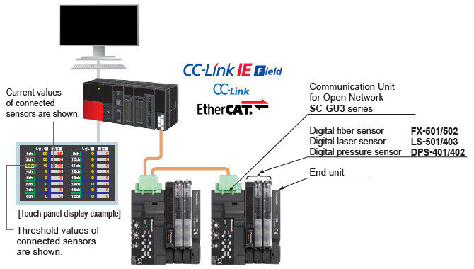
*CC-Link and CC-Link IE Field are a registered trademark of Mitsubishi Electric Corporation.
EtherCAT is a registered trademark of Beckhoff Automation GmbH.
*Refer to SC-GU3 series.
Threshold tracking function saves maintenance time
This function seeks changes in the light emitting amount resulting from changes in the environment over long periods (such as dust levels), so that the incident light intensity can be checked at desired intervals and the threshold values can be reset automatically. This helps to reduce the man-hours for maintenance.

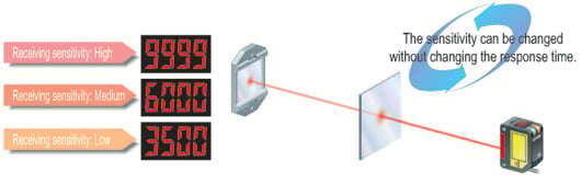
Accurately sense the minutest variations (M.G.S. function)
When sensing at close range or when the target objects are transparent or minute, adjust the sensor receiving sensitivity to one of 3 levels (U-LG mode: 4 levels) for the optimal setting. In addition, changing the receiving sensitivity will not effect the response time.
4 new modes enabling wide array of sensing
[Hysteresis mode]
By adjusting the hysteresis, convexo-concave parts of uneven objects can be cancelled enabling more stable sensing.

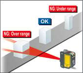
[Window comparator mode]
The sensor judges any object outside the range of incident light intensity established by two set threshold values.
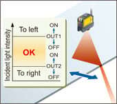
[2 independent output modes]
By combining two outputs, a wide array of control is possible, allowing you to detect meandering objects, for example.
[Differential sensing mode] Only rapid changes in light received are detected, which enable the edge of glass, etc. to be detected accurately. Optimal for positioning.
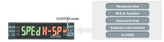
MODE NAVI customized function
Frequently used functions such as response time, M.G.S. function, data bank load, emission halt function and D-CODE values can be stored in CUSTOM mode. The settings can also be changed easily.
Emission halt function
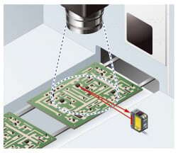
If you do not want to place a laser spot in the visual range of the image processor, you can stop the laser radiation using the emission halt signal from the external input.
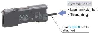
Cable type allows external input
The LS-401-C2 cable-type amplifier is equipped with an external input wire (5-core). It is ideal to use the laser sensor at places where external teaching or laser light emission halting is to be carried out, or at places where the laser sensor is to be used separately.
Interference prevention function
The automatic interference prevention function prevents against interference among up to 4 sensors.
Setting conditions viewed at a glance (D-CODE)
The amplifier setting is shown in an 8-digit code. This is handy for remote indications and follow-ups.
Applications
Detecting objects with a complex shape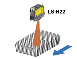
Its linear sensing area enables more stable detection of objects with complex shapes.
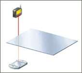
Detecting the remaining amount of sheet rolls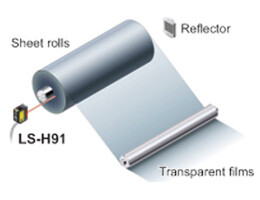
The coaxial retroreflective sensor with a spot diameter of approx. ø1 mm ø0.039 in (at a 1 m 3.281 ft sensing distance) can measure amounts remaining on sheet rolls with high precision.
Detecting electronic component pins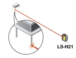
Because its spot shape can be adjusted in accordance with the object, it can be easily set to detect even the minutest object from a remote location.
Order guide
Sensor heads
| Type | Appearance | Model No. | Conforming standards | Sensing range | ||
|---|---|---|---|---|---|---|
| Coaxial retroreflective | Class 2 |
| LS-H92 | IEC / EN / JIS / GB / KS | U-LG : 0.2 to 30 m 0.656 to 98.425 ft (Note 3) STD : 0.2 to 20 m 0.656 to 65.617 ft (Note 3) FAST : 0.2 to 10 m 0.656 to 32.808 ft (Note 3) H-SP : 0.2 to 10 m 0.656 to 32.808 ft (Note 3) | |
| LS-H92F (Note 1) | FDA / IEC / EN / JIS | |||||
| LS-H91 | IEC / EN / JIS / GB / KS | U-LG : 0.1 to 7 m 0.328 to 22.966 ft (Note 3) STD : 0.1 to 5 m 0.328 to 16.404 ft (Note 3) FAST : 0.1 to 3 m 0.328 to 9.843 ft (Note 3) H-SP : 0.1 to 3 m 0.328 to 9.843 ft (Note 3) | ||||
| LS-H91F (Note 1) | FDA / IEC / EN / JIS | |||||
| Class 1 | LS-H91-A | IEC / EN / JIS / GB / KS | U-LG : 0.1 to 5 m 0.328 to 16.404 ft (Note 3) STD : 0.1 to 3 m 0.328 to 9.843 ft (Note 3) FAST : 0.1 to 1 m 0.328 to 3.281 ft (Note 3) H-SP : 0.1 to 1 m 0.328 to 3.281 ft (Note 3) | |||
| LS-H91F-A (Note 1) | FDA / IEC / EN / JIS | |||||
| Diffuse reflective | Long sensing range spot reflective | Class 2 |
| LS-H21 | IEC / EN / JIS / GB / KS | U-LG : 30 to 1,000 mm 1.181 to 39.370 in STD : 30 to 500 mm 1.181 to 19.685 in FAST : 30 to 300 mm 1.181 to 11.811 in H-SP : 30 to 300 mm 1.181 to 11.811 in |
| LS-H21F (Note 1) | FDA / IEC / EN / JIS | |||||
| Class 1 | LS-H21-A | IEC / EN / JIS / GB / KS | U-LG : 30 to 500 mm 1.181 to 19.685 in STD : 30 to 250 mm 1.181 to 9.843 in FAST : 30 to 150 mm 1.181 to 5.906 in H-SP : 30 to 150 mm 1.181 to 5.906 in | |||
| LS-H21F-A (Note 1) | FDA / IEC / EN / JIS | |||||
| Long sensing range line reflective | Class 2 |
| LS-H22 (Note 2) | IEC / EN / JIS / GB / KS | U-LG : 30 to 1,000 mm 1.181 to 39.370 in STD : 30 to 500 mm 1.181 to 19.685 in FAST : 30 to 300 mm 1.181 to 11.811 in H-SP : 30 to 300 mm 1.181 to 11.811 in | |
| LS-H22F (Note 1,2) | FDA / IEC / EN / JIS | |||||
Note 1 :This product complies with the FDA regulations (FDA 21 CFR 1040.10 and 1040.11) in accordance with FDA Laser Notice No. 56, except for complying with IEC 60825-1 Ed. 3.
Note 2 :LS-H22(F) is the model No. for LS-H21(F) long sensing range spot reflective type sensor head combined with the LS-MR1 lens attachment for line reflective type sensor head. Hence, LS-H21(F) appears on the sensor head itself.
Note 3 :The sensing range is the value for the RF-330 [RF-230 for the LS-H92(F)] reflector. In addition, the sensing range is the possible setting range for the reflector. The sensor can detect an object less than 0.1 m 0.328 ft [LS-H92(F): 0.2 m 0.656 ft] away. Note that if there are white papers or specular objects near the sensor head, reflected light from these objects may be received. In such cases, use the M.G.S. function of the amplifier unit to change the response time or incident light sensitivity.
5 m 16.404 ft cable length type
5 m 16.404 ft cable length type (standard: 2 m 6.562 ft ) is also available.
When ordering this type, suffix "-C5" to the model No.
LS-H91-C5, LS-H91-A-C5, LS-H21-C5, LS-H22-C5
| Standard type | 5 m 16.404 ft cable length type |
|---|---|
| LS-H91 | LS-H91-C5 |
| LS-H91-A | LS-H91-A-C5 |
| LS-H21 | LS-H21-C5 |
| LS-H22 | LS-H22-C5 |
Package without reflector
The LS-H91(F), LS-H91(F)-A and LS-H92(F) are also available without the reflector (RF-330 or RF-230).
When ordering this type, suffix "-Y" to the model No.
LS-H92-Y, LS-H92F-Y, LS-H91-Y, LS-H91F-Y, LS-H91-A-Y, LS-H91F-A-Y
| Standard type | Package without reflector |
|---|---|
| LS-H92 | LS-H92-Y |
| LS-H92F | LS-H92F-Y |
| LS-H91 | LS-H91-Y |
| LS-H91F | LS-H91F-Y |
| LS-H91-A | LS-H91-A-Y |
| LS-H91F-A | LS-H91F-A-Y |
Amplifiers
| Type | Appearance | Model No. | Output | Connection method | |
|---|---|---|---|---|---|
| Connector type |
| LS-401 | NPN open-collector transistor two outputs | Use quick-connection cable (4-core) (optional) | |
| LS-401P | PNP open-collector transistor two outputs | ||||
| With upper communication function (Note 1) | LS-403 | NPN open-collector transistor two outputs | |||
| Cable type (With external input) |
| LS-401-C2 | NPN open-collector transistor two outputs | 2 m 6.562 ft cabtyre cable (5-core) included Cable outer diameter: ø3.7 mm ø0.146 in | |
| LS-401P-C2 | PNP open-collector transistor two outputs | ||||
Note 1 :For upper communication, a communication unit for open network SC-GU3 series is needed separately. Refer to SC-GU3 series.
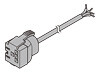
Quick-connection cables
Quick-connection cable is not supplied with the connector type amplifier. Please order it separately.
| Type | Appearance | Model No. | Description | |
|---|---|---|---|---|
| Main cable (4-core) |
| CN-74-C1 | Length: 1 m 3.281 ft | 0.2 mm2 4-core cabtyre cable, with connector on one end Cable outer diameter: ø3.3 mm ø0.130 in |
| CN-74-C2 | Length: 2 m 6.562 ft | |||
| CN-74-C5 | Length: 5 m 16.404 ft | |||
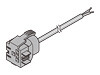
| Sub cable (2-core) |
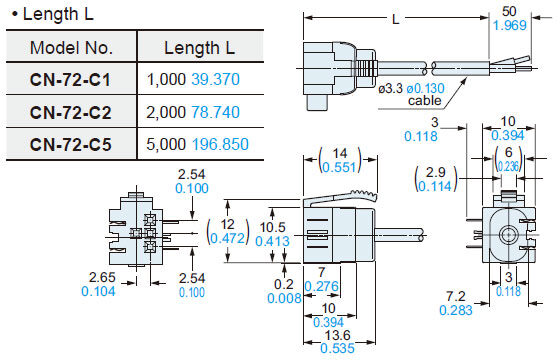
| CN-72-C1 | Length: 1 m 3.281 ft | 0.2 mm2 2-core cabtyre cable, with connector on one end Cable outer diameter: ø3.3 mm ø0.130 in |
| CN-72-C2 | Length: 2 m 6.562 ft | |||
| CN-72-C5 | Length: 5 m 16.404 ft | |||
(Note):The material of Quick-connection cable will be changed from production in March 2013, as soon as the previous ones are shipped out.
・Conductor cross-sectional area has been changed from 0.15mm2 to 0.2mm2.
・Sheath diameter has been changed from ø3.0mm to ø3.3mm.
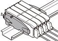
End plates
End plates are not supplied with the amplifier. Please order them separately when the amplifiers are mounted in cascade.
| Type | Model No. | Description |
|---|---|---|
| MS-DIN-E | When cascading multiple amplifiers, or when it moves depending on the way it is installed on a DIN rail, these end plates clamp amplifiers into place on both sides. Make sure to use end plates when cascading multiple amplifiers together. [ Two pcs. per set ] |
Accessories
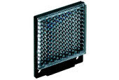
RF-330(Reflector)
CN-EP1(Connector for amplifier)5 pcs. per set (Note)
Note:One is attached to each sensor head according to standard.
LS-MR1(Lens attachment for line reflective type)
RF-230(Reflector)
Note: LS-H92(F) only
Option
| Designation | Model No. | Description | ||
|---|---|---|---|---|
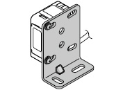
| Sensor head mounting bracket | MS-CX-1 | Foot angled mounting bracket | ||
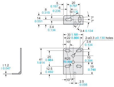
| MS-CX-2 | Foot biangled mounting bracket Flat mounting possible to avoid obstructions caused by the height of the sensor. | |||
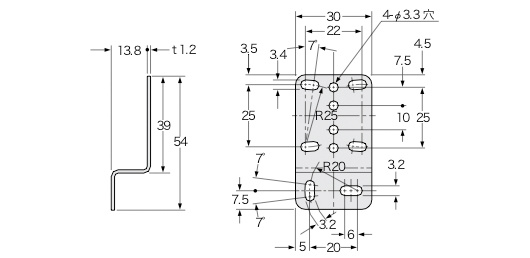
| MS-CX-3 | Back angled mounting bracket | |||
| MS-CX-4 | Protective mounting bracket Protects sensors preventing beam axis displacement due to shocks. | |||
| Sensor mounting bracket for beam axis alignment | MS-CX-11 | Mounting bracket that makes fine beam axis alignment possible after setting the sensor head. Adjustment angle: up and down, right and left: 4 degrees Mounting directions: two directions, vertical and horizontal | ||
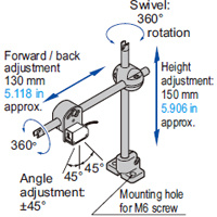
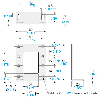
| Universal sensor mounting stand (Note 1) | MS-AJ1 | Horizontal mounting type | Basic assembly | |
| MS-AJ2 | Vertical mounting type | |||
| MS-AJ1-A | Horizontal mounting type | Lateral arm assembly | ||
| MS-AJ2-A | Vertical mounting type | |||
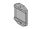
| Amplifier mounting bracket | MS-DIN-2 | Mounting bracket for amplifier | ||
| Reflector mounting bracket | MS-RF23 | Mounting bracket for RF-230 | ||
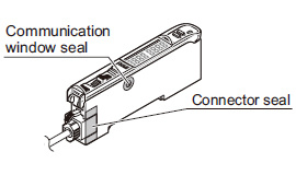
| Amplifier protection seal | FX-MB1 | 10 sets of 2 communication window seals and 1 connector seal Communication window seal: It prevents malfunction due to transmission signal from another amplifier, as well as, prevents effect on another amplifier. Connector seal: It prevents contact of any metal, etc., with the pins of the quick-connection cable. | ||
| Reflector | RF-310 | For coaxial retroreflective type Compact reflector | Sensing range (U-LG mode) ・LS-H91(F): 0.1 to 7 m 0.328 to 22.966 ft ・LS-H91(F)-A: 0.1 to 5 m 0.328 to 16.404 ft | |
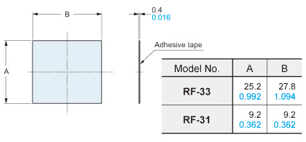
| Reflective tape | RF-33 | For coaxial retroreflective type Size: 25.2 x 27.8 x t 0.4 mm 25.2 x 27.8 x t 0.4 mm | ||
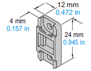
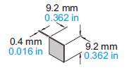
| RF-31 | For coaxial retroreflective type Size: 9.2 x 9.2 x t0.4mm 0.362 x 0.362 x t 0.016 in | |||
| Bank selection unit (Note 2) | FX-CH | NPN input type | Setting for up to 16 laser sensors can be changed at once by means of external signals. | |
| FX-CH-P | PNP input type | |||
Note 1 :Refer to the universal sensor mounting stand MS-AJ for details.
Note 2 :Refer to the bank selection unit FX-CH for details.
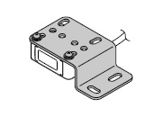
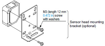
Sensor head mounting bracket
MS-CX-1
Two M3 (length 12 mm0.472 in) screws with washers are attached.
MS-CX-2
Two M3 (length 12 mm0.472 in) screws with washers are attached.
MS-CX-3
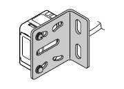
Two M3 (length 12 mm0.472 in) screws with washers are attached.
MS-CX-4
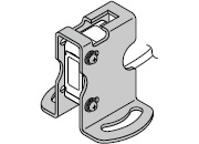
Two M3 (length 12 mm0.472 in) screws with washers are attached.
Sensor mounting bracket for beam axis alignment
MS-CX-11
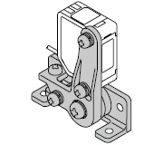
Two M3 (length 14 mm0.551 in) screws with washers are attached.
Amplifier mounting bracket
MS-DIN-2
Reflector mounting bracket
MS-RF23
Two M4 (length 10 mm0.394 in) screws with washers are attached.
Amplifier protection seal
FX-MB1
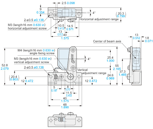
Universal sensor mounting stand
MS-AJ1

MS-AJ1-A
With the lateral arm, the sensor can sense from above a production line.
MS-AJ2

MS-AJ2-A

With the lateral arm, the sensor can sense from above a production line.
Bank selection unit
FX-CH(-P)
Reflector
RF-310
Reflective tape
RF-33

RF-31
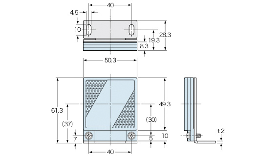
Dimensions
- Unit: mm in
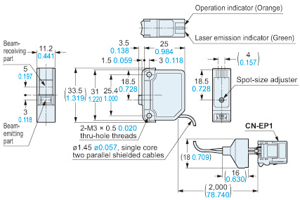
LS-H91(-A) LS-H91F(-A)
Sensor head

LS-H92 LS-H92F
Sensor head
LS-H21(-A) LS-H21F(-A)
Sensor head

LS-H22 LS-H22F
Sensor head
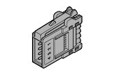
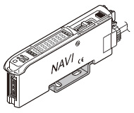
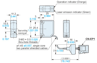
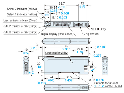
LS-401 LS-401P LS-403
Amplifier
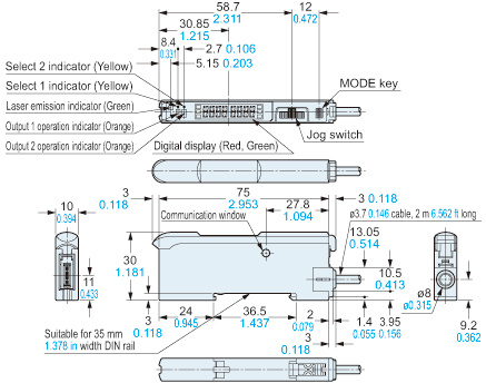
LS-401-C2 LS-401P-C2
Amplifier
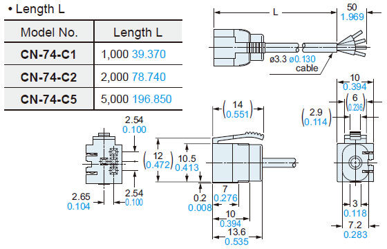
CN-74-C1 CN-74-C2 CN-74-C5
Main cable (Optional)
Length L
CN-72-C1 CN-72-C2 CN-72-C5
Sub cable (Optional)
Length L
MS-DIN-E
End plate (Optional)
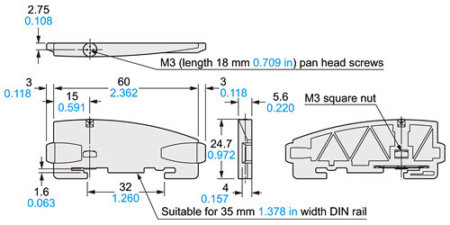
Material: Polycarbonate
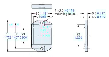
RF-230
Reflector [Accessory for LS-H92(F)]
Material: Acrylic (Reflector)ABS (Base)
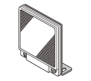
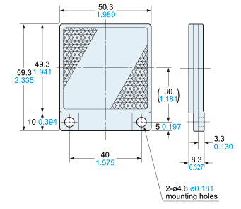
RF-330
Reflector (Accessory for LS-H91□)
Material: Acrylic (Reflector)ABS (Base)
RF-310
Reflector (Optional)
Material: Acrylic (Reflector)ABS (Base)
RF-33 RF-31
Reflective tape (Optional)
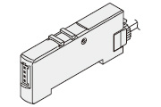
MS-DIN-2
Amplifier mounting bracket (Optional)

Material:Cold rolled carbon steel (SPCC)(Uni-chrome plated)
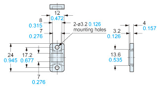
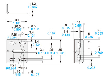
MS-CX-1
Sensor head mounting bracket (Optional)
Material: Stainless steel (SUS304)Two M3 (length 12 mm0.472 in) screws with washers are attached.
MS-CX-2
Sensor head mounting bracket (Optional)
Material:Stainless steel (SUS304) Two M3 (length 12 mm0.472 in) screws with washers are attached.
MS-CX-3
Sensor head mounting bracket (Optional)
Material:Stainless steel (SUS304)Two M3 (length 12 mm0.472 in) screws with washers are attached.
MS-CX-4
Sensor head mounting bracket (Optional)
Material: Stainless steel (SUS304)Two M3 (length 12 mm0.472 in)screws with washers are attached.
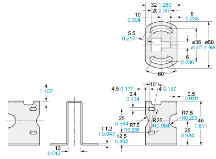
MS-CX-11
Sensor mounting bracket for beam axis alignment (Optional)
Material: Zinc die-castTwo M3 (length 14 mm0.551 in)screws with washers are attached.
MS-RF23
Reflector mounting bracket for RF-230 (Optional)
Material: Cold rolled carbon steel (SPCC)(Uni-chrome plated)Two M4 (length 10 mm0.394 in) screws with washers are attached.
Assembly dimensions
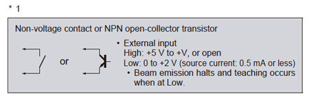
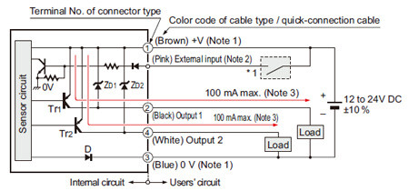
I/O Circuit and Wiring diagrams
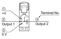
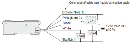
NPN output type
LS-401(-C2 ) LS-403
I/O circuit diagram
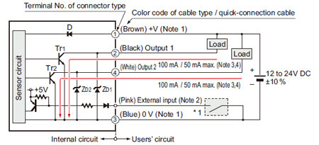
Notes:
1)The quick-connection sub cable does not have +V (brown) and 0 V (blue).The power is supplied from the connector of the main cable.
2)Connector type LS-401/403 does not incorporate the external input.
3)LS-401(-C2) is 100 mA max, however, LS-401(-C2) is 50 mA max.
if 5 to 8 amplifiers are connected in cascade, and 25 mA max. if 9 to 16 amplifiers are connected in cascade.
4)LS-403 is 50 mA max, however, it is 25 mA max. if 5 to 16 amplifiers are connected in cascade.
Symbols・・・
D: Reverse supply polarity protection diode
ZD1, ZD2: Surge absorption zener diode
Tr1, Tr2: NPN output transistor
Wiring diagram
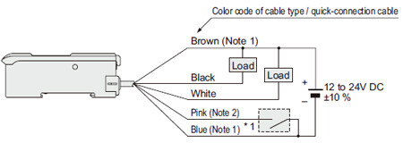
Notes:
1)The quick-connection sub cable does not have brown lead wire and blue lead wire.
The power is supplied from the connector of the main cable.
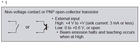
2)The quick-connection cable does not have a pink lead wire.
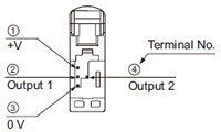
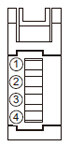
Terminal layout of connector type
* Connector for amplifier (CN-EP1) pin position
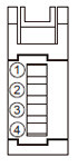
| Terminal No. | Connection cable | |
|---|---|---|
| ① | Conductor core wire: Brown | Cable color: Gray |
| ② | Shield wire | |
| ③ | Conductor core wire: Yellow | Cable color: Black |
| ④ | Shield wire | |
PNP output type
LS-401P(-C2)
I/O circuit diagram
Notes:
1)The quick-connection sub cable does not have +V (brown) and 0 V (blue).
The power is supplied from the connector of the main cable.
2)Connector type LS-401P does not incorporate the external input.
3)LS-401P is 50 mA max. if 5 to 8 amplifiers are connected in cascade, and 25 mA max. if 9 to 16 amplifiers are connected in cascade.
Symbols・・・
D: Reverse supply polarity protection diode
ZD1, ZD2: Surge absorption zener diode
Tr1, Tr2: PNP output transistor
Wiring diagram
Notes:
1)The quick-connection sub cable does not have brown lead wire and blue lead wire.
The power is supplied from the connector of the main cable.
2)The quick-connection cable does not have a pink lead wire.
Terminal layout of connector type
* Connector for amplifier (CN-EP1) pin position
| Terminal No. | Connection cable | |
|---|---|---|
| ① | Conductor core wire: Brown | Cable color: Gray |
| ② | Shield wire | |
| ③ | Conductor core wire: Yellow | Cable color: Black |
| ④ | Shield wire | |
- This product is a class 2 (LS-H□(F)-A is class 1 ) laser product according to IEC/EN/JIS/GB/KS standards and FDA regulations*.
- Avoid observing beams continuously, particularly in a dark surrounding environment.
- Do not look at beams using an optical device such as an optical telephoto system.
- The following label is affixed to this product. Handle the product according to the instruction given on the label.

In addition, each product comes with a label according to the standards it complies with.
If necessary, please use it by pasting it on or near the product.
Note) Do not place any other labels over the FDA certification/identification label.


* This product complies with the FDA regulations (FDA 21 CFR 1040.10 and 1040.11) in accordance with FDA Laser Notice No. 56, except for complying with IEC 60825-1 Ed. 3.
Safety standards for laser beam products
- For the purpose of preventing any injury which may occur to the user by the use of the laser product in advance, the following standards have been established by the IEC Standards, EN Standards, JIS Standards, GB Standards, KS Standards and FDA Regulations.
IEC : IEC 60825-1:2014
EN : EN 60825-1:2014/A11:2021
JIS : JIS C 6802:2014
GB : GB 7247.1-2012
KS : KS C IEC 60825-1:2014
FDA : PART 1040.10, 1040.11(Laser Notice No.56 applied)
These standards classifies laser products according to the level of hazard and provide the safety measures for respective classes.Based on the above standards, LS-H□(F) series is classified as a Class 2 laser product. LS-H□(F)-A series is classified as a Class 1 laser product.
| Classification | Description |
|---|---|
| Class 1 | Lasers that are safe under reasonably foreseeable conditions of operation, including the use of optical instruments for intrabeam viewing. |
| Class 2 | Lasers that emit visible radiation in the wavelength range from 400 nm to 700 nm where eye protection is normally afforded by aversion responses, including the blink reflex. This reaction may be expected to provide adequate protection under reasonably foreseeable conditions of operation including the use of optical instruments for intrabeam viewing. |
Note: When an unexpected failure occurs, dangerous radiation may be generated. Therefore, pay special attention to safety.
Safe use of laser products
- For the purpose of preventing users from suffering injuries by laser products, each standard stipulates (Safety of laser products). Kindly check the standards before use.
Cautions when connecting amplifiers in cascade
- Refer to connecting conditions written below when connecting amplifiers in cascade.
- When amplifiers are installed, refer to “Cautions on communication function” and use communication function.
Connecting conditions
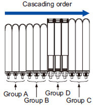
| Group A | LS-401(P)(-C2), FX-301(P):Previous version unit (Note 1),FX-301G(P)/B(P)/H(P), FX-41□(P) |
|---|---|
| Group B | FX-301(P): Updated version unit (Note 1),FX-301(P)-C1, FX-305(P) (Note 2) |
| Group C | LS-403, DPS-400 series,SC-T1JA |
| Group D | FX-500 series |
Notes:
1)The previous version unit is manufactured before June 2004.
The updated version unit is manufactured after June 2004.
2)Be sure to install FX-305 behind FX-301.
Cautions on communication function
| Copy function / channel bank function (when communicating) | Conditions when using SC-GU2-C | Interference prevention function |
|---|---|---|
| Each group should be cascaded in a lump. When group A, group B and group C are connected together in cascade, as for the products that are located between different groups, put the amplifier protection seal (FX-MB1 optional) on the amplifier communication window of each corresponding product. Interference prevention function cannot be used if amplifier protection seal is put on the amplifier communication window. Choose one from copy function / channel bank function (communication) or interference prevention function to be used. | [Group A] It cannot communicate with master. [Group B, Group C] They can communicate with master. When group B and group C are connected together in cascade, be sure that group B is located on the left side of group C. | Each group should be cascaded in a lump. When group A, group B and group C are connected together in cascade, refer to the connecting conditions for connecting. (Copy function cannot be used.) |
| When not using group A, copy function / channel bank function (communication) and interference prevention function can be used without putting on the amplifier protection seal. (Follow the connecting conditions when connecting.) |
Part description (Amplifier)
Spot-shape adjuster (Only for LS-H21□, LS-H22□)
- The diffuse reflective type LS-H21□ and LS-H22□ incorporate the spot-shape adjuster to adjust the shape of spots.
| Spot-shape adjuster | Description |
|---|---|
| Turn the spot-shape adjuster clockwise or counter-clockwise to adjust the spot shape at your desired detecting distance. However, if the adjuster is turned too far, it may be damaged. |

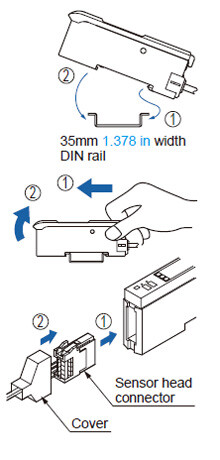
Mounting
Amplifier
<How to mount the amplifier>
①Fit the rear part of the mounting section of the amplifier on a 35 mm 1.378 in width DIN rail.
②Press down the rear part of the mounting section of the unit on the 35 mm 1.378 in width DIN rail and fit the front part of the mounting section to the DIN rail.
<How to remove the amplifier>
①Push the amplifier forward.
②Lift up the front part of the amplifier to remove it.
Note:Be careful. If the front part is lifted without pushing the amplifier forward, the hook on the rear portion of the mounting section is likely to break.
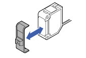
<How to mount the sensor head>
①Insert the sensor head connector into the inlet until it clicks.
②Fit the cover to the connector.
Sensor head
- The tightening torque should be 0.5 N·m or less.
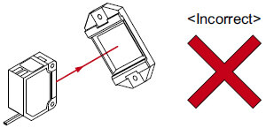
- When placing the sensor head horizontally or vertically, the reflector must also be positioned horizontally or vertically as shown in Fig. 1 below.
If the sensor head is placed horizontally or vertically but the reflector is leaned as shown in Fig. 2 below, the reflection amount will decrease, which may cause unstable detection.
Fig. 1 Proper positioning
When placing the sensor head horizontally or vertically, the reflector shall also be positioned horizontally or vertically.
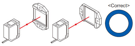
Fig. 2 Improper positioning
When placing the sensor head horizontally or vertically, but the reflector is leaned.
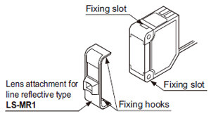
Lens attachment for line reflective type (LS-MR1)
Removing method
①Insert a screwdriver into the fixing slot located at the top of sensor head.
②Tilt the screwdriver inserted in Step ① to remove LS-MR1.
Mounting method
- The lens attachment for line reflective type LS-MR1 mounted in the long sensing range line reflective type LS-H22□ is removable.
When LS-H22□ is used without LS-MR1, it will provide the equivalent performance to the long sensing range spot reflective type LS-H21□. In addition, the optional LS-MR1 can be attached to LS-H21□ to obtain the performance equivalent to LS-H22□. - Keep the lens clean of dust, dirt, water, oil, grease, etc.
- Do not apply any excessive force to LS-MR1.
Such force may cause damage.
①The size of upper fixing hook of LS-MR1 is not same as the lower fixing hook. After identifying the upper and lower fixing hooks, insert LS-MR1 upper fixing hook into the fixing slot at the top of sensor head and then insert LS-MR1 lower fixing hook into the fixing slot at the bottom of sensor head.
②After mounting, check that LS-MR1 is properly fixed to the sensor head.
Wiring
- Make sure that the power supply is off while wiring.
- Verify that the supply voltage variation is within the rating.
- Take care that if a voltage exceeding the rated range is applied, or if an AC power supply is directly connected, the sensor may get burnt or damaged.
- Take care that short-circuit or wrong wiring of the load may burn or damage the sensor.
- Do not run the wires together with high-voltage lines or power lines or put them in the same raceway. This can cause malfunction due to induction.
- Ensure that an isolation transformer is utilized for the DC power supply. If an auto transformer is utilized, the main amplifier or power supply may be damaged.
- Make sure to use the optional quick-connection cable for the connection of the amplifier [connector type LS-401(P) / LS-403]. Extension up to total 100 m 328.084 ft is possible with 0.3 mm2, or more,cable. However, in order to reduce noise, make the wiring as short as possible.
Others
- This product has been developed / produced for industrial use only.
- Do not use during the initial transient time (0.5 sec. approx.) after the power supply is switched on.
- Because the sensitivity is higher in U-LG mode than in other modes, it can be more easily affected by extraneous noise.
Check the operating environment before use. - These sensors are only for indoor use.
- Avoid dust, dirt, and steam.
- Take care that the product does not come in direct contact with water, oil, grease, or organic solvents, such as, thinner, etc.
- This sensor cannot be used in an environment containing inflammable or explosive gasses.
- Never disassemble or modify the sensor.