Basic Information
Reliable liquid level detection with amplifier built-in low-priced sensor


CE : EMC Directive
UKCA : EMC Regulations
Features
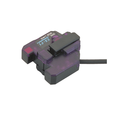
Space-saving amplifier built-in type
EX-F1 amplifier built-in sensor saves space as there is no need to install a separate amplifier.
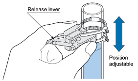
Easily mountable and adjustable
Just attach it on a pipe with the tying bands. The position can be easily changed with the release lever even after mounting, so that there is no need to cut the tying bands.
Low price
EX-F1 is very cost-effective.
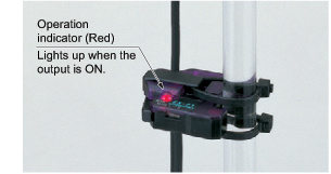
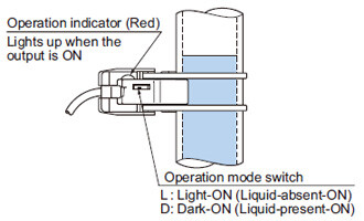
Easy to check operation Indicator
The operation can be checked at a glance from different directions.
Operation mode switch
Either Light-ON or Dark-ON can be selected by a switch. This is useful to check the operation during installation because it forces the output to be turned ON or OFF even without the liquid being inside the pipe.
Applications
Detecting liquid level in a tank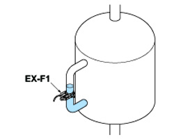
Order guide
| Type | Appearance | Sensing object | Applicable pipe diameter | Model No. | |
|---|---|---|---|---|---|
| Amplifier built-in pipe-mountable |
| Liquid (Note 1) | Outer dia. ø6 to ø13 mm ø0.236 to ø0.512 in transparent pipe [PFA (Fluorine resin) or equivalently transparent pipe, wall thickness 1 mm 0.039 in (Note 2)] | EX-F1 | |
| 5 m 16.404 ft cable length type | EX-F1-C5 | ||||
Note 1:Unclear or highly viscous liquid may not be detected stably.
Note 2:Do not use the sensor with pipes other than the above specified.
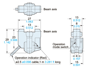
Dimensions
- Unit: mm in
I/O Circuit and Wiring diagrams
I/O circuit diagram
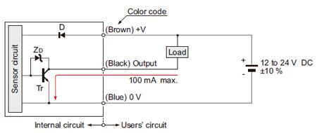
Symbols・・・
D: Reverse supply polarity protection diode
ZD: Surge absorption zener diode
Tr: NPN output transistor
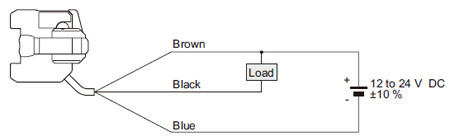
Wiring diagram
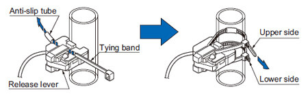
Mounting
- Mount the sensor on a pipe with the attached tying bands and anti-slip tubes as shown in the figure below. Make sure that the release lever is retracted (position as in the figure) before mounting. Fasten two tying bands, as shown, and cut off the excess portions.
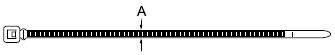
- If other tying bands are to be used, the dimension A shown in the figure below should be 2.5 mm 0.098 in or less.
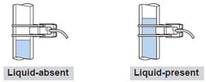
Selecting output operation
- Either Light-ON (Liquid-absent-ON) or Dark-ON (Liquidpresent- ON) can be selected with the operation mode switch according to your application.
- The indicator operation and the output operation are different with the setting of the operation mode switch as given in the table below.
 : Lights up
 : Lights off
| MODE | Sensing condition | Operation indicator | Output operation |
|---|---|---|---|
| Light-ON (Liquid-absent-ON) | Liquid-present |
| OFF |
| Liquid-absent |
| ON | |
| Dark-ON (Liquid-present-ON) | Liquid-present |
| ON |
| Liquid-absent |
| OFF |
Others
- Do not use during the initial transient time (50 ms) after the power supply is switched on.
- Do not use this sensor with a pipe which is not transparent.
- Unclear or highly viscous liquid may not be detected.
- Fit the sensor to the pipe securely, otherwise the operation may be erroneous.
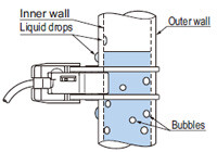
- Take care that no dew condenses on the pipe’s sensing surface or the pipe’s inside wall and that no bubble attaches on the pipe’s inside wall, since it can affect the operation. If a liquid drop flows down across the sensing point or an air bubble sticks on the wall at the sensing point, the operation may be erroneous. Make sure that no bubble arises in the liquid, and that no dew or liquid drop is present on either surface of the pipe wall.
- EX-F1 is not water-proof or chemical-resistant. Installation should be avoided at any place where it could come in direct contact with water or chemicals.