Basic Information
Reliable object detection in limited area


Features
Stable convergent distance sensing
Due to convergent distance sensing, the color or material of the object has almost no effect. Further, the background also has very little effect, enabling stable sensing.
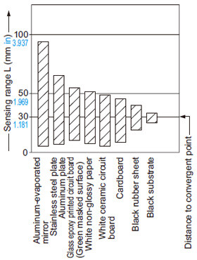
EX-43: Correlation between material and sensing range
Compact size (W10 x H29 x D18 mm W0.394 x H1.142 x D0.709 in)
It can be installed in a limited space.
Various applications
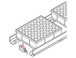
Diffused beam type
Even in a limited sensing area, the sensor is not affected by small perforations or unevenness. It is suitable for presence detection.

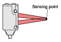
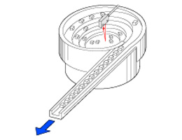
Spot-beam type
- Visible red spot beam allows easy targetting.
- It is suitable for positioning because of its 0.05 mm 0.002 in repeatability.
Applications
Positioning of a PCB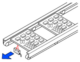
Order guide
| Type | Appearance | Sensing range (Note 1) | Model No. | Output | Sensitivity adjuster | Timer function | Emitting element | |
|---|---|---|---|---|---|---|---|---|
| Diffused beam type |
| 5 to 38 mm 0.197 to 1.496 in (Convergent point: 20 mm 0.787 in) | EX-42 | NPN open- collector transistor | - | - | Infrared LED | |
| Long sensing range | 10 to 70 mm 0.394 to 2.756 in (Convergent point: 40 mm 1.575 in) | EX-44 | Incorporated | |||||
| Spot-beam type | 20 to 35 mm 0.787 to 1.378 in (Convergent point: 30 mm 1.181 in) | EX-43 | Red LED | |||||

Note 1 :
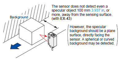
The sensor does not detect even a specular background if it is separated by the distance specified below.
EX-42...150 mm 5.906 in or more, EX-44...300 mm 11.811 in or more, EX-43...100 mm 3.937 in or more
(These are typical values. However, the specular background should be a plane surface, directly facing the sensor. A spherical or curved background may be detected.)
5 m 16.404 ft cable length type
5 m 16.404 ft cable length type (standard: 2 m 6.562 ft) is also available.
When ordering this type, suffix "-C5" to the model No.
(e.g.) 5 m 16.404 ft cable length type of EX-42 is "EX-42-C5".
Option
| Designation | Model No. | Description | |
|---|---|---|---|
| Sensor mounting bracket | MS-EX40-1 | Rear mounting bracket | |
| MS-EX40-2 | Bottom mounting bracket | ||
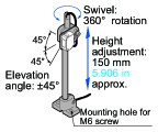
| Universal sensor mounting stand (Note) | MS-AJ1 | Horizontal mounting type | Basic assembly |
| MS-AJ2 | Vertical mounting type | ||
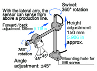
| MS-AJ1-A | Horizontal mounting type | Lateral arm assembly | |
| MS-AJ2-A | Vertical mounting type | ||
Note :Refer to the universal sensor mounting stand MS-AJ for details.
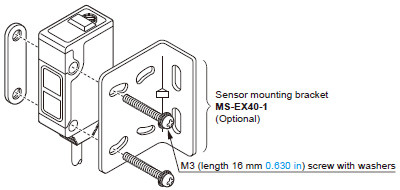
Sensor mounting bracket
MS-EX40-1
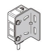
Two M3 (length 16 mm0.630 in) screws with washers are attached.
MS-EX40-2
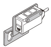
Two M3 (length 16 mm0.630 in) screws with washers are attached.
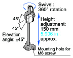
Universal sensor mounting stand
MS-AJ1
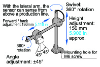
MS-AJ1-A
MS-AJ2
MS-AJ2-A
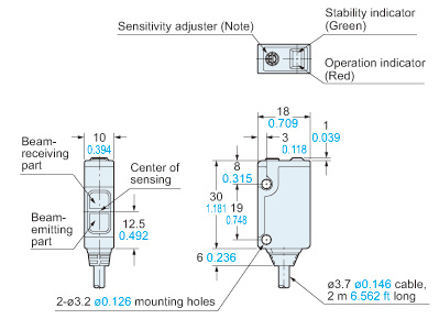
Dimensions
- Unit: mm in
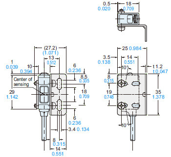
EX-42
Sensor
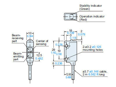
Note :The shape has been changed from the production in June 2021.Click here for the shape of the old product.
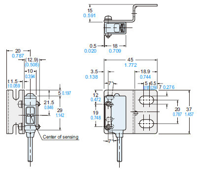
EX-43 EX-44
Sensor
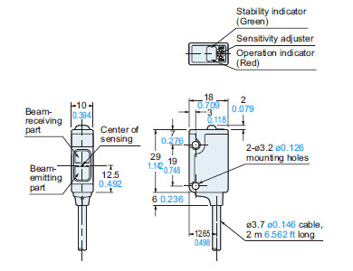
Note :The shape has been changed from the production in June 2021.Click here for the shape of the old product.
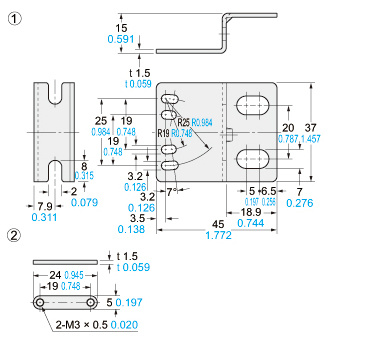
MS-EX40-1
Sensor maunting bracket (Optional)
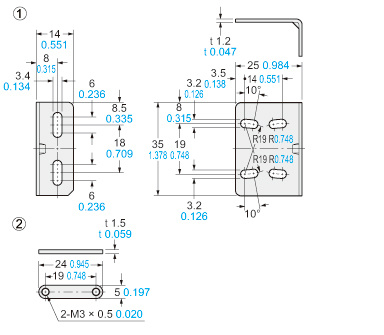
Material:Stainless steel (SUS304)Two M3 (length 16 mm0.630 in) screws with washers are attached.
Assemblg dimensions
MS-EX40-2
Sensor mounting bracket (Optional)
Material:Stainless steel (SUS304)Two M3 (length 16 mm0.630 in) screws with washers are attached.
Assembly dimensions
Old products (For production before May 2021)
EX-42 EX-44 EX-43
EX-43T(Discontinued products)
Sensor
Note:EX-42 does not incorporate it. In EX-43T, it is the timer adjuster.
I/O Circuit and Wiring diagrams
I/O circuit diagram
* I/O circuit diagram has been changed from the production in June 2021.
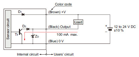
Symbols・・・
D1 : Reverse supply polarity protection diode
D2 : Reverse output polarity protection diode
ZD: Surge absorption zener diode
Tr: NPN output transistor
Old products (For production before May 2021)
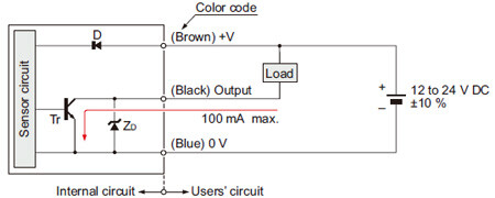
Symbols・・・
D : Reverse supply polarity protection diode
ZD: Surge absorption zener diode
Tr: NPN output transistor
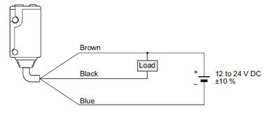
Wiring diagram
Sensing characteristics
EX-42
Sensing field
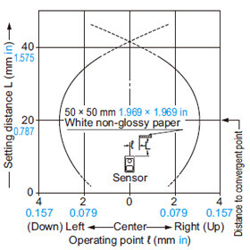
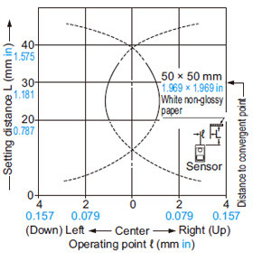
Correlation between sensing object size and sensing range

As the sensing object size becomes smaller than the standard size (white non-glossy paper 50 × 50 mm 1.969 × 1.969 in), the sensing range shortens, as shown in the left graph.
(For plotting the left graph, a sensor having a sensitivity such that it can just detect a 50 × 50 mm 1.969 × 1.969 in white non-glossy paper at a distance of 38 mm 1.496 in has been used.)
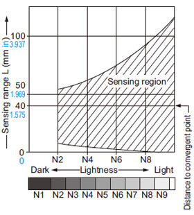
Correlation between lightness and sensing range
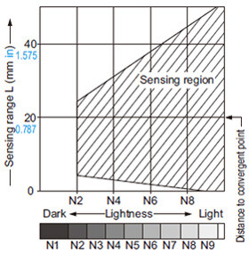
The sensing region (typical) is represented by oblique lines in the left figure. However, the sensitivity should be set with enough margin because of slight variation in products.
(Lightness shown on the left may differ slightly from the actual object condition.)
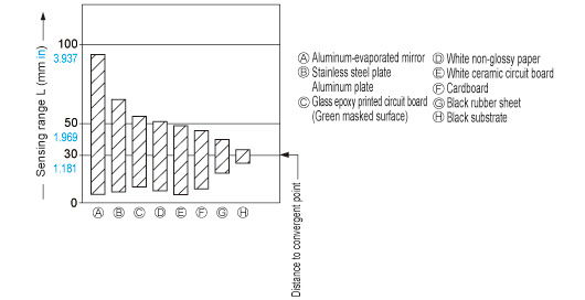
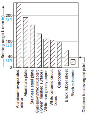
Correlation between material (50 × 50 mm 1.969 × 1.969 in) and sensing range
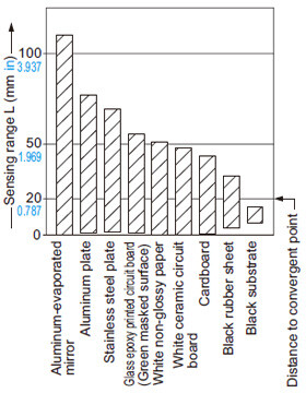
The bars in the graph indicate the sensing range (typical) for the respective material.
However, there is a slight variation in the sensing range depending on the product.
Further, if there is a reflective object (conveyor, etc.) in the background of the sensing object, since it affects the sensing, separate it by more than twice the sensing range shown in the left graph.
EX-44
Sensing field
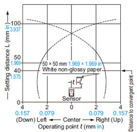
Correlation between sensing object size and sensing range

As the sensing object size becomes smaller than the standard size (white non-glossy paper 50 × 50 mm 1.969 × 1.969 in), the sensing range shortens, as shown in the left graph.
(For plotting the left graph, the sensitivity has been set such that a 50 × 50 mm 1.969 × 1.969 in white non-glossy paper is just detectable at a distance of 70 mm 2.756 in.)
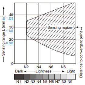
Correlation between lightness and sensing range
The sensing region (typical) is represented by oblique lines in the left figure. However, the sensitivity should be set with enough margin because of slight variation in products.
(The graph is drawn for the maximum sensitivity setting.)
(Lightness shown on the left may differ slightly from the actual object condition.)
Correlation between material (50 × 50 mm 1.969 × 1.969 in) and sensing range
The bars in the graph indicate the sensing range (typical) for the respective material.
However, there is a slight variation in the sensing range depending on the product.
Further, if there is a reflective object (conveyor, etc.) in the background of the sensing object, since it affects the sensing, separate it by more than twice the sensing range shown in the left graph, or adjust the sensitivity adjuster.
(The graph is drawn for the maximum sensitivity setting.)
EX-43
EX-43T (Discontinued products)
Sensing field
Correlation between lightness and sensing range
The sensing region (typical) is represented by oblique lines in the left figure. However, the sensitivity should be set with enough margin because of slight variation in products.
(The graph is drawn for the maximum sensitivity setting. However, EX-43T does not incorporate the sensitivity adjuster.)
(Lightness shown on the left may differ slightly from the actual object condition.)
Correlation between material (50 × 50 mm 1.969 × 1.969 in) and sensing range
The bars in the graph indicate the sensing range (typical) for the respective material.
However, there is a slight variation in the sensing range depending on the product.
Further, if there is a reflective object (conveyor, etc.) in the background of the sensing object, since it affects the sensing, separate it by more than twice the sensing range shown in the left graph, or adjust the sensitivity adjuster.
(The graph is drawn for the maximum sensitivity setting. However, EX-43T does not incorporate the sensitivity adjuster.)
Cautions For Use
- Never use this product as a sensing device for personnel protection.
- In case of using sensing devices for personnel protection, use products which meet laws and standards, such as OSHA, ANSI or IEC etc., for personnel protection applicable in each region or country.
Mounting
- With the optional sensor mounting bracket, the tightening torque should be 0.5 N·m or less.
Others
- Do not use during the initial transient time (50 ms) after the power supply is switched on.
Discontinued products
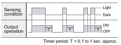
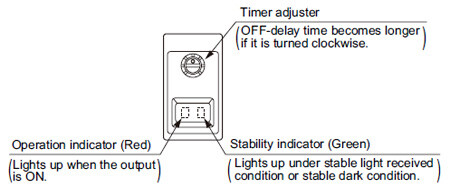
Timer function (Only for EX-43T)
- The variable OFF-delay timer prolongs the output for a certain period (0.1 to 1 sec. approx.).
It is useful when the connected device has a slow response time or when small objects are sensed and the signal width is small.
(The timer is always effective.)
Adjusters
Time chart