Basic Information
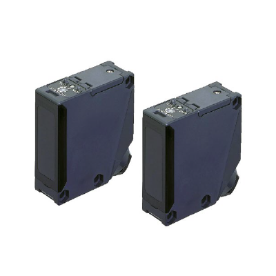
Long range sensing capability to 2.5 m 8.202 ft
Stable sensing unaffected by color or material


CE(Low Voltage Directive) : Multi-voltage type only
UKCA(Low Voltage Regulations) : Multi-voltage type only
UL/C-UL : Recognition (DC-voltage type only)
GB : Multi-voltage type only
Features
Long sensing range
An adjustable range to 2.5 m 8.202 ft allows plenty of space for installation.
1 m 3.281 ft sensing range type also available. Adjust the volume easily to suit your needs when using at close range.
Impervious to variations color or angle
The optical system has been optimized. Since the sensor is hardly influenced at all by angles or the gloss of objects compared to the previous model, it is possible to detect both white objects and black objects at almost a constant distance.
(The difference in sensing range between white non-glossy paper and gray non-glossy paper (lightness: 5) is approx 5% when set at a distance of 2 m 6.562 ft.)
Hardly affected by background objects
Because the sensor doesn’t detect objects outside the preset sensing field by using the 2-segment photodiode adjustable range system, it will not malfunction even if someone walks behind the sensing object or machines or conveyors are in the background.
Note:
Please note that malfunction may occur when there are specular objects or objects with a mirror-like surface in the background.
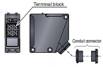
Convenient terminal block type
Cabling enabled by way of a terminal block that eliminates waste.
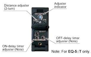
An easy to set adjuster with indicator
Equipped with a 2-turn adjuster with indicator, making it easy to set for short or long distances.
Equipped with both NPN and PNP outputs [EQ-51□]
We've added a DC-voltage type with NPN and PNP transistor outputs all in one sensor. Its BGS / FGS function controls any background effects for more stable sensing.
![Equipped with both NPN and PNP outputs [EQ-51□]](https://ap.industry.panasonic.com/hubfs/pid-corp/products/fasys/sensor/photoelectric/eq-500/images/pic08.jpg)
Multi-voltage [EQ-50□]
Because it can function with 24 to 240 V AC and 12 to 240 V DC, almost any power supply anywhere in the world will do.
Convenient timer function models
Types with an ON-delay / OFF-delay timer available. OFF-delay, e.g. useful when the response of the connected device is slow, ON-delay, e.g. useful to detect objects that take a long time to move.
- Operation: ON-delay, OFF-delay
- Timer period: 0.1 to 5 sec.
(individual setting possible)
BGS / FGS functions make even the most challenging settings possible!
<The BGS function is best suited for background not present>
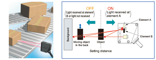
- When object and background are separated
BGS (Background suppression) function
The sensor judges that an object is present when light is received at position A of the light-receiving element (2-segment element).
This is useful if the object and background are far apart.
Not affected if the background color changes or someone passes behind the conveyor.
<The FGS function is best suited for background present>
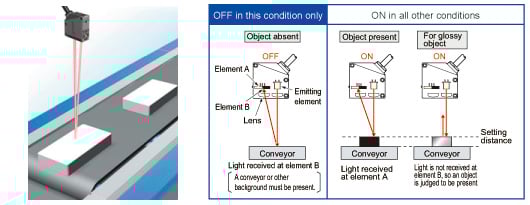
- When object and background are close together
- When the object is glossy or uneven
FGS (Foreground suppression) function
The sensor judges that no object is present when light is received at position B of the light receiving element (2-segment element) (The conveyor is detected). This function is useful if the object and the background are close together or if the object is glossy or uneven.
However, sensing is impossible if there is no background (conveyor, etc.).
Little affected by contamination on lens
Even if the lens surface gets somewhat dirty from dust particles, there is very little change in the operation field, by usage adjustable range system.
Waterproof
The sensors features an IP67 rating to allow their use in process lines where water is used or splashed.
Note: If water splashes on the sensor during sensing operation, it may sense water as an object.

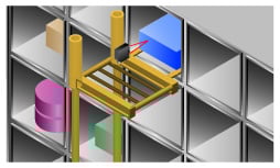
Applications
・Level check within the hopper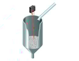
The distance to the object can be set to enable residual amount sensing in the hopper regardless of color.
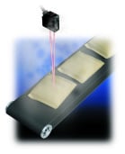
・Confirmation of the passage of packages on a conveyor belt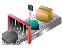
Can accurately detect packages even if they vary in size and color.
Order guide
| Type | Appearance | Sensing range | Model No. | Supply voltage | Output | Timer function | |
|---|---|---|---|---|---|---|---|
| Multi-voltage |
| 0.1 to 2.5 m 0.328 to 8.202 ft | EQ-501 | 24-240 V AC ±10% or 12 to 240 V DC ±10% | Relay contact 1a | - | |
| With timer | EQ-501T | ON-delay / OFF-delay timer (Timer period: 0.1 to 5 sec.) | |||||
| 0.1 to 1.0 m 0.328 to 3.281 ft | EQ-502 | - | |||||
| With timer | EQ-502T | ON-delay / OFF-delay timer (Timer period: 0.1 to 5 sec.) | |||||
| DC-voltage | 0.1 to 2.5 m 0.328 to 8.202 ft | EQ-511 | 12 to 24 V DC ±10% | NPN open-collector transistor PNP open-collector transistor (Equipped with 2 outputs) | - | ||
| With timer | EQ-511T | ON-delay / OFF-delay timer (Timer period: 0.1 to 5 sec.) | |||||
| 0.1 to 1.0 m 0.328 to 3.281 ft | EQ-512 | - | |||||
| With timer | EQ-512T | ON-delay / OFF-delay timer (Timer period: 0.1 to 5 sec.) | |||||

Option
| Designation | Model No. | Description |
|---|---|---|
| Sensor mounting bracket | MS-EQ5-01 | Foot / back angled ounting bracket |
Sensor mounting bracket
MS-EQ5-01
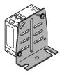
Two M5 (length 30 mm1.181 in) screws with washers and two nuts are attached.
Specifications
| Type | Multi-voltage | ||||
|---|---|---|---|---|---|
| With timer | With timer | ||||
| Model No. | EQ-501 | EQ-501T | EQ-502 | EQ-502T | |
| Regulatory compliance | ・Low Voltage Directive : EN IEC 60947-5-2 ・EMC Directive : EN IEC 60947-5-2 ・RoHS Directive ・GB/T 14048.10 | ||||
| Certification | - | ||||
| Adjustable range (Note 2,3) | 0.2 to 2.5 m 0.656 to 8.202 ft | 0.2 to 1.0 m 0.656 to 3.281 ft | |||
| Sensing range (at max. setting distance) (Note 3) | 0.1 to 2.5 m 0.328 to 8.202 ft | 0.1 to 1.0 m 0.328 to 3.281 ft | |||
| Hysteresis (Note 3) | 10 % or less of operation distance | ||||
| Repeatability (perpendicular to sensing axis) | 10 mm (Note 3) | 4 mm (Note 3) | |||
| Supply voltage | 24-240 V AC ±10 % or 12 to 240 V DC ±10 % Ripple P-P 10 % or less | ||||
| Power / Current consumption | AC: 4 VA or less DC: 3 W or less | AC: 5 VA or less DC: 4 W or less | AC: 4 VA or less DC: 3 W or less | AC: 5 VA or less DC: 4 W or less | |
| Output | Relay contact 1a • Switching capacity: 2 50 V AC 3 A (resistive load), 30 V DC 3 A (resistive load) • Electrical life: 100,000 or more switching operations (switching frequency 1,200 operations/hour) • Mechanical life: 50 million or more switching operations (switching frequency 18,000 operations/hour) | ||||
| Output operation | Switchable either Detection-ON or Detection-OFF | ||||
| Short-circuit protection | - | ||||
| Response time | 20 ms or less (For EQ-50□T depends on the setting timer period) | ||||
| Operation indicator | Orange LED (lights up when the output is ON) | ||||
| Stability indicator | Green LED (lights up under stable operating condition) | ||||
| Distance adjuster | 2-turn mechanical adjuster with indicator | ||||
| Sensing mode | - | ||||
| Timer function | - | Incorporated with variable (0.1 to 5 sec.) ON-delay / OFF-delay timer | - | Incorporated with variable (0.1 to 5 sec.) ON-delay / OFF-delay timer | |
| Automatic interference prevention function | Incorporated (Note 4) | ||||
| Protection | IP67 (IEC) | ||||
| Ambient temperature | –25 to +55 ℃ –13 to +131 ℉ (No dew condensation or icing allowed), Storage: –30 to +70 ℃ –22 to +158 ℉ | ||||
| Ambient humidity | 35 to 85 % RH, Storage: 35 to 85 % RH | ||||
| Ambient illuminance | Incandescent light: 3,000 Lx or less at the light-receiving face | ||||
| Voltage withstandability | 1,500 V AC for one min. between all supply terminals connected together and enclosure, 2,000 V AC for one min. between power supply and output terminals, 1,000 V AC for one min. between relay contact terminals | ||||
| Insulation resistance | 100 MΩ, or more, with 500 V DC megger among supply terminals, non-supply metal parts and relay contact output terminals as well as between relay contacts | ||||
| Vibration resistance | 10 to 55 Hz frequency, 1.5 mm 0.059 in double amplitude in X, Y and Z directions for two hours each | ||||
| Shock resistance | 500 m/s2 acceleration (50 G approx.) in X, Y and Z directions three times each | ||||
| Emitting element | Infrared LED (Peak emission wavelength: 855 nm 0.034 mil, modulated) | ||||
| Receiving element | 2-segment photodiode | ||||
| Material | Enclosure: ABS, Front cover: Polycarbonate, Display cover: Polycarbonate | ||||
| Connection method | Screw-on terminal connection | ||||
| Cable | Suitable for round cable φ9 to φ11 mm φ0.354 to φ0.433 in | ||||
| Cable length | Total length up to 100 m 328.084 ft is possible with 0.3 mm2, or more, cabtyre cable. | ||||
| Weight | Net weight: 100 g approx. | ||||
| Accessory | Adjusting screwdriver: 1 pc. | ||||
Notes:
1)Where measurement conditions have not been specified precisely, the conditions used were an ambient temperature of +23 ℃ +73.4 ℉.
2)The adjustable range stands for the maximum sensing range which can be set with the distance adjuster. The sensor can also detect an object 0.1 m 0.328 ft, or more, away.
3)The adjustable range, sensing range, hysteresis and repeatability are specified for white non-glossy paper (200 x 200 mm 7.874 x 7.874 in) as the object.
4)Note that the detection may be unstable depending on the mounting conditions or the sensing object. In the state that this product is mounted, be sure to check the operation with the actual sensing object.
| Type | DC-voltage | ||||
|---|---|---|---|---|---|
| With timer | With timer | ||||
| Model No. | EQ-511 | EQ-511T | EQ-512 | EQ-512T | |
| Regulatory compliance | ・EMC Directive : EN 60947-5-2 ・RoHS Directive | ||||
| Certification | UL/c-UL certification | ||||
| Adjustable range (Note 2,3) | 0.2 to 2.5 m 0.656 to 8.202 ft | 0.2 to 1.0 m 0.656 to 3.281 ft | |||
| Sensing range (at max. setting distance) (Note 3) | 0.1 to 2.5 m 0.328 to 8.202 ft | 0.1 to 1.0 m 0.328 to 3.281 ft | |||
| Hysteresis (Note 3) | 10 % or less of operation distance | ||||
| Repeatability (perpendicular to sensing axis) | 10 mm (Note 3) | 4 mm (Note 3) | |||
| Supply voltage | 12 to 24 V DC ±10 % Ripple P-P 10 % or less | ||||
| Power / Current consumption | 45 mA or less | ||||
| Output | NPN open-collector transistor • Maximum sink current: 100 mA • Applied voltage: 30 V DC or less (between output and 0 V) • Residual voltage: 1 V or less (at 100 mA sink current), 0.4 V or less (at 16 mA sink current) PNP open-collector transistor • Maximum source current: 100 mA • Applied voltage: 30 V DC or less (between output and +V) • Residual voltage: 1 V or less (at 100 mA source current), 0.4 V or less (at 16 mA source current) | ||||
| Output operation | Switchable either Detection-ON or Detection-OFF | ||||
| Short-circuit protection | Incorporated | ||||
| Response time | 2 ms or less (For EQ-51□T depends on the setting timer period) | ||||
| Operation indicator | Orange LED (lights up when the output is ON) | ||||
| Stability indicator | Green LED (lights up under stable operating condition) | ||||
| Distance adjuster | 2-turn mechanical adjuster with indicator | ||||
| Sensing mode | Switchable either BGS or FGS function | ||||
| Timer function | - | Incorporated with variable (0.1 to 5 sec.) ON-delay / OFF-delay timer | - | Incorporated with variable (0.1 to 5 sec.) ON-delay / OFF-delay timer | |
| Automatic interference prevention function | Incorporated (Note 4) | ||||
| Protection | IP67 (IEC) | ||||
| Ambient temperature | –25 to +55 ℃ –13 to +131 ℉ (No dew condensation or icing allowed), Storage: –30 to +70 ℃ –22 to +158 ℉ | ||||
| Ambient humidity | 35 to 85 % RH, Storage: 35 to 85 % RH | ||||
| Ambient illuminance | Incandescent light: 3,000 Lx or less at the light-receiving face | ||||
| Voltage withstandability | 1,000 V AC for one min. between all supply terminals connected together and enclosure | ||||
| Insulation resistance | 20 MΩ, or more, with 250 V DC megger between all supply terminals connected together and enclosure | ||||
| Vibration resistance | 10 to 55 Hz frequency, 1.5 mm 0.059 in double amplitude in X, Y and Z directions for two hours each | ||||
| Shock resistance | 500 m/s2 acceleration (50 G approx.) in X, Y and Z directions three times each | ||||
| Emitting element | Infrared LED (Peak emission wavelength: 855 nm 0.034 mil, modulated) | ||||
| Receiving element | 2-segment photodiode | ||||
| Material | Enclosure: ABS, Front cover: Polycarbonate, Display cover: Polycarbonate | ||||
| Connection method | Screw-on terminal connection | ||||
| Cable | Suitable for round cable φ9 to φ11 mm φ0.354 to φ0.433 in | ||||
| Cable length | Total length up to 100 m 328.084 ft is possible with 0.3 mm2, or more, cabtyre cable. | ||||
| Weight | Net weight: 85 g approx. | ||||
| Accessory | Adjusting screwdriver: 1 pc. | ||||
Notes:
1)Where measurement conditions have not been specified precisely, the conditions used were an ambient temperature of +23 ℃ +73.4 ℉.
2)The adjustable range stands for the maximum sensing range which can be set with the distance adjuster. The sensor can also detect an object 0.1 m 0.328 ft, or more, away.
3)The adjustable range, sensing range, hysteresis and repeatability are specified for white non-glossy paper (200 x 200 mm 7.874 x 7.874 in) as the object.
4)Note that the detection may be unstable depending on the mounting conditions or the sensing object. In the state that this product is mounted, be sure to check the operation with the actual sensing object.
Low Voltage Directive related information
| Type | Multi-voltage | |||
|---|---|---|---|---|
| With timer | With timer | |||
| Model No. | EQ-501 | EQ-501T | EQ-502 | EQ-502T |
| Utilization category | AC-12/DC-12 | |||
| Impulse withstand voltage | 2.5 kV | |||
| Output minimum operational current | DC 5 V 1 mA or more | |||
| Turn on time / Turn off time (Note 3) | 20 ms / 20 ms | |||
| Maximum response frequency (Note 4) | 25 Hz | |||
| Pollution degree | 3 (Industrial environment) | |||
| Class of protection against electric shock | Out of classification | |||
| Excess gain | 12 % (Note 5) | |||
Note:
1)Where measurement conditions have not been specified precisely, the conditions used were an ambient temperature of +23 ℃ +73.4 ℉.
2)Be sure to add a short-circuit protection (a fuse or a breaker) to the power supply input and the output.
In addition, use 5A or less fast blow fuse or breaker.
3)Turn-On time and Turn-OFF time are the delay time between reference sensor and measurement sensor in case round plate rotates as below.
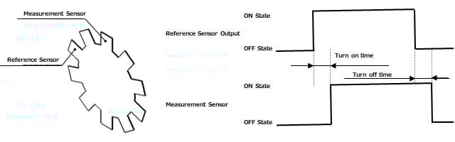
4)The maximum response frequency is the value calculated below.
Maximum response frequency = 1 / (Turn on time+Turn off time)
5)Excess gain is the value in case the distance setting adjuster is positined in maximum state.
In addition, sensing object 200mm x 200mm is the value in case of non-glossy white paper.
Dimensions
- Unit: mm in
EQ-501(T) EQ-502(T) EQ-511(T) EQ-512(T)
Sensor
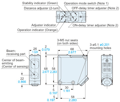
Notes:1) The operation mode switch of the DC-voltage type is the DIP switch.2) For EQ-5□T only.
Assembly dimensions with sensor mounting bracket
MS-EQ5-01 (Optional) (Foot angled mounting)
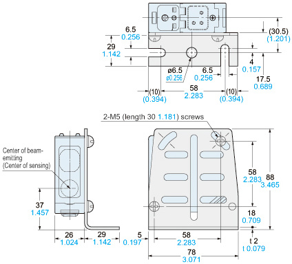
Material:Cold rolled carbon steel (SPCC)Two M5 (length 30 mm1.181 in) screws with washers and two nuts are attached
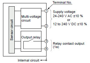
I/O Circuit and Wiring diagrams
EQ-501(T) EQ-502(T)
I/O circuit diagram
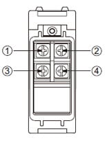
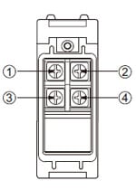
Terminal arrangement diagram
EQ-511(T) EQ-512(T)
I/O circuit diagram
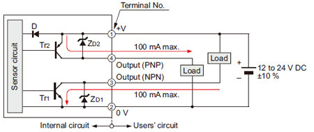
Symbols・・・
D: Reverse supply polarity protection diode
ZD1, ZD2: Surge absorption zener diode
Tr1: NPN output transistor
Tr2: PNP output transistor
Terminal arrangement diagram
Sensing characteristics
EQ-501(T) EQ-511(T)
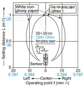
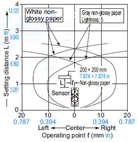
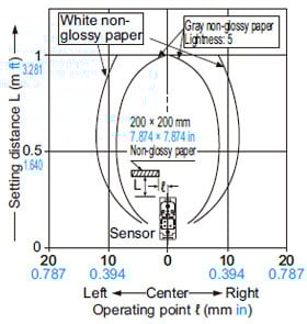
Sensing fields
• Setting distance: 1 m 3.281 ft
• Setting distance: 2.5 m 8.202 ft
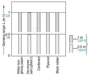
Correlation between material
(200 × 200 mm 7.874 × 7.874 in) and sensing range

These bars indicate the sensing range with the respective objects when the distance adjuster is set to a sensing range of 2.5 m 8.202 ft / 1 m 3.281 ft long, respectively, with white non-glossy paper.
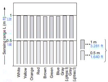
Correlation between color
(200 × 200 mm 7.874 × 7.874 in non-glossy paper) and sensing range
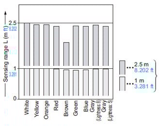
These bars indicate the sensing range with the respective colors when the distance adjuster is set to a sensing range of 2.5 m 8.202 ft / 1 m 3.281 ft long, respectively, with white non-glossy paper.
The sensing range also varies depending on material.
Emitted beam
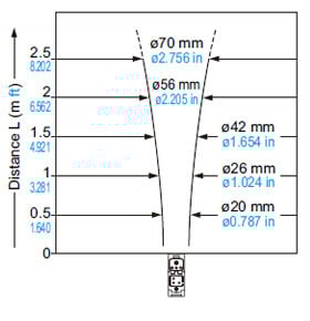
Correlation between sensing object size and sensing range

This curve shows the characteristics with the maximum sensing range set to 2.5 m 8.202 ft, with white non-glossy paper (200 × 200 mm 7.874 × 7.874 in).
EQ-502 (T) EQ-512 (T)
Sensing fields
• Setting distance: 0.5 m 1.640 ft

• Setting distance: 1 m 3.281 ft
Correlation between material
(200 × 200 mm 7.874 × 7.874 in) and sensing range
These bars indicate the sensing range with the respective objects when the distance adjuster is set to a sensing range of 1 m 3.281 ft / 0.5 m 1.640 ft long, respectively, with white non-glossy paper.
Correlation between color (200 × 200 mm 7.874 × 7.874 in non-glossy paper) and sensing range
These bars indicate the sensing range with the respective colors when the distance adjuster is set to a sensing range of 1 m 3.281 ft / 0.5 m 1.640 ft long, respectively, with white non-glossy paper.
The sensing range also varies depending on material.
Emitted beam
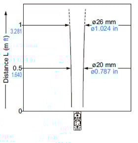
Correlation between sensing object size and sensing range
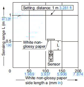
This curve shows the characteristics with the maximum sensing range set to 1 m 3.281 ft, with white non-glossy paper (200 × 200 mm 7.874 × 7.874 in).
Mounting
The tightening torque should be 0.8 N·m or less.
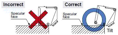
Care must be taken regarding the sensor mounting direction with respect to the object’s direction of movement.

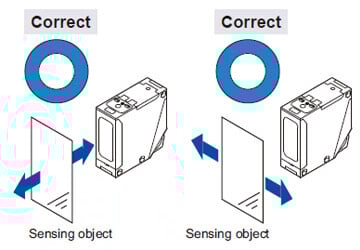
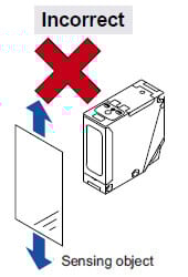
Do not make the sensor detect an object in this direction because it may cause unstable operation.
- When detecting a specular object (aluminum or copper foil, etc.) or an object having a glossy surface or coating, please note that there are cases when the object may not be detected due to a change in angle, wrinkles on the object surface, etc.
- If a specular body is present in the background, faulty operation may be caused due to a small change in the angle of the background body. In that case, install the sensor at an inclination and confirm the operation with the actual sensing object.
- When a specular body is present below the sensor, use the sensor by tilting it slightly upwards to avoid faulty operation.
- This product is not easily affected by the reflected light intensity since this sensor is the adjustable range reflective type. When the reflected light intensity is remarkably low, the sensing range may be affected. In that case, mount the sensor, while checking light-up of the stable indicator (green).
- The mounting screws of the terminal cover and VR cover should certainly be tightened to maintain water-resistance; the tightening torque of the screws should be 0.3 to 0.5 N·m.
Automatic interference prevention function
- When the sensors are mounted closely, use them in the interference prevented area, as shown below.
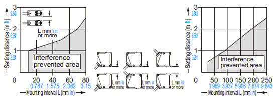
- Note that the detection may be unstable depending on the mounting conditions or the sensing object to be used.
In the state that this product is mounted, be sure to check the operation with the actual sensing object to be used.
Wiring
- Check all wiring before applying power since incorrect wiring may damage the internal circuit. Also, carefully tighten the terminal screws so that the wires of adjacent terminals do not touch.
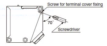
- The mounting hole for the terminal cover fixing screws inclines 70 degrees to the terminal cover, as shown in the figure below.
To avoid damaging this product or screw, take care when tightening or loosening a screw.
- To maintain water-resistance, the cable should have an outer diameter between ø9 to ø11 mm ø0.354 to ø0.433 in with a smooth covering material that allows the attached conduit connector to be securely tightened; the tightening torque of the screw should be of 1.5 to 2.0 N·m.
- If an external surge voltage exceeding 4 kV is impressed (DC-voltage type: 1 kV), the internal circuit will be damaged, and a surge suppressing element should be used.
- Prepare the cable end as shown below.
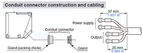
Note:
When assembling the conduit connector, pay attention to the direction of the gland packing.
Furthermore, in order to maintain water-resistance, fit the gland packing such that the seating surface of the gland packing contacts the packing holder part of the terminal cover evenly.
- The size of conduit is M20 × 1.5 mm 0.787 in.
- If pressure terminals are to be used, affix the connected pressure terminals to a terminal (M3.5 screw).
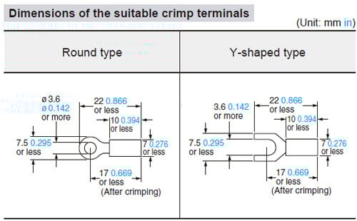
Note:
Use crimp terminals with insulating sleeves.
Recommended crimp terminal: Nominal size 1.25 × 3.5 0.049 × 0.138.
- The tightening torque for the terminal screws should be 0.3 to 0.5 N·m.
Part description
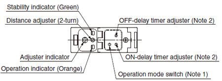
Notes:
1)The operation mode switch of the DC-voltage type is the DIP switch.
Refer to ‘DC-voltage type’ of ‘Operation mode switch’ for details.
2)Incorporated on EQ-5□T only.
Operation mode switch
Multi-voltage type (L-ON / D-ON mode only)
| Operation mode switch | Description |
|---|---|
 | Detection-ON mode is obtained when the switch is turned fully clockwise (L side). |
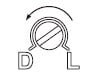 | Detection-OFF mode is obtained when the switch is turned fully counterclockwise (D side). |
Note:
Turn the operation mode switch gradually and lightly with the attached screwdriver. Turning with excessive strength will cause damage to the adjuster.
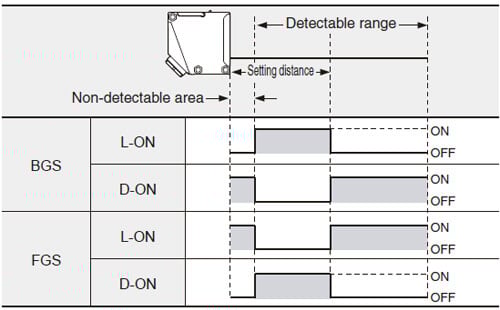
DC-voltage type

BGS / FGS function (DC-voltage type only)
- DC-voltage type sensor incorporates BGS / FGS function.
Select either the BGS or FGS function depending on the positions of the background and sensing object. - BGS / FGS function is set with the operation mode switch.
- FGS function is used when the sensing object contacts the background (conveyor, etc).
- Depends on a selection of either BGS or FGS function, the output operation changes as follows.
Timer function (EQ-5□T only)
- EQ-5□ incorporates an OFF-delay timer, which is useful when the response of the connected device is slow, etc., and an ON-delay timer, which is useful for detecting objects that move slowly, for example.
- The OFF-delay and ON-delay timers can be used simultaneously.
- For DC-voltage type, set the DIP switch for the timer mode to ‘Timer ON’ side.

Timer period: T = 0.1 to 5 sec. (variable)
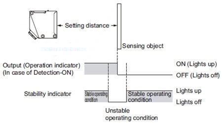
Stability indicator
- Since the EQ-500 series uses a 2-segment photodiode as its receiving element, and sensing is done based on the difference in the incident beam angle of the reflected beam from the sensing object, the output and the operation indicator (orange) operate according to the object distance.
Furthermore, the stability indicator (green) shows the margin of the setting distance.
Others
- This product has been developed / produced for industrial use only.
- This product is suitable for indoor use only.
- Do not use during the initial transient time (50 ms) after the power supply is switched on.
- Its distance adjuster is mechanically operated. Do not drop; avoid other shocks.