Discontinued Products
Specifications
| Type | Small and built-in connector type | ||||||
|---|---|---|---|---|---|---|---|
| K type | T type | L type | Y type | F type | R type | ||
| Model No. | NPN output | PM-K64 | PM-T64(W) | PM-L64 | PM-Y64 | PM-F64 | PM-R64 |
| PNP output | PM-K64P | PM-T64P | PM-L64P | PM-Y64P | PM-F64P | PM-R64P | |
| Sensing range | 5 mm 0.197 in (fixed) | ||||||
| Minimum sensing object | 0.8 x 1.8 mm 0.031 x 0.071 in opaque object | ||||||
| Hysteresis | 0.05 mm 0.002 in or less (Note 2) | ||||||
| Repeatability | 0.01 mm 0.0004 in or less (Note 3) | ||||||
| Supply voltage | 5 to 24 V DC ±10 % Ripple P-P 10 % or less | ||||||
| Current consumption | 15 mA or less | ||||||
| Output | <NPN output type> NPN open-collector transistor • Maximum sink current: 50 mA • Applied voltage: 30 V DC or less (between output and 0 V) • Residual voltage: 0.7 V or less (at 50 mA sink current), 0.4 V or less (at 16 mA sink current) <PNP output type> PNP open-collector transistor • Maximum source current: 50 mA • Applied voltage: 30 V DC or less (between output and +V) • Residual voltage: 0.7 V or less (at 50 mA source current), 0.4 V or less (at 16 mA source current) | ||||||
| Utilization category | DC-12 or DC-13 | ||||||
| Output operation | Incorporated with 2 outputs: Light-ON / Dark-ON | ||||||
| Response time | Under light received condition: 20 μs or less Under light interrupted condition: 100 μs or less (Response frequency: 1 kHz or more) (Note 4) | ||||||
| Operation indicator | Orange LED (lights up under light received condition) | ||||||
| Pollution degree | 3 (Industrial environment) | ||||||
| Ambient temperature | –25 to +55 ℃ –13 to +131 ℉ (No dew condensation or icing allowed), Storage: –30 to +80 ℃ –22 to +176 ℉ | ||||||
| Ambient humidity | 35 to 85 % RH, Storage: 5 to 95 % RH (Note 5) | ||||||
| Ambient illuminance | Fluorescent light: 1,000 ℓx at the light-receiving face | ||||||
| EMC | EN 60947-5-2 | ||||||
| Voltage withstandability | 1,000 V AC for one min. between all supply terminals connected together and enclosure | ||||||
| Insulation resistance | 50 MΩ, or more, with 250 V DC megger between all supply terminals connected together and enclosure | ||||||
| Vibration resistance | 10 to 2,000 Hz frequency, 1.5 mm 0.059 in amplitude in X, Y and Z directions for two hours each | ||||||
| Shock resistance | 15,000 m/s2 acceleration (1,500 G approx.) in X, Y and Z directions for three times each | ||||||
| Emitting element | Infrared LED (Peak emission wavelength: 940 nm 0.037 mil, non-modulated) | ||||||
| Material | Enclosure: PBT, Slit cover: Polycarbonate | ||||||
| Cable length | Total length up to 100 m 328.084 ft is possible with 0.3 mm2, or more, cable. (Note 6) | ||||||
| Weight | Net weight: 3 g approx. | ||||||
Notes:
1) Where measurement conditions have not been specified precisely, the conditions used were an ambient temperature of +23 ℃ +73.4 ℉.
2) This is the value when a sensing object is moved in a lateral direction to the U-shape.
3) This is the value when a sensing object is moved in a lateral direction to the U-shape and when the inserting length of the sensing board is 5 mm 0.197 in.
4) The response frequency is the value when the disc, given in the figure below, is rotated.

5) 5-35% RH in an ambient temperature of +23 ℃+73.4℉.6) Confirm that the sensor terminal voltage is more than 4.5 V when using an extension of over 20 m65.617 ft.
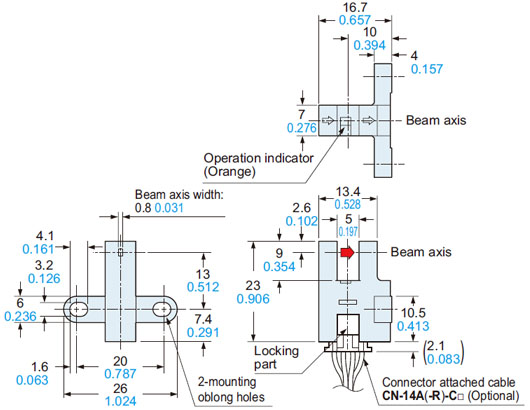
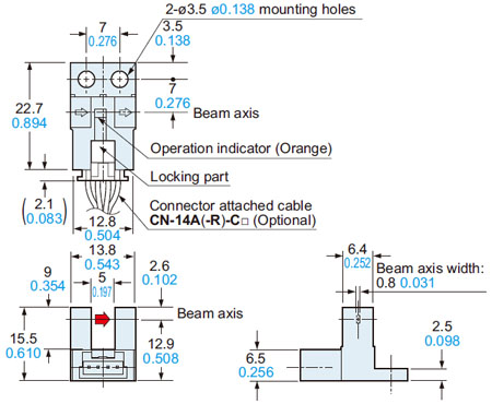
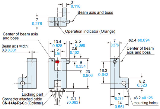
Dimensions
- Unit: mm in
PM-K64(P)
Sensor

PM-T64(P)
Sensor

PM-T64W
Sensor
PM-L64(P)
Sensor

PM-Y64(P)
Sensor
PM-F64(P)
Sensor
PM-R64(P)
Sensor

CN-14A-C□
CN-14A-R-C□
Connector attached cable (Optional)

• Length L
| Model No. | Length L |
|---|---|
| CN-14A(-R)-C1 | 1,000 39.370 |
| CN-14A(-R)-C2 | 2,000 78.740 |
| CN-14A(-R)-C3 | 3,000 118.110 |
| CN-14A(-R)-C5 | 5,000 196.850 |
I/O Circuit and Wiring diagrams
PM-□64(W)
NPN output type
I/O circuit diagram
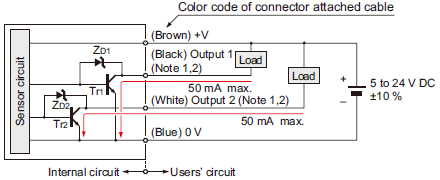
Note:1)Make sure to connect terminals correctly as the sensor does not incorporate a reverse polarity protection circuit.Further, the output is not incorporated with a short-circuit protection circuit. Do not connect it directly to a power supply or a capacitive load. Faulty wiring may result in damage.2)Ensure to insulate the unused output wire.

Terminal arrangement diagram
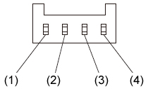
Terminal No.Designation(1)+V(2)Output1: Light-ON(3)Output2: Dark-ON(4)0 V
PM-□64P
PNP output type
I/O circuit diagram
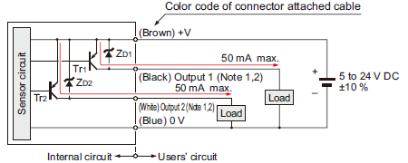
Note:1)Make sure to connect terminals correctly as the sensor does not incorporate a reverse polarity protection circuit.Further, the output is not incorporated with a short-circuit protection circuit. Do not connect it directly to a power supply or a capacitive load. Faulty wiring may result in damage.2)Ensure to insulate the unused output wire.

Terminal arrangement diagram

Terminal No.Designation(1)+V(2)Output1: Light-ON(3)Output2: Dark-ON(4)0 V
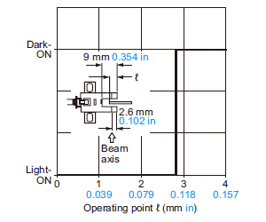
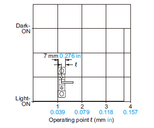
Sensing characteristics
(TYPICAL)
PM-K64(P)
PM-L64(P)
Sensing position
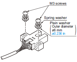
Mounting
- When fixing the sensor with screws, use M3 screws and the tightening torque should be 0.5 N·m or less.
Further, use small, round type plain washers (ø6 mm ø0.236 in).
Wiring
Connection method
<Connector>
Housing: PAP-04V-S
(Manufactured by J.S.T.
Mfg. Co., Ltd.)
- Insert the connector attached cable CN-14A(-R)-C□ in the connector part of this product as shown in the left figure.

| Connector pin No. | Terminal designation |
|---|---|
| (1) | +V |
| (2) | Output 1 |
| (3) | Output 2 |
| (4) | 0 V |
<Connector pin position>
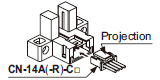
Disconnection method
Note:
Take care that if the cable is pulled out without pressing the projection, the cable may break.
- Pressing the projection of the connector attached cable, pull out the connector.
Cable extension
- Cable extension is possible up to an overall length of 100 m 328.084 ft with a 0.3 mm2, or more, cable.
However, since a voltage drop shall occur due to the cable extension, ensure that the power supply voltage at the end of the cable attached to the sensor or at the sensor terminals is within the rating.
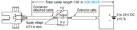
But, when the overall cable length, including the cable attached to the sensor, is as given below, there is no need to confirm the voltage.
| Conductor crosssection area of extension cable | Total cable length |
|---|---|
| 0.08 to 0.1 mm2 | Up to 5 m 16.404 ft |
| 0.2 mm2 | Up to 10 m 32.808 ft |
| 0.3 mm2 | Up to 20 m 65.617 ft |
Others
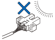
- Since the sensor is intended for use inside machines, no special countermeasures have been taken against extraneous light.
Take care that extraneous light is not directly incident on the beam receiving section.
- Do not use during the initial transient time (50 ms) after the power supply is switched on.
- If the sensor is used in a place having excessive dust, periodically clean the emitting and receiving sections with a dry, soft cloth.
- If there is a large surge generating equipment, such as, motor, solenoid, electromagnetic valve, etc., in the vicinity of the sensor, use a surge absorber on that equipment.
Further, do not run the sensor cables along power lines and use a capacitor between +V and 0 V, if required.
Use the sensor after confirming that the surge has been eliminated.