Basic Information
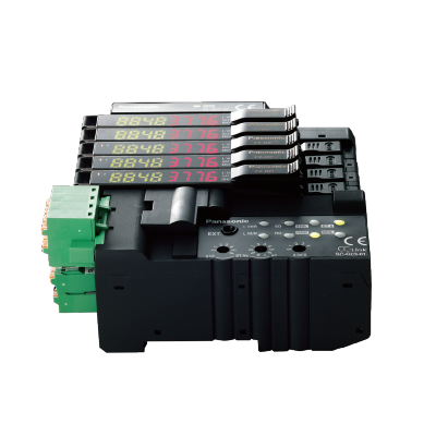
Link digital sensors directly to open networks


SC-GU3-03 has been upgraded in May 2020.
For details, please refer to "Cautions for Use".
>>SC-GU3-03 version identification
SC-GU3 series have become compatible with LS-500 Laser Sensor.
*SC-GU3-01 was changed from shipping in February 2014.
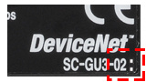
*SC-GU3-02 was changed from shipping in May 2014.
*SC-GU3-03 was changed from shipping in August 2014.
Profile for SC-GU3-01
Features
To minimize life cycle cost
The continuously shortened life cycle of equipment has highlighted the importance of reduced costs during manufacturing and initial installation. Panasonic Industry offers a line of devices, the SC-GU3 series communication units for open network, that maximize the capabilities of open networks, streamline regular maintenance and preventive maintenance, and reduce wiring and installation work. We offer solutions that minimize costs during the life cycle of equipment.

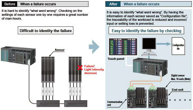
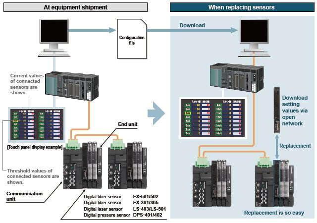
Traceability
It is useful to keep track of the sensor configurations at equipment start-up so that failures can be quickly identified and the user alerted.
(Note) : Maximum of 12 units in case of including the FX-500 / LS-500 series.
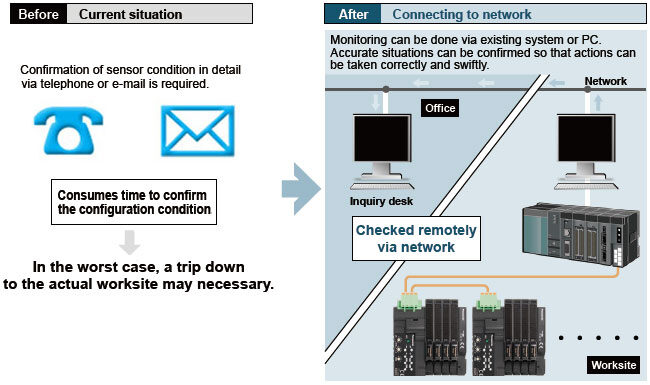
Remote monitoring of equipment
Since the sensor settings can be checked over the network, it is possible to minimize the man-hours spent by field workers to resolve failures of equipment or line.

Streamline maintenance work
By saving the default settings as "Configuration file" when equipment was shipped out, sensor replacement can be smoothly performed by downloading via an open network. Replacement work is also easy, for sensor is equipped with connector that require no tools.
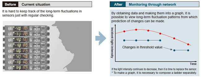
Predictive maintenance
Observe digital data such as incident light intensity or pressure value of sensors and graph them for Predictive maintenance.
Example : Decrease in incident light intensity due to dirt on fiber sensor.
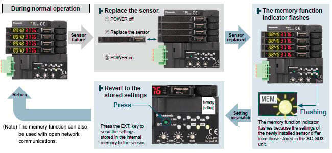
Easy maintenance with the memory function
Store Settings of the connected digital sensors into the SC-GU3 series. Just press the “Setting extension (EXT.)” key and setting data can be transmitted and restored to original status. Maintenance such as sensor replacement can be performed smoothly. Also, the settings stored in the SC-GU3 series is checked against the settings of the digital sensors when the power is turned on. When the setting is different, memory function indicator (MEM.) will flash, and warning signal sent, preventing the equipment from operating with settings changed.

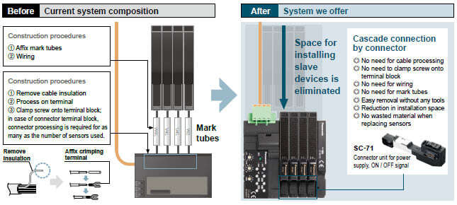
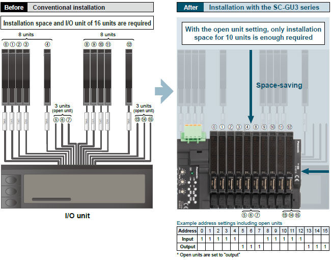
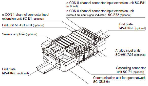
Reduction in wiring, construction, and space
Installation space for slave devices is eliminated. Cascade connection is simply done with connectors so that the time taken for wiring and construction can be reduced.
Space saving with open unit setting
Open unit (sensor) setting is achieved when performing the process for every 1 byte (sensor input for 8 units) in order to make the data control clear, or planning to add sensors later. In addition, the SC-GU3 series minimizes installation space by reducing space required for all I/O units.
Example: In case of dividing 16 units into every 8 units and create open unit for 3 units each.
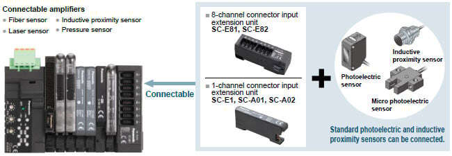
Make use of spare channels
Standard, general-purpose sensors can also be connected in cascade to the SC-GU3 series with connector input units of SC-A01, SC-A02, SC-E1, SC-E81 and SC-E82. Further wire-saving can be achieved.
(Note) Analog output type devices can be connected to the SC-A01 and SC-A02 (1 to 5 V / 4 to 20 mA)
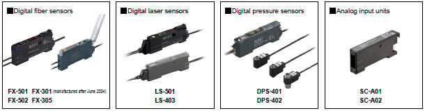
Models that can be connected to the SC-GU3-0□
(Use in combination with cascading connector unit SC-71, with the exception of certain models)
Sensors capable of communicating internal digital values (Models that support optical communications)
Sensors capable of communicating output information (ON / OFF) only (No optical communications)
(Use in combination with cascading connector unit SC-71, with the exception of certain models)
| Fiber sensors | FX-551, FX-301 (B/G/H) |
| Fiber sensors for manual setting | FX-411, FX-412, FX-311 (B/G) |
| Fiber sensors for leak / liquid fiber | FX-301-F, FX-301-F7 |
| Laser sensors | LS-401 |
| Compact inductive proximity sensors | GA-311 |
| 1-channel connector input extension unit | SC-E1, SC-T1J |
| 8-channel connector input extension unit | SC-E81 |
| 8-channel connector input extension unit (without an input signal indicator) | SC-E82 |
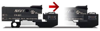
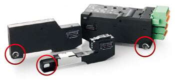
Sensors can be replaced easily without detaching neighboring sensor amplifiers
Sensors are detachable simply by pushing down the lever of cascading connector unit and sliding the sensor amplifier sideways. This improves maintenance.

No tools needed
Sensor amplifier is equipped with one-touch connector, eliminating the need for tools.
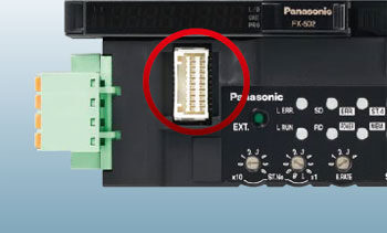
Optical communications for simple installation
the need for tools. Optical communications are used to send and receive data from the end units instead of a link cable. This facilitates easy installation and maintenance.
Parallel output connector
A parallel output connector allows the output signal from each sensor amplifier to be captured in real time.
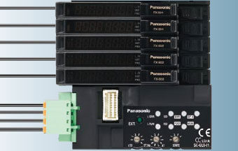
Cable orientation on the left side
All cable connections have been placed on the left side of the communication unit in order to make the most effective use of installation space.

Support for Mitsubishi Electric Corporation’s iQ Sensor Solution SC-GU3-01
The SC-GU3-01 Communication Unit for CC-Link is compatible with Mitsubishi Electric Corporation’s iQ Sensor Solution (iQSS) and can be used in combination with products that support iQSS, for example Mitsubishi Electric Corporation’s MELSEC series.

Mitsubishi Electric Corporation’s iQ Works utility can be used to control digital sensors connected to the SC-GU3-01.
The following functionality is supported by using iQ Works to load CSP+ data.
(Note) CSP+: CC-Link family system profile
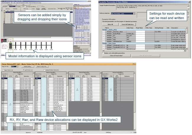
(1)CC-Link configuration information can be used to easily check the configuration of devices connected to the SC-GU3-01. (sensor types [fiber, pressure etc.], cascading configuration, number of units)
(2)A list of sensor-specific parameter data (write / read) can be acquired and changed.
(3)SC-GU3-01 device allocations can be displayed by loading CSP+ data.
(Note)This approach dramatically reduces the need to consult the SC-GU3-01 specifications and manual.
(Note)Capabilities include easy setup, sensor monitor, parameter read / write, and backup / restore.
Requires Mitsubishi Electric Corporation’s GX Works 2 sequencer engineering software Ver. 1.492 or later.
Order guide
| Designation | Appearance | Model No. | Description |
|---|---|---|---|
| Communication unit for CC-Link IE Field |
| SC-GU3-04 | This is a communication unit, which can convert the output signal of a sensor amplifier (NPN output type) into communication data for CC-Link IE Field. |
| Communication unit for CC-Link |
| SC-GU3-01 | This is a communication unit, which can convert the output signal of a sensor amplifier (NPN output type) into communication data for CC-Link. |
| Communication unit for EtherCAT |
| SC-GU3-03 | This is a communication unit, which can convert the output signal of a sensor amplifier (NPN output type) into communication data for EtherCAT. |
| End unit |
| SC-GU3-EU | This end unit can change and check the settings of sensor amplifiers (NPN output type) that allow optical communication and monitor operation status. |
| Cascading connector unit |
| SC-71 | This one-touch connector is used to connect the following devices to SC-GU3-0□: The FX-500/550/410/300(B/G/H)/311 fiber sensor, the LS-500/400 laser sensor, the DPS-400 digital pressure sensor, SC-E1, SC-A01 and SC-A02, etc |
| e-CON 1-channel connector input extension unit |
| SC-E1 | This is a 1-channel connector input extension unit, compatible with an e-CON connector, can be connected to a NPN output type device.(Note 1) Includes power and input signal indicators (for one channel). When using in combination with the SC-GU3 series, use with the SC-71. |
| e-CON 8-channel connector input extension unit |
| SC-E81 | This extension unit can be connected to eight NPN output type devices. Includes power and input signal indicators (for eight channels). |
| e-CON 8-channel connector input extension unit (without an input signal indicator) |
| SC-E82 | This is an 8-channel connector input extension unit, compatible with an e-CON connector, can be connected to eight NPN output type devices.(Note 1) (Uses eight channels of signaling, regardless of the number of connected input devices.) Includes a power indicator. Does not include an input signal indicator. |
| Analog voltage input unit |
| SC-A01 | This extension unit can be connected to NPN output type devices or analog voltage output type devices. When using in combination with the SC-GU3 series, use with the SC-71. |
| Analog current input unit |
| SC-A02 | This extension unit can be connected to NPN output type devices or analog current output type devices. When using in combination with the SC-GU3 series, use with the SC-71. |


Note 1:
Conditions of connectable DC 2-wire type input device
• Leak current: 1 mA or less (when the power is OFF), Offset voltage: 3 V or less (when the power is ON)
• Product whose load current range includes 5 to 8 mA
SYSTEM COMPOSITION
If optical communication is to be used in a system that includes models not compatible with optical communication, connect the incompatible models after the SC-GU3-EU.
A maximum of 12 units can be connected to the FX-500 / LS-500 series, and a maximum of 16 units can be connected to the other sensor amplifiers.
Option
| Designation | Appearance | Model No. | Description |
|---|---|---|---|
| Cable with connector on one end |
| CN-M20-C2 | This cable has a connector for linking to the parallel output signal. |

Discontinued products [Order accepted till September, 2024]

Specifications
- Communication unit for CC-Link IE Field
- Communication unit for CC-Link
- Communication unit for DeviceNet (Discontinued products)
- Communication unit for EtherCAT
- End unit
- e-CON 1-channel connector input extension unit
- e-CON 8-channel connector input extension unit
- e-CON 8-channel connect
- or input extension unit (without an input signal indicator)
- Cascading connector unit
- Analog voltage input unit / Analog current input unit
Communication unit for CC-Link IE Field
| Model No. | SC-GU3-04 | ||||
|---|---|---|---|---|---|
| Applicable regulations and certifications | CE Marking (EMC Directive (Note 1), RoHS Directive), UKCA Marking (EMC Regulations (Note 1), RoHS Regulations) | ||||
| Compatible sensor units | Sensor amplifiers (NPN output type) that can connect to the SC‑71 cascading connector unit (optional) | ||||
| Number of units connectable | Maximum of 16 units can be connected to one SC-GU3-04 unit (Max. 12 units when FX500 / LS-500 series is connected) | ||||
| Supply voltage | 24 V DC +10-15 % Ripple P-P 10 % or less | ||||
| Current consumption | 200 mA or less | ||||
| Allowable passing current | 2A or less (Note 2) | ||||
| Communication method | CC-Link IE Field | ||||
| Remote station type | Remote device station | ||||
| Network No. setting | 1 to 239 (decimal) [1 to EF (hex)] (0 and 240 or higher result in an error) (Note 3) | ||||
| Station No. setting | 1 to 120 (decimal) (0 and 121 or higher result in an error) | ||||
| Cyclic transmission (Maximum number of links per station) | RX / RY:128 points each (128 bits), 16 bytes, RWr / RWw: 64 points each (64 words), 128 bytes | ||||
| Transient transmission | Server function only, data size 1,024 bytes | ||||
| Communication speed | 1 Gbps | ||||
| Transmission line types | Line, star (mixing of line and star types is possible), ring | ||||
| Maximum overall cable distance | 100 m 328.084 ft | ||||
| Maximum number of units connectable | 121 units (1 master station, 120 slave stations) | ||||
| Cascade connection levels | Maximum 20 | ||||
| Ambient temperature | -10 to +50 ℃ +14 to +122 ℉ (8 to 16 units connected: -10 to +45 ℃ +14 to +113 ℉) (No dew condensation or icing allowed) Storage: -20 to +70 ℃ -4 to +158 ℉ | ||||
| Ambient humidity | 35 to 85 % RH, Storage: 35 to 85 % RH | ||||
| Communication cable | Ethernet cable that satisfies 1000BASE-T standard Category 5e or higher (Double-shielded / STP, straight cable) (Note 4) | ||||
| Grounding method | RJ45 connector shield: C connection, Case: floating | ||||
| Material | Enclosure: Polycarbonate | ||||
| Weight | Net weight: 100 g approx., Gross weight: 150 g | ||||
Notes:
1) Ground the shield wire of the Ethernet cable at a higher-level device in order to comply with the EMC Directive on CE Marking and the EMC Regulations on UKCA Marking. This product is not provided with a grounding terminal.
For details, refer to the CC-Link IE Field Network Cable Installation Manual published by the CC-Link Partner Association.
2) Take care that the total consumption current of connected sensor amplifiers and other devices does not exceed the allowable passing current.
3) For the network number setting on this product, convert the network number to hex and set the hex value.
4) Use CC-Link Partner Association recommended cable.
Communication unit for CC-Link SC-GU3-01
| Item | SC-GU3-01 | ||||
|---|---|---|---|---|---|
| Applicable regulations and certifications | CE Marking (EMC Directive, RoHS Directive), UKCA Marking (EMC Regulations, RoHS Regulations) | ||||
| Compatible sensor units | Sensor amplifiers (NPN output type) that can connect to the SC‑71 cascading connector unit (optional) | ||||
| Number of units connectable | Maximum of 16 units can be connected to one SC-GU3-01 unit (Max. 12 units when FX-500 / LS-500 series is connected) | ||||
| Supply voltage | 24 V DC +10-15% Ripple P-P 10 % or less | ||||
| Current consumption | 120 mA or less (excluding connected sensor amplifiers) | ||||
| Allowable passing current | Wire-saving connector 2 A (Note 1), supply connector 6 A (Note 2) | ||||
| Communication method | CC-Link Ver.1.10 | ||||
| Number of occupied station | Switchable 1 or 4 station | ||||
| Communication speed | 10 Mbps | 5 Mbps | 2.5 Mbps | 625 kbps | 156 kbps |
| Total extension length | 100 m 328.084 ft | 150 m 492.126 ft | 200 m 656.168 ft | 600 m 1968.504 ft | 1,200 m 3937.008 ft |
| Communication cable | Specified cable (twist pair cable with shield) (Note 3) | ||||
| Station No. setting | 1 to 64 (0 and 65 or higher result in an error) | ||||
| Remote station type | Remote device station | ||||
| Ambient temperature | –10 to +55 ℃ +14 to +131 ℉ (No dew condensation or icing allowed), (If 4 to 7 units are connected in cascade: –10 to +50 ℃ +14 to +122 ℉, if 8 to 16 units are connected in cascade: –10 to +45 ℃ +14 to +113 ℉) Storage: –20 to +70 ℃ –4 to +158 ℉ | ||||
| Ambient humidity | 35 to 85 % RH, Storage: 35 to 85 % RH | ||||
| Material | Enclosure: Polycarbonate | ||||
| Weight | Net weight: 80 g approx., Gross weight: 120 g | ||||
Notes:
1) Take care that the total consumption current of connected sensor amplifiers and other devices does not exceed the allowable passing current.
2) In case of supplying power to other devices, be sure to set the current less than allowable passing current.
3) Use only a special-use communication cable that is approved by the CC-Link Partner Association
Communication unit for DeviceNet (Discontinued products)
| Item | SC-GU3-02 | ||||
|---|---|---|---|---|---|
| Applicable regulations | CE Marking (EMC Directive, RoHS Directive), UKCA Marking (EMC Regulations, RoHS Regulations) | ||||
| Number of connectable units | Maximum of 16 units per SC-GU3-02 unit (Max. 12 units when FX-500 / LS-500 series are connected) | ||||
| Supply voltage | 11 to 25 V DC Ripple P-P 10 % or less | ||||
| Current consumption | 80 mA or less (at 24 V) (without connected sensor amplifiers) | ||||
| Allowable passing current | Wire-saving connector 2A (Note 1) | ||||
| Communication method | DeviceNet compliant | ||||
| Baud rate | 500 kbps | 250 kbps | 125 kbps | ||
| Total extension length | 100 m 328.084 ft (thick cable) | 250 m 820.21 ft (thick cable) | 500 m 1640.42 ft (thick cable) | ||
| 100 m 328.084 ft (thin cable) | 100 m 328.084 ft (thin cable) | 100 m 328.084 ft (thin cable) | |||
| Communication cable | Complies with DeviceNet standards (Note 2) | ||||
| Address setting | 0 to 63 (64 or more: Error) | ||||
| Supported functions | I/O communication (Poll), Explicit message communication | ||||
| Ambient temperature | –10 to +55 ℃ +14 to +131 ℉ (No dew ondensation or icing allowed), (If 4 to 7 units are connected in cascade: –10 to +50 ℃ +14 to +122 ℉, if 8 to 16 units are connected in cascade: –10 to +45 ℃ +14 to +113 ℉) Storage: –20 to +70 ℃ –4 to +158 ℉ | ||||
| Ambient humidity | 35 to 85 % RH, Storage: 35 to 85 % RH | ||||
| Material | Enclosure: Polycarbonate | ||||
| Weight | Net weight: 75 g approx., Gross weight: 120 g approx. | ||||
Notes:
1) Be sure to check that total current consumption of sensor amplifiers connected in cascade does not exceed allowable passing current.
2) Use a special cable for DeviceNet that complies with the DeviceNet standards.
Communication unit for EtherCAT
| Item | SC-GU3-03 | ||||
|---|---|---|---|---|---|
| Applicable regulations | CE Marking (EMC Directive, RoHS Directive), UKCA Marking (EMC Regulations, RoHS Regulations) | ||||
| Compatible sensor units | Sensor amplifiers (NPN output type) that can connect to the SC-71 cascading connector unit (optional) | ||||
| Number of connectable units | Maximum of 16 units per SC-GU3-03 unit (Max. 12 units when FX-500 / LS-500 series are connected) | ||||
| Supply voltage | 24 V DC ±10 % Ripple P-P 10 % or less | ||||
| Current consumption | 80 mA or less (at 24 V) (without connected sensor amplifiers) | ||||
| Allowable passing current | Wire-saving connector 2 A (Note 1) | ||||
| Compliance standard | IEEE802.3u | ||||
| Baud rate | 100 Mbps | ||||
| Communication cable | Category 5e | ||||
| Internodal distance | 100 m 328.084 ft | ||||
| Communication ports | RJ45 x 2 | ||||
| EtherCAT communication standards | Process data communication, Mailbox communication | ||||
| Ambient temperature | –10 to +55 ℃ +14 to +131 ℉ (No dew condensation or icing allowed), (If 4 to 7 units are connected in cascade: –10 to +50 ℃ +14 to +122 ℉, if 8 to 16 units are connected in cascade: –10 to +45 ℃ +14 to +113 ℉) Storage: –20 to +70 ℃ –4 to +158 ℉ | ||||
| Ambient humidity | 35 to 85 % RH, Storage: 35 to 85 % RH | ||||
| Material | Enclosure: Polycarbonate | ||||
| Weight | Net weight: 75 g approx., Gross weight: 120 g approx. | ||||
EtherCAT is registered trademark and patented technology, licensed by Beckhoff Automation GmbH, Germany.
Notes:
1) Be sure to check that total current consumption of sensor amplifiers connected in cascade does not exceed allowable passing current.
2) Use an ESI file that supports the EtherCAT Modular Device Profile (MDP) (ETG. 5001.1) for the SC-GU3-03 manufactured after May 2020 (V2 is added to the end of the model name on the product nameplate: SC-GU3-03V2).
The ESI file cannot be used for the SC-GU3-03 manufactured before April 2020.
Download the ESI file from the open network communication unit SC-GU3 series download page on the website.
>>Communication Unit for Open Network SC-GU3 Software Download
End unit
| Item | SC-GU3-EU |
|---|---|
| Number of connectable units | 1 unit for 1 communication unit |
| Supply voltage | 11 to 25 V DC Ripple P-P 10 % or less |
| Current consumption | 25 mA or less |
| Power indicator | Green LED (lights up when the power is ON) |
| Ambient temperature | –10 to +55 ℃ +14 to +131 ℉ (No dew condensation or icing allowed), (If 4 to 7 units are connected in cascade: –10 to +50 ℃ +14 to +122 ℉, if 8 to 16 units are connected in cascade: –10 to +45 ℃ +14 to +113 ℉) Storage: –20 to +70 ℃ –4 to +158 ℉ |
| Ambient humidity | 35 to 85 % RH, Storage: 35 to 85 % RH |
| Material | Enclosure: Polycarbonate |
| Weight | Net weight: 20 g approx., Gross weight: 20 g approx. |
e-CON 1-channel connector input extension unit
| Item | SC-E1 |
|---|---|
| Supply voltage | 12 to 24V DC ±10% |
| Current consumption | 20 mA or less (with all indicators on) (Note 1) |
| Number of signals | 1 input |
| Input | Connectable devices: NPN open-collector transistor output type (Input 1) sensor, DC 2-wire output type (Input 2) sensor (Note 2), switches, and other devices Current supply for input device: 100 mA or less Input impedance: 17 kΩ approx. (Input 1) or 3.2 kΩ approx. (Input 2) |
| Output | NPN open-collector transistor • Maximum sink current: 50 mA • Applied voltage: 30 V DC or less (between output and 0 V) • Residual voltage: 1.5 V or less (with sink current of 50 mA) |
| Power indicator | Green LED (Lights up when the power is ON) |
| Input indicator | Green LED (Lights up when input is being received by unit) |
| Ambient temperature | –10 to +55 ℃ +14 to +131 ℉ (No dew condensation or icing allowed), (If 4 to 7 units are connected in cascade: –10 to +50 ℃ +14 to +122 ℉, if 8 to 16 units are connected in cascade: –10 to +45 ℃ +14 to +113 ℉) Storage: –20 to +70 ℃ –4 to +158 ℉ |
| Ambient humidity | 35 to 85% RH Storage:35 to 85% RH |
| Material | Enclosure: Flame-resistant PBT Connector: Polyester |
| Weight | Net weight: 15g approx., Gross weight: 40g approx. |
| Accessory | Connector (e-CON): 1pc. |
Notes:
1) Does not include current consumption or input current for connected input devices.
2) Conditions of connectable DC 2-wire type input device
・Leak current: 1 mA or less (when the power is OFF), Offset voltage: 3 V or less (when the power is ON)
・ Product whose load current range includes 5 to 8 mA
e-CON 8-channel connector input extension unit
| Item | SC-E81 |
|---|---|
| Supply voltage | 12 to 24V DC ±10% |
| Current consumption | 60 mA or less (with all indicators on) (Note 1) |
| Number of signals | 8 inputs (Note 2) |
| Input | Connectable devices: NPN transistor / open-collector output type sensors, switches, and other devices Current supply for input devices: 800 mA or less (total for 8 inputs) Input impedance: Approx. 17 kΩapprox |
| Output | NPN open-collector transistor • Maximum sink current: 50 mA • Applied voltage: 30 V DC or less (between output and 0 V) • Residual voltage: 1.5 V or less (with sink current of 50 mA) |
| Power indicator | Green LED (lights up when the power is ON) |
| Input indicator | 8 green LEDs (light up when input is received from the corresponding channel) |
| Ambient temperature | –10 to +55 ℃ +14 to +131 ℉ (No dew condensation or icing allowed), (If 4 to 7 units are connected in cascade: –10 to +50 ℃ +14 to +122 ℉, if 8 to 9 units are connected in cascade: –10 to +45 ℃ +14 to +113 ℉) Storage: –20 to +70 ℃ –4 to +158 ℉ |
| Ambient humidity | 35 to 85% RH Storage: 35 to 85% RH |
| Material | Enclosure: Polycarbonate Connector: Polyester |
| Weight | Net weight: 40g approx., Gross weight: 85g approx. |
Notes:
1) Does not include current consumption or input current for connected input devices.
2) Uses eight channels of signaling, regardless of the number of connected input devices.
e-CON 8-channel connector input extension unit (without an input signal indicator)
| Item | SC-E82 |
|---|---|
| Supply voltage | 5 to 24 V DC ±10% |
| Current consumption | 7mA or less |
| Number of signals | 8 inputs (Note 1) |
| Input | Connectable devices: NPN open-collector transistor output type sensors, switches, and other devices (Note 2) Current supply for input devices: 800 mA or less (total for 8 inputs) |
| Power indicator | Green LED (Lights up when the power is ON) |
| Ambient temperature | –10 to +55 ℃ +14 to +131 ℉ (No dew condensation or icing allowed), (If 4 to 7 units are connected in cascade: –10 to +50 ℃ +14 to +122 ℉, if 8 to 9 units are connected in cascade: –10 to +45 ℃ +14 to +113 ℉) Storage: –20 to +70 ℃ –4 to +158 ℉ |
| Ambient humidity | 35 to 85% RH Storage: 35 to 85% RH |
| Material | Enclosure: Polycarbonate Connector: Polyester |
| Weight | Net weight: 40g approx. Gross weight: 85g approx. |
Notes:
1) Uses eight channels of signaling, regardless of the number of connected input devices.
2) When using in combination with the SC-MIL, it can use as a commercially available device including a DC 2-wire type sensor or output. Refer to the SC series for the SC-MIL.
Cascading connector unit
| Item | SC-71 |
|---|---|
| Number of connectable units | Max. 16 units per 1 communication unit |
| Ambient temperature | –10 to +55 ℃ +14 to +131 ℉ (No dew condensation or icing allowed), (If 4 to 7 units are connected in cascade: –10 to +50 ℃ +14 to +122 ℉, if 8 to 16 units are connected in cascade: –10 to +45 ℃ +14 to +113 ℉) Storage: –20 to +70 ℃ –4 to +158 ℉ |
| Ambient humidity | 35 to 85 % RH, Storage: 35 to 85 % RH |
| Material | Enclosure: Polycarbonate, Metal plate: Aluminum |
| Weight | Net weight: 10 g approx., Gross weight: 25 g approx. |
Analog voltage input unit
Analog current input unit
| Item | Analog voltage input unit | Analog current input unit |
|---|---|---|
| SC-A01 | SC-A02 | |
| Supply voltage | 12 to 24V DC±10%, Ripple P-P 10% or less | |
| Current consumption | 25 mA or less (with all indicators on and 24 V applied) (Note 1) | |
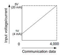
| Analog input | Voltage: 1 to 5 V DC (input impedance: approx. 200 kΩ) | Current: 4 to 20 mA DC (input impedance: approx. 250 kΩ) |
| Communication data (Note 2) | Analogue ⇔ Communication data ・Communication data: 0 to 4,000 digits (within range of 1 to 5 V) ・Zero point: Within 0 digit ±0.5% F.S. (within the range of 1 to 5V) ・Span: Within 4,000 digits ±0.5% F.S. ・Linearity: Within ±0.5% F.S. | Analogu ⇔ Communication data ・Communication data: 0 to 4,000 digits (within range of 4 to 20 mA) ・Zero point: Within 0 digit ±0.5% F.S. ・Span: Within 4,000 digits ±0.5% F.S. ・Linearity: Within ±0.5% F.S. |
| Input | Connectable devices: NPN open-collector transistor output type Current supply for input devices: 100 mA or less Input impedance: 17 kΩ approx. Operating voltage: On voltage of 17 V or more (between input and +V, 24 V applied) Off voltage of 4 V or less (between input and +V, 24 V applied) | |
| Output | NPN open-collector transistor • Maximum sink current: 50 mA or less (when expanding to 5 units or more, 25 mA) • Applied voltage: 30 V DC or less (between output and 0 V) • Residual voltage: 1.5 V or less (with sink current of 50 mA) | |
| Power indicator | Green LED (lights up when the power is ON) | |
| Input indicator | Green LED (lights up when input is being received by unit) | |
| Ambient temperature | –10 to +55 ℃ +14 to +131 ℉ (No dew condensation or icing allowed), (If 4 to 7 units are connected in cascade: –10 to +50 ℃ +14 to +122 ℉, if 8 to 16 units are connected in cascade: –10 to +45 ℃ +14 to +113 ℉) Storage: –20 to +70 ℃ –4 to +158 ℉ | |
| Ambient humidity | 35 to 85% RH, Storage: 35 to 85% RH | |
| Material | Case: Flame-resistant PBT, Connector: Polyester | |
| Weight | Net weight: 15 g approx., Gross weight: 40 g approx. | |
| Accessory | Connector (e-CON): 1 | |
Note:
1) Does not include current consumption or input current for connected input devices.
2) The figure below illustrates the relationship between communication data and input voltage.
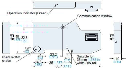
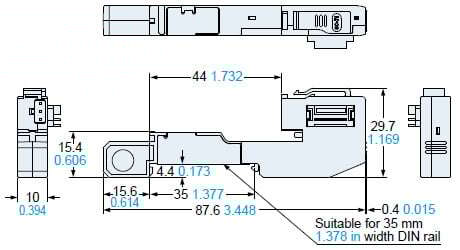
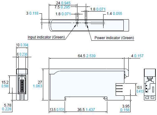
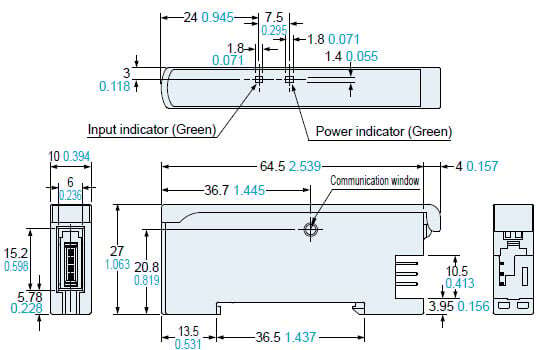
Dimensions
- Unit: mm in
SC-GU3-04
Communication unit for CC-Link IE Field
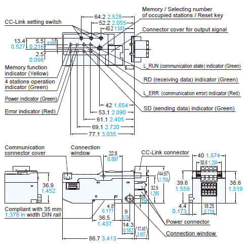
SC-GU3-01
Communication unit for CC-Link
SC-GU3-02 (Discontinued products)
Communication unit for DeviceNet
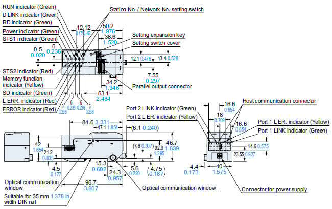
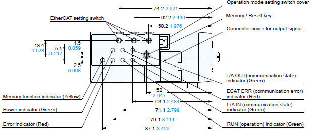
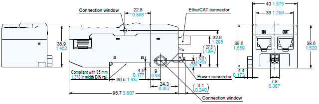
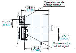
SC-GU3-03
Communication unit for EtherCAT
When an operation mode setting switch cover / a connector cover for output signal is removed
SC-GU3-EU
End unit
SC-71
Cascading connector unit
SC-E1
e-CON 1-channel connector input extension unit
SC-E81
SC-E82
e-CON 8-channel connector input extension unit
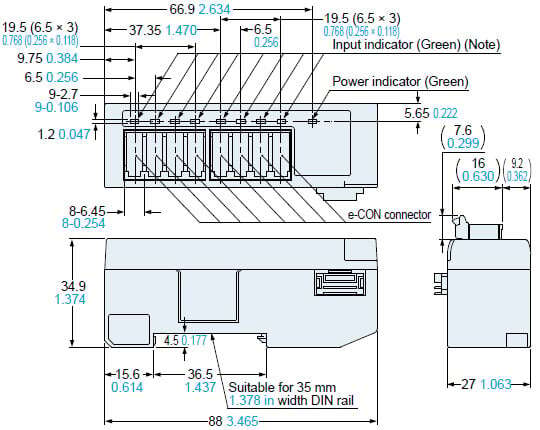
* SC-E82 is not equipped with an input indicator.
SC-A01
SC-A02
Analog input unit
MS-DIN-E
End unit
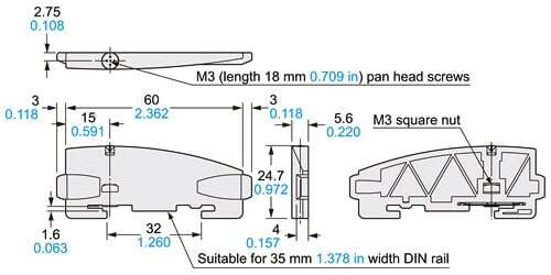
Material:Polycarbonate
Software
- Compatible with Mitsubishi Electric Corporation’s Engineering Software GX Works3 FB (Function Block) for SC-GU3-04 / SC-GU3-01
- Distinguishing SC-GU3-01 versions that support iQSS
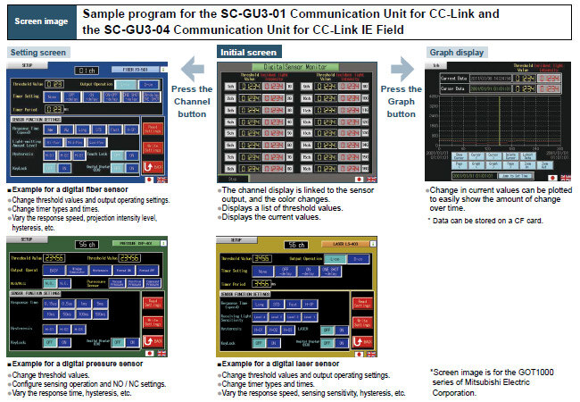
- Sample program for the SC-GU3-01 Communication Unit for CC-Link and the SC-GU3-04 Communication Unit for CC-Link IE Field
Compatible with Mitsubishi Electric Corporation’s Engineering Software GX Works3 FB (Function Block) for SC-GU3-04 / SC-GU3-01
We offer FB (function block) for CC-Link IE Field/CC-Link compatible communication unit SC-GU3-04 / SC-GU3-01 is provide. These FBs are designed to modularize ladder blocks that are repeatedly used within sequence programs, allowing for reuse within the program. By utilizing these FBs, customers can streamline program development, reduce programming errors, and improve and standardize the quality of user programs.

- The FB can be downloaded from the Mitsubishi Electric Corporation website and our company’s website.
>> Communication Unit for Open Network SC-GU3 Software Download - We also offer FBs for the CC-Link IE Field / CC-Link compatible communication units SC-HG1-CEF / SC-HG1-C, for the contact-type digital displacement sensor HG-S series.
>> Communication Unit for Digital Displacement Sensors SC-HG1 Software Download
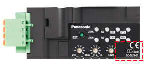
Distinguishing SC-GU3-01 versions that support iQSS
The SC-GU3-01 gained iQSS support starting with units produced in December 2012, at which time the nameplate design was changed as shown below.

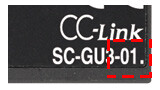
The upgraded model and older models can be distinguished by the period “.” after the model No. (SC-GU3-01) on the bottom right of the nameplate.

Easy configuration of all connected sensors SC-GU3-01 / SC-GU3-04
Not only monitoring current values such as "incident light intensity" and "pressure values" of the digital sensor but also writing sensor setting changes can be performed over the open network.
Program development is simplified by downloading sample programs (screens and ladders) including methods for checking basic threshold and display values as well as basic settings for sensor amplifiers. The sample program's display language can be switched between English and Japanese.
Note:Communications commands are available that enable to check current values and sensor settings also to change settings using CC-Link IE Field / CC-Link.
| Display | PLC | Free downloads |
|---|---|---|
| GOT2000 series (Mitsubishi Electric Corporation) | MELSEC iQ-R series (Mitsubishi Electric Corporation) | Available for download from our website |
SC-GU3-03 version identification
With the version upgrade, the design of the nameplate has been changed as follows.

| Changes in appearance | Supporting Status | |
|---|---|---|
| LS-500 Series | Modular Device Profile (MDP) standard (ETG.5001.1) of EtherCAT standard | |
| Shipment before July 2014 No colon ":" or "V2" after SC-GU3-03
| NO | NO |
| Shipment after August 2014 Colon ":" after SC-GU3-03
| YES | NO |
| Starting with units produced in May 2020(Note) "V2" after SC-GU3-03
| YES | YES |


Note:
For SC-GU3-03 manufactured after May 2020, please use ESI file that supports Modular Device Profile (MDP) standard (ETG.5001.1) of EtherCAT standard.
It cannot be used for SC-GU3-03 manufactured before April 2020.
The ESI file can be downloaded from the website.
* To download the file, you need to register as a web member on the Panasonic Automation Control English (Global) website.
>> Click here to download the ESI file for production after May 2020
SC-GU3-01 version identification
With the version upgrade, the design of the nameplate has been changed as follows.
| Changes in appearance | Supporting Status | |
|---|---|---|
| iQSS | LS-500 Series | |
| Up to units produced in November 2012 No period "." or colon ":" after SC-GU3-01
| NO | NO |
| Starting with units produced in December 2012 Period "." after SC-GU3-01
| YES | NO |
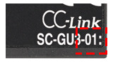
| Shipment after February 2014 Colon ":" after SC-GU3-01
| YES | YES |

SC-GU3-02 version identification
With the version upgrade, the design of the nameplate has been changed as follows.
| Changes in appearance | Supporting Status |
|---|---|
| LS-500 Series | |
| Shipment before April 2014 No colon ":" after SC-GU3-02
| NO |
| Shipment after May 2014 Colon ":" after SC-GU3-02
| YES |