Basic Information
Settings for up to 16 sensors can be changed at once by means of external signals


UL : Recognition
Applications
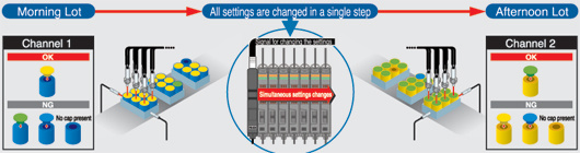
In production lines containing target objects that vary in color from lot to lot, the fiber, sensor's settings must be changed in accordance with the characteristics of the target objects (see illustration below). However, it can be very troublesome to change sensor settings for each different arrangement or type of work. Making these changes to settings takes time and requires extra care, in order to avoid possible malfunctions. The FX-CH series allows preset bank settings to be changed, all in a single step, by utilizing an external signal, without having to handle individual sensors.
Order guide
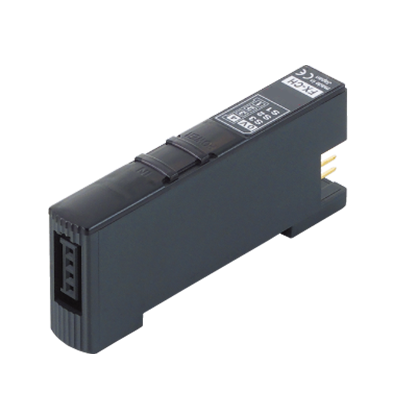
Bank selection units
| Type | Appearance | Model No. | Description |
|---|---|---|---|
| NPN input |
| FX-CH | By using an external signal, this unit can change the bank channel settings for up to 16 sensors [of both the digital laser sensor LS-401(P) and digital fiber sensor FX-301B/G/H(P) (blue / green / infrared)], all in a single step. |
| PNP input | FX-CH-P |
Connectors
| Designation | Appearance | Model No. | Description | |
|---|---|---|---|---|
| 4-pin type snap male connector |
| SL-CP1 (Wihte) [10 pcs. per set] | For 0.08 to 0.2 mm2 (conductor cross-section area) Wire diameter: ø0.7 to ø1.2 mm ø0.028 to ø0.047 in | This snap male connector is used to connect the channel changing input to the bank selection unit. The bank selection unit includes one SL-CP1. |
| SL-CP2 (Black) [10 pcs. per set] | For 0.3 mm2 (conductor cross-section area) Wire diameter: ø1.1 to ø1.6 mm ø0.043 to ø0.063 in | ||
| SL-CP3 (Greenish blue) [10 pcs. per set] | For 0.5 mm2 (conductor cross-section area) Wire diameter: ø1.7 to ø2.5 mm ø0.067 to ø0.098 in | ||


Others
| Designation | Appearance | Model No. | Description |
|---|---|---|---|
| Hook-up pliers for the snap male / female connector |
| SL-JPC | 4-pin type hook-up connectors (SL-CP1, SL-CP2) can be connected in one grip. |
| SL-CP3 exclusive pliers |
| SL-JPE | 4-pin type snap male connector (SL-CP3) can connected in one grip. |


Quick-connection cables
| Type | Model No. | Description | |
|---|---|---|---|
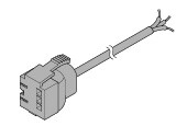
| Main cable for FX-CH(-P) (Note) | CN-73-C1 | Length: 1 m 3.281 ft | This quick-connection cable is utilized when connecting the digital laser sensor LS-401(P) and the digital fiber sensor FX-301B/G/H(P) and the bank selection unit FX-CH(-P) together in side-by-side configuration. 0.15 mm2 3-core cabtyre cable, with connector on one end Cable outer diameter: ø3 mm ø0.118 in |
| CN-73-C2 | Length: 2 m 6.562 ft | ||
| CN-73-C5 | Length: 5 m 16.404 ft | ||
Note :Use a sub cable to connect an amplifier.
Refer to the LS series and FX-301B/G/H for details.
Main cable
CN-73-C□
End plates
| Appearance | Model No. | Description |
|---|---|---|
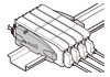
| MS-DIN-E [Two pcs. per set] | After the FX-CH(-P) and the digital laser sensors and the digital fiber sensors have been attached to the DIN rail, all of these devices must be secured firmly together by placing end plates at each of the ends and sandwiching the FX-CH(-P) and the fiber sensors in between. Ensure that these end plates are used for this purpose. |
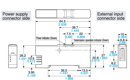
Dimensions
- Unit: mm in
FX-CH FX-CH-P