Basic Information
Highly sensitive manual tuning made easy


CE : EMC Directive
UL : Recognition
Features
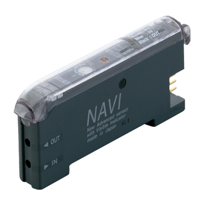
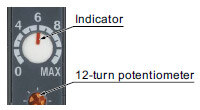
12-turn potentiometer with visible indicator
12-turn potentiometer has been incorporated for fine adjustments. It enables detection of very fine differences. Moreover, since the pointer of indicator has a red backlight, you can confirm the position at a glance, even in a dark area.
Long life and reduced maintenance work-hours
The light-emitting elements of conventional fiber sensors are affected by temperature and long-term use, changing their emission over time and requiring sensitivity readjustment. FX-311 (red LED type) employs the new "four-chemical LED", first used in the FX-301 (red LED type).
This emitter greatly reduces adverse influences on emission performance, resulting in stable operation that almost never needs adjustment.
Rapid flashing "assist function" eases adjustment for optimum sensitivity
The FX-311 series has a convenient built-in "assist function" which indicates the optimum sensitivity position by flashing rapidly when optimum sensitivity is reached. This enables easy and reliable sensitivity adjustment, which is convenient for a narrow sensing range requiring fine tuning.
* In order enable the "assist function", switch the operation selection switch from L-ON→D-ON→L-ON .
Applications
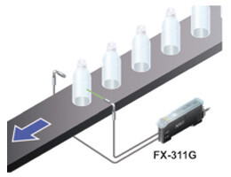
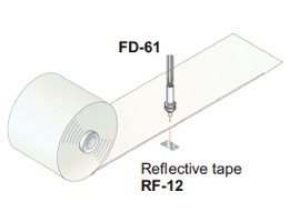
Detecting register marks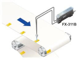
Order guide
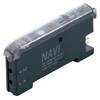
Amplifiers
Quick-connection cable is not supplied with the amplifier. Please order it separately.
Manually set
| Type | Appearance | Model No. | Emitting element | Output |
|---|---|---|---|---|
| NPN output |
| FX-311 | Red LED | NPN open-collector transistor |
| FX-311B | Blue LED | |||
| FX-311G | Green LED | |||
| PNP output | FX-311P | Red LED | PNP open-collector transistor | |
| FX-311BP | Blue LED | |||
| FX-311GP | Green LED |
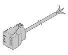
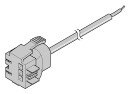
Quick-connection cables
Quick-connection cable is not supplied with the amplifier. Please order it separately.
| Type | Model No. | Description | |
|---|---|---|---|
| Main cable (3-core) | CN-73-C1 | Length: 1 m 3.281 ft | 0.2 mm2 3-core cabtyre cable, with connector on one end Cable outer diameter: ø3.3 mm ø0.130 in |
| CN-73-C2 | Length: 2 m 6.562 ft | ||
| CN-73-C5 | Length: 5 m 16.404 ft | ||
| Sub cable (1-core) | CN-71-C1 | Length: 1 m 3.281 ft | 0.2 mm2 1-core cabtyre cable, with connector on one end Cable outer diameter: ø3.3 mm ø0.130 in |
| CN-71-C2 | Length: 2 m 6.562 ft | ||
| CN-71-C5 | Length: 5 m 16.404 ft | ||
(Note):
The material of Quick-connection cable will be changed from production in March 2013, as soon as the previous ones are shipped out.
・Conductor cross-sectional area has been changed from 0.15mm2 to 0.2mm2.
・Sheath diameter has been changed from ø3.0mm to ø3.3mm.
Main cable
CN-73-C□
Sub cable
CN-71-C□
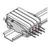
End plates
End plates are not supplied with the amplifier. Please order them separately when the amplifiers are mounted in cascade.
| Appearance | Model No. | Description |
|---|---|---|
| MS-DIN-E | When amplifiers are mounted in cascade, or when an amplifier moves depending on the way it is installed on a DIN rail, these end plates clamp amplifiers into place on both sides. Make sure to use end plates when cascading multiple amplifiers together. Two pcs. per set |
Option
| Designation | Model No. | Description |
|---|---|---|
| Amplifier mounting bracket | MS-DIN-2 | Mounting bracket for amplifier |
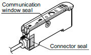
| Fiber amplifier protection seal | FX-MB1 | 10 sets of 2 communication window seals and 1 connector seal Communication window seal: It prevents malfunction due to transmission signal from another amplifier, as well as, prevents effect on another amplifier. Connector seal: It prevents contact of any metal, etc., with the pins of the quickconnection cable. |
Amplifier mounting bracket
MS-DIN-2
Fiber amplifier protection seal
FX-MB1
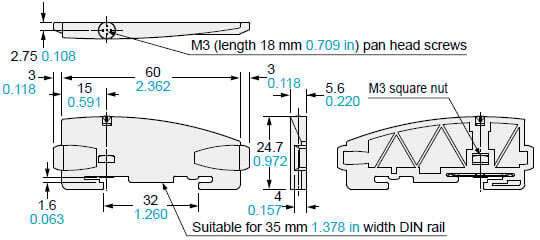
Dimensions
- Unit: mm in
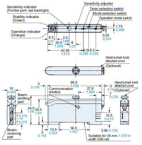
FX-311□
FX-311□P
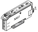
Amplifier
Mounting drawing with a hand-turned knob attached cover FX-AJ1 (Optional)
CN-73-C□
Main cable (Optional)
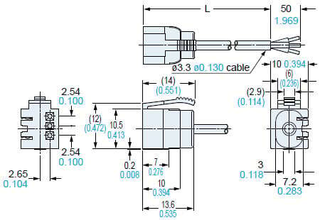
Length L
| Model No. | Length L |
|---|---|
| CN-73-C1 | 1,000 39.370 |
| CN-73-C2 | 2,000 78.740 |
| CN-73-C5 | 5,000 196.850 |
CN-71-C□
Sub cable (Optional)
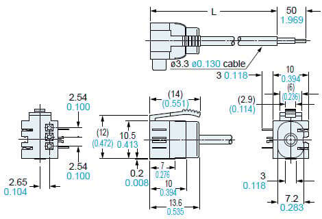
Length L
| Model No. | Length L |
|---|---|
| CN-71-C1 | 1,000 39.370 |
| CN-71-C2 | 2,000 78.740 |
| CN-71-C5 | 5,000 196.850 |
MS-DIN-2
Amplifier mounting bracket (Optional)
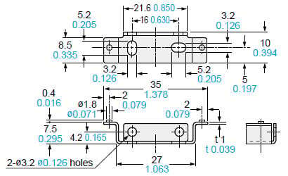
Material: Cold rolled carbon steel (SPCC) (Uni-chrome plated)
MS-DIN-E
End plate (Optional)
Material: Polycarbonate
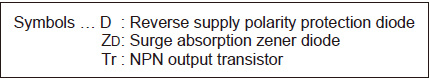
I/O Circuit and Wiring diagrams
FX-311□
NPN output type
I/O circuit diagram
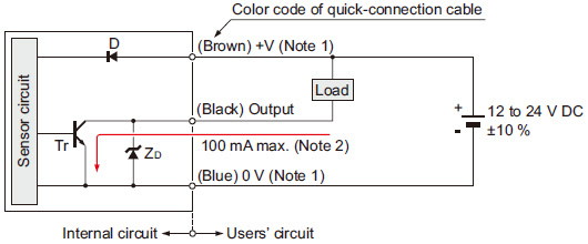
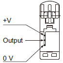
Notes:1):The quick-connection sub cable does not have +V (brown) and 0 V (blue). The power is supplied from the connector of the main cable.2):50 mA max., if five amplifiers, or more, are connected together.
Wiring diagram
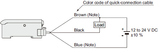
Note:The quick-connection sub cable does not have brown lead wire and blue lead wire. The power is supplied from the connector of the main cable.
Terminal arrangement diagram
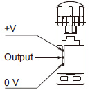
FX-311□P
PNP output type
I/O circuit diagram
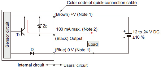
Notes:1):The quick-connection sub cable does not have +V (brown) and 0 V (blue). The power is supplied from the connector of the main cable.2):50 mA max., if five amplifiers, or more, are connected together.
Wiring diagram
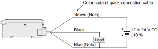
Note:The quick-connection sub cable does not have brown lead wire and blue lead wire. The power is supplied from the connector of the main cable.
Terminal arrangement diagram
Cautions For Use
- Never use this product as a sensing device for personnel protection.
- In case of using sensing devices for personnel protection, use products which meet laws and standards, such as OSHA, ANSI or IEC etc., for personnel protection applicable in each region or country.
Part description
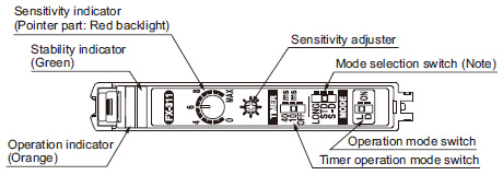
Note: The mode selected by the mode selection switch for FX-311B(P) and FX-311G(P) is 'LONG', 'STD' or 'FAST'.
Amplifier of cascading
・Make sure that the power supply is off while adding or removing the amplifiers.
・Make sure to check the allowable ambient temperature, as it depends on the number of amplifiers connected in cascade.
・In case two, or more, amplifiers are connected in cascade, make sure to mount them on a DIN rail.
・When the amplifiers move on the DIN rail depending on the attaching condition, fitting them between the optional end plates (MS-DIN-E) mounted at the two ends.
・When connecting in cascade, mount the amplifiers close to each other, fitting them between the optional end plates (MS-DIN-E) mounted at the two ends.
・Up to maximum 15 amplifiers can be added (total 16 amplifiers connected in cascade.)
・When connecting more than two amplifiers in cascade, use the sub cable (CN-71-C□) as the quick-connection cable for the second amplifier onwards.
・The settings other than the interference prevention function cannot be transmitted between this product and other digital fiber amplifiers. Therefore, in case both models of amplifiers are mounted in cascade, be sure to mount identical models together.
For more details, refer to "Cautions on sensor connection in cascade".
Timer function
- This product incorporates an OFF-delay timer function. The delay time can be selected as either 10 ms. approx. or 40 ms. approx. with the timer selection switch. Since the output is extended by a fixed period, it is useful when the connected device has a slow response time or when small objects are being sensed and the output signal width is small.
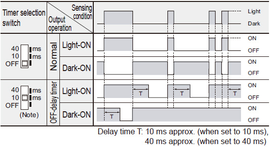
Note: The diagram shows the case when 10 ms delay time is selected.
Automatic interference prevention function
- This product incorporates an automatic interference prevention function. If the amplifiers are mounted in cascade, since a different emission timing is automatically set for up to 4 amplifiers, up to 4 sets of fibers can be mounted closely.
Further, even if the amplifiers are mounted closely along with the digital fiber sensor FX-300 series, the interference prevention function works. However, in case both models of amplifiers are mounted in cascade, mount identical models together.
Wiring
- Make sure that the power supply is off while wiring.
- Verify that the supply voltage variation is within the rating.
- Take care that if a voltage exceeding the rated range is applied, or if an AC power supply is directly connected, the product may get burnt or damaged.
- If power is supplied from a commercial switching regulator, ensure that the frame ground (F.G.) terminal of the power supply is connected to an actual ground.
- In case noise generating equipment (switching regulator, inverter motor, etc.) is used in the vicinity of this product, connect the frame ground (F.G.) terminal of the equipment to an actual ground.
- Take care that short circuit of the load wrong wiring may burn or damage the product.
- Do not run the wires together with high-voltage lines or power lines or put them in the same raceway. This can cause malfunction due to induction.
- Make sure to use an isolation transformer for the DC power supply. If an autotransformer (single winding transformer) is used, this product or the power supply may get damaged.
- Make sure to use the optional quick-connection cable for the connection of the amplifier. Extension up to total 100 m 328.084 ft is possible with 0.3 mm2, or more, cable.
However, in order to reduce noise, make the wiring as short as possible.
Operation procedure
- For FX-311(P), the most suitable sensing mode can be selected according to the application from LONG (long range distance), STD (standard) or S-D (reduced intensity). Furthermore, for FX-311B(P) and FX-311G(P), the sensing mode can be selected from LONG (long range distance), STD (standard) or FAST (high speed sensing).
| Mode selection switch | Applications | Response time | |
|---|---|---|---|
| FX-311(P) | FX-311B(P)/311G(P) | ||
|
| Used in case long distance sensing is required. (However, the response time is longer than in STD mode.) | 2 ms |
|
| Used for general sensing application. | 250 μs |
| - |
| Used in case high speed sensing is required. | 150 μs |
| - | Since the emitted light amount is restricted in this mode, it is suitable for delicate sensing, such as when the received light is saturated due to too short a sensing distance or when detecting translucent objects, etc. | 250 μs |


Note:Make sure to carry out sensitivity adjustment after mode setting.
Sensitivity adjustment
| Sensing condition | Operation | Operation indicator |
|---|---|---|
| Light | L-ON (Light-ON) | Lights up |
| D-ON (Dark-ON) | Turns off | |
| Dark | L-ON (Light-ON) | Turns off |
| D-ON (Dark-ON) | Lights up |
- Adjust the sensitivity, observing the operation indicator (orange).
However, since the condition for lighting up of the indicator depends on the combination of the sensing condition and the selected operation of L/D-ON, verify it from the table below.
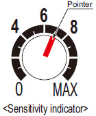
- The sensitivity adjuster is a 12-turn potentiometer. The maximum sensitivity is obtained by turning it fully clockwise.
- The pointer shows the present sensitivity level.
Assist function
Notes:
1)"Assist function" cannot be used when adjusting sensitivity for moving objects.
2)"Assist function" turns off automatically once the sensitivity adjustment has been completed.
3)In case "assist function" is not to be used, set the operation selection switch to D-ON (Dark ON) and wait for 2 sec., or more, to make "assist function" ineffective.
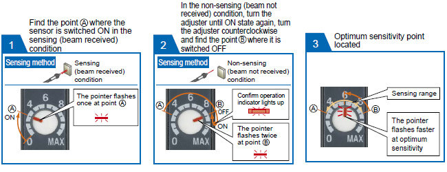
- This product incorporates an "assist function", which helps to easily search the optimum sensitivity position by flashing of the pointer. In order to make "assist function" effective, switch the operation selection switch in the order L-ON (Light ON) → D-ON (Dark ON) → L-ON (Light ON).
| Step | Sensing method | Operation | Sensitivity indicator | |
|---|---|---|---|---|
| Reflective type | Thru-beam type | |||
| (1) | Make sure that the operation selection switch is set to L-ON (Light ON). In case "assist function" is to be used, switch the operation selection switch in the order of L-ON (Light ON) → D-ON (Dark ON) → L-ON (Light ON). | Turn the sensitivity adjuster fully counterclockwise. (Minimum sensitivity) |
| |
| (2) |
Beam received |
Beam received | In the beam received condition, slowly turn the adjuster clockwise and find the point (A) where the sensor is switched ON. The pointer flashes once at the point (A). (Note 1) |
|
| (3) |
Beam not received |
Beam not received | In the beam not received condition, slowly turn the adjuster further clockwise until the sensor goes into the ON state again. Once it is switched on, turn the adjuster counterclockwise a little and find the point (B) where it is switched OFF. The pointer flashes twice at the point (B). (Note 2) (If the sensor does not go into the ON state, MAX is the point (B).) |
|
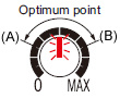
| (4) | - | - | Turn the adjuster towards the point (A) from the point (B) slowly. The pointer starts flashing when it approaches the optimum sensitivity point and flashes faster at the optimum sensitivity point for 3 sec. This point is the optimum sensitivity point. (Note 2) |
|
| (5) | Select either L-ON (Light ON) or D-ON (Dark ON) according to your application. | |||


Notes:
1)When "assist function" is not used, the pointer does not flash.
2)When "assist function" is not used, the middle point of (A) and (B) is regarded as the optimum sensitivity point.
3)In order to protect the mechanism, the sensitivity adjuster idles when over turned, which may result in a backlash of 1 to 2 divisions.
4)Depending upon the sensing conditions, stable sensing may be possible at a position which is slightly shifted from the optimum sensitivity point.
5)Do not move or bend the fiber cable after the sensitivity adjustment. Detection may become unstable.
Others
- Do not use during the initial transient time (0.5 sec. approx.) after the power supply is switched on.
- Take care that the sensor is not directly exposed to fluorescent lamp from a rapid-starter lamp, a high frequency lighting device or sunlight etc. , as it may affect the sensing performance.
- This sensor is suitable for indoor use only.
- Do not use this sensor in places having excessive vapor, dust, etc., or where it may come in contact with corrosive gas.
- Take care that the sensor does not come in contact with water, oil, grease, organic solvents, such as, thinner etc., or strong acid, and alkaline.
- This sensor cannot be used in an environment containing inflammable or explosive gases.
- Never disassemble or modify the sensor.