Basic Information
Constant advances achieving significant improvement of sensing performance


Features
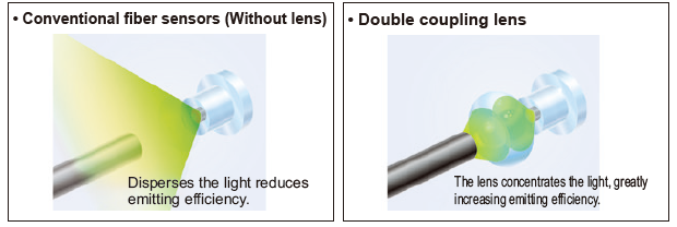
Even greater sensing range
Adoption of a “double coupling lens” that increases emission efficiency to its maximum limits and greatly increases sensing range. Sensing ranges with small diameter fibers and ultrasmall diameter fibers, which have become very popular due to the miniaturization of chip components, have been increased by 50 % over previous values achieved with other amplifiers.
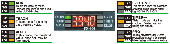
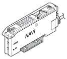
Even beginners can quickly learn how to use the MODE NAVI
MODE NAVI uses six indicators to display the amplifier’s basic operations. The current operating mode can be confirmed at a glance, so even a first time user can easily operate the amplifier without becoming confused.
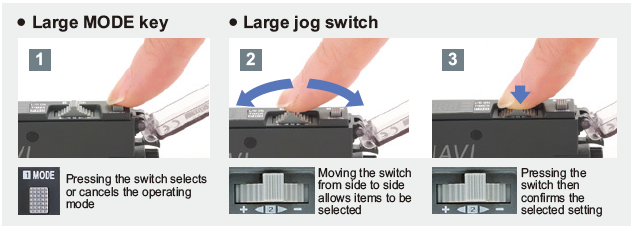
The use of only two switches makes for very simple operations
Only two switches, the large jog switch and the large MODE key, are required for operation. You can operate it simply by the 3 steps shown on the right.
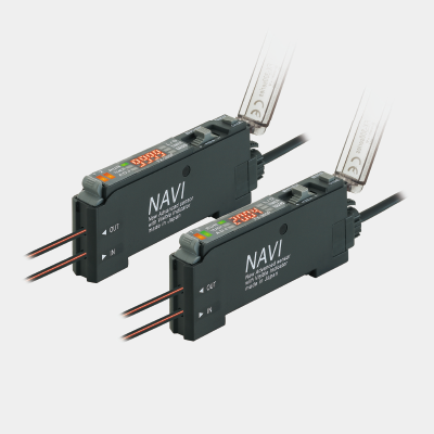
Order guide
Amplifiers
Quick-connection cable is not supplied with the amplififier. Please order it separately.
| Type | Appearance | Model No. | Emitting element | Output |
|---|---|---|---|---|
| Standard type |
| FX-301B | Blue LED | NPN open-collector transistor |
| FX-301BP | PNP open-collector transistor | |||
| FX-301G | Green LED | NPN open-collector transistor | ||
| FX-301GP | PNP open-collector transistor | |||
| FX-301H | Infrared LED | NPN open-collector transistor | ||
| FX-301HP | PNP open-collector transistor |
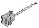
Quick-connection cables For FX-301(-HS)/B/G/H
Quick-connection cable is not supplied with the amplififier. Please order it separately.
| Type | Model No. | Description | |
|---|---|---|---|
| Main cable (3-core) | CN-73-C1 | Length: 1 m 3.281 ft | 0.2 mm2 3-core cabtyre cable with connector on one end Cable outer diameter: ø3.3 mm ø0.130 in |
| CN-73-C2 | Length: 2 m 6.562 ft | ||
| CN-73-C5 | Length: 5 m 16.404 ft | ||
| Sub cable (1-core) | CN-71-C1 | Length: 1 m 3.281 ft | 0.2 mm2 1-core cabtyre cable with connector on one end Cable outer diameter: ø3.3 mm ø0.130 in |
| CN-71-C2 | Length: 2 m 6.562 ft | ||
| CN-71-C5 | Length: 5 m 16.404 ft | ||
Quick-connection cables For FX-305
Quick-connection cable is not supplied with the amplififier. Please order it separately.
| Type | Model No. | Description | |
|---|---|---|---|
| Main cable (4-core) | CN-74-C1 | Length: 1 m 3.281 ft | 0.2 mm2 4-core cabtyre cable with connector on one end Cable outer diameter: ø3.3 mm ø0.130 in |
| CN-74-C2 | Length: 2 m 6.562 ft | ||
| CN-74-C5 | Length: 5 m 16.404 ft | ||
| Sub cable (2-core) | CN-72-C1 | Length: 1 m 3.281 ft | 0.2 mm2 2-core cabtyre cable with connector on one end Cable outer diameter: ø3.3 mm ø0.130 in |
| CN-72-C2 | Length: 2 m 6.562 ft | ||
| CN-72-C5 | Length: 5 m 16.404 ft | ||
(Note):
The material of Quick-connection cable will be changed from production in March 2013, as soon as the previous ones are shipped out.
・Conductor cross-sectional area has been changed from 0.15mm2 to 0.2mm2.
・Sheath diameter has been changed from ø3.0mm to ø3.3mm.
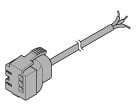
Main cable
CN-73-C□
Sub cable
CN-71-C□

Quick-connection cables For FX-305
Quick-connection cable is not supplied with the amplififier. Please order it separately.
| Type | Model No. | Description | |
|---|---|---|---|
| Main cable (4-core) | CN-74-C1 | Length: 1 m 3.281 ft | 0.2 mm2 4-core cabtyre cable with connector on one end Cable outer diameter: ø3.3 mm ø0.130 in |
| CN-74-C2 | Length: 2 m 6.562 ft | ||
| CN-74-C5 | Length: 5 m 16.404 ft | ||
| Sub cable (2-core) | CN-72-C1 | Length: 1 m 3.281 ft | 0.2 mm2 2-core cabtyre cable with connector on one end Cable outer diameter: ø3.3 mm ø0.130 in |
| CN-72-C2 | Length: 2 m 6.562 ft | ||
| CN-72-C5 | Length: 5 m 16.404 ft | ||
(Note):
The material of Quick-connection cable will be changed from production in March 2013, as soon as the previous ones are shipped out.
・Conductor cross-sectional area has been changed from 0.15mm2 to 0.2mm2.
・Sheath diameter has been changed from ø3.0mm to ø3.3mm.
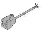
Main cable
CN-74-C□
Sub cable
CN-72-C□
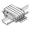
End plates
End plates are not supplied with the amplifier. Please order them separately when the amplifiers are mounted in cascade.
| Appearance | Model No. | Description |
|---|---|---|
| MS-DIN-E | When amplifiers are mounted in cascade, or when an amplifier moves depending on the way it is installed on a DIN rail, these end plates clamp amplifiers into place on both sides. Make sure to use end plates when cascading multiple amplifiers together. Two pcs. per set |
Option
| Designation | Model No. | Description |
|---|---|---|
| Amplifier mounting bracket | MS-DIN-2 | Mounting bracket for amplifier |
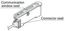
| Fiber amplifier protection seal | FX-MB1 | 10 sets of 2 communication window seals and 1 connector seal Communication window seal: It prevents malfunction due to transmission signal from another amplifier, as well as, prevents effect on another amplifier. Connector seal: It prevents contact of any metal, etc., with the pins of the quick-connection cable. |
Note:Fiber amplifier protection seals are supplied with the FX-301(P) and FX-305(P).
Amplifier mounting bracket
MS-DIN-2
Fiber amplifier protection seal
FX-MB1
Specifications
| Type | Standard type | ||||
|---|---|---|---|---|---|
| Red LED | Blue LED | Green LED | Infrared LED | ||
| Model No. | NPN output | FX-301 | FX-301B | FX-301G | FX-301H |
| PNP output | FX-301P | FX-301BP | FX-301GP | FX-301HP | |
| Supply voltage | 12 to 24 V DC ±10 % Ripple P-P 10 % or less | ||||
| Power consumption | <Red LED / Infrared LED type> Normal operation: 960 mW or less (Current consumption 40 mA or less at 24 V supply voltage) ECO mode: 600 mW or less (Current consumption 25 mA or less at 24 V supply voltage) <Blue LED / Green LED type> Normal operation: 720 mW or less (Current consumption 30 mA or less at 24 V supply voltage) ECO mode: 430 mW or less (Current consumption 18 mA or less at 24 V supply voltage) | ||||
| Output | <NPN output type> NPN open-collector transistor • Maximum sink current:100 mA (50 mA, if five, or more, amplifiers are connected in cascade.) • Applied voltage: 30 V DC or less (between output and 0 V) • Residual voltage: 1.5 V or less [at 100 mA (at 50 mA, if five, or more, amplifiers are connected in cascade) sink current.] <PNP output type> PNP open-collector transistor • Maximum source current: 100 mA (50 mA, if five, or more, amplifiers are connected in cascade.) • Applied voltage: 30 V DC or less (between output and +V) • Residual voltage: 1.5 V or less [at 100 mA (at 50 mA, if five, or more, amplifiers are connected in cascade) source current.] | ||||
| Output operation | Selectable either Light-ON or Dark-ON, with jog switch | ||||
| Short-circuit protection | Incorporated | ||||
| Response time | 65 μs or less [H-SP (Red LED type only)], 150 μs or less (FAST), 250 μs or less [STD / S-D (Red LED type only)], 2 ms or less (LONG), selectable with jog switch | ||||
| Sensitivity setting | 2-point teaching / Limit teaching / Manual adjustment / Full-auto teaching / Max. sensitivity teaching | ||||
| Operation indicator | Orange LED (lights up when the output is ON) | ||||
| Stability indicator | Green LED (lights up under stable light received condition or stable dark condition) | ||||
| MODE indicator | RUN: Green LED, TEACH • ADJ • L/D ON • TIMER • PRO: Yellow LED | ||||
| Digital display | 4 digit red LED display | ||||
| Fine sensitivity adjustment function | Incorporated | ||||
| Timer function | Incorporated with variable ON-delay / OFF-delay / ONE SHOT timer, switchable either effective or ineffective. [Timer period: Red LED type; 0.5 ms approx., 1 to 9,999 ms (Blue LED, Green LED, Infrared LED type; approx. 0.5 to 500 ms)] | ||||
| Light emitting amount selection function | Incorporated (Red LED type only) (Note 3) FAST, STD, LONG: 4 level, H-SP: 3 level, S-D: 2 level | ||||
| Automatic interference prevention function | Incorporated (Up to four sets of fiber heads can be mounted close together. However, 2 fiber heads in H-SP mode.) (Note 4) | ||||
| Ambient temperature | -10 to +55 ℃ +14 to +131 ℉ (If 4 to 7 units are connected in cascade: -10 to +50 ℃ +14 to +122 ℉, if 8 to 16 units are connected in cascade: -10 to +45 ℃ +14 to +113 ℉) (No dew condensation or icing allowed), Storage: -20 to +70 ℃ -4 to +158 ℉ | ||||
| Ambient humidity | 35 to 85 % RH, Storage: 35 to 85 % RH | ||||
| Ambient illuminance | Incandescent light: 3,000 ℓx at the light-receiving face | ||||
| Voltage withstandability | 1,000 V AC for one min. between all supply terminals connected together and enclosure (Note 6) | ||||
| Insulation resistance | 20 MΩ, or more, with 250 V DC megger between all supply terminals connected together and enclosure (Note 6) | ||||
| Vibration resistance | 10 to 150 Hz frequency, 0.75 mm 0.030 in amplitude in X, Y and Z directions for two hours each | ||||
| Shock resistance | 98 m/s2 acceleration (10 G approx.) in X, Y and Z directions for five times each | ||||
| Emitting element (modulated) | Red LED | Blue LED | Green LED | Infrared LED | |
| Peak emission wavelength | 650 nm 0.026 mil | 470 nm 0.019 mil | 525 nm 0.021 mil | 940 nm 0.037 mil | |
| Material | Enclosure: Heat-resistant ABS, Case cover: Polycarbonate, MODE key: Acrylic, Jog switch: Heat-resistant ABS (FX-301B/G/H: Acrylic) | ||||
| Connecting method | Connector (Note 7) | ||||
| Cable length | Total length up to 100 m 328.084 ft (50 m 164.042 ft for 5 to 8 units, 20 m 65.617 ft for 9 to 16 units) is possible with 0.3 mm2, or more, cable. | ||||
| Weight | Net weight: 20 g approx., Gross weight: 25 g approx. | ||||
| Accessory | FX-MB1 (amplifier protection seal): 1 set | - | |||
| Type | High-speed type | High-function type | |
|---|---|---|---|
| Model No. | NPN output | FX-301-HS | FX-305 |
| PNP output | FX-301P-HS | FX-305P | |
| Supply voltage | 12 to 24 V DC ±10 % Ripple P-P 10 % or less | ||
| Power consumption | <Red LED type> Normal operation: 960 mW or less (Current consumption 40 mA or less at 24 V supply voltage) ECO mode: 600 mW or less (Current consumption 25 mA or less at 24 V supply voltage) | ||
| Output | <NPN output type> NPN open-collector transistor • Maximum sink current:100 mA (50 mA, if five, or more, amplifiers are connected in cascade.) • Applied voltage: 30 V DC or less (between output and 0 V) • Residual voltage: 1.5 V or less [at 100 mA (at 50 mA, if five, or more, amplifiers are connected in cascade) sink current.] <PNP output type> PNP open-collector transistor • Maximum source current: 100 mA (50 mA, if five, or more, amplifiers are connected in cascade.) • Applied voltage: 30 V DC or less (between output and +V) • Residual voltage: 1.5 V or less [at 100 mA (at 50 mA, if five, or more, amplifiers are connected in cascade) source current.] | <NPN output type> NPN open-collector transistor 2 outputs • Maximum sink current: 50 mA each (Note 2) • Applied voltage: 30 V DC or less (between output and 0 V) • Residual voltage: 1.5 V or less [at 50 mA (Note 2)] <PNP output type> PNP open-collector transistor 2 outputs • Maximum source current: 50 mA each (Note 2) • Applied voltage: 30 V DC or less (between output and +V) • Residual voltage: 1.5 V or less [at 50 mA (Note 2)] | |
| Output operation | Selectable either Light-ON or Dark-ON, with jog switch | ||
| Short-circuit protection | Incorporated | ||
| Response time | 35 μs or less (H-SP), 150 μs or less (FAST), 250 μs or less (STD / S-D), 2 ms or less (LONG), selectable with jog switch | 65 μs or less (H-SP), 150 μs or less (FAST), 250 μs or less (STD), 700 μs or less (STDF), 2.5 ms or less (LONG), 4.5 ms or less (U-LG), selectable with jog switch | |
| Sensitivity setting | 2-point teaching / Limit teaching / Manual adjustment / Full-auto teaching / Max. sensitivity teaching | Normal mode: 2-point teaching / Limit teaching / Full-auto teaching / Max. sensitivity teaching / Manual adjustment Window comparator mode: Teaching (1-point / 2-point / 3-point) / Manual adjustment | |
| Operation indicator | Orange LED (lights up when the output is ON) | ||
| Stability indicator | Green LED (lights up under stable light received condition or stable dark condition) | - | |
| MODE indicator | RUN: Green LED, TEACH • ADJ • L/D ON • TIMER • PRO: Yellow LED | ||
| Digital display | 4 digit red LED display | ||
| Fine sensitivity adjustment function | Incorporated | ||
| Timer function | Incorporated with variable ON-delay / OFF-delay / ONE SHOT timer, switchable either effective or ineffective. [Timer period: Red LED type; 0.5 ms approx., 1 to 9,999 ms | Incorporated with variable ON-delay / OFF-delay / ONE SHOT / ON-delay • OFF-delay / ON-delay • ONE SHOT timer, switchable either effective or ineffective. (Timer period: Output 1; 0.5 ms, 1 to 9,999 ms, Output 2; 0.5 ms, 1 to 500 ms) | |
| Light emitting amount selection function | Incorporated (Note 3) FAST, STD, LONG: 4 level H-SP, S-D: 2 level | Incorporated (Note 3) FAST, STD, STDF, LONG, U-LG: 4 level H-SP: 3 level | |
| Automatic interference prevention function | - | Incorporated [Up to four sets of fiber heads can be mounted close together. (However, 8 fiber heads in U-LG mode, 2 fiber heads in H-SP mode.)] (Note 5) | |
| Ambient temperature | -10 to +55 ℃ +14 to +131 ℉ (If 4 to 7 units are connected in cascade: -10 to +50 ℃ +14 to +122 ℉, if 8 to 16 units are connected in cascade: -10 to +45 ℃ +14 to +113 ℉) (No dew condensation or icing allowed), Storage: -20 to +70 ℃ -4 to +158 ℉ | ||
| Ambient humidity | 35 to 85 % RH, Storage: 35 to 85 % RH | ||
| Ambient illuminance | Incandescent light: 3,000 ℓx at the light-receiving face | ||
| Voltage withstandability | 1,000 V AC for one min. between all supply terminals connected together and enclosure (Note 6) | ||
| Insulation resistance | 20 MΩ, or more, with 250 V DC megger between all supply terminals connected together and enclosure (Note 6) | ||
| Vibration resistance | 10 to 150 Hz frequency, 0.75 mm 0.030 in amplitude in X, Y and Z directions for two hours each | ||
| Shock resistance | 98 m/s2 acceleration (10 G approx.) in X, Y and Z directions for five times each | ||
| Emitting element (modulated) | Red LED | Red LED | |
| Peak emission wavelength | 650 nm 0.026 mil | 650 nm 0.026 mil | |
| Material | Enclosure: Heat-resistant ABS, Case cover: Polycarbonate, MODE key: Acrylic, Jog switch: Heat-resistant ABS | ||
| Connecting method | Connector (Note 7) | ||
| Cable length | Total length up to 100 m 328.084 ft (50 m 164.042 ft for 5 to 8 units, 20 m 65.617 ft for 9 to 16 units) is possible with 0.3 mm2, or more, cable. | ||
| Weight | Net weight: 20 g approx., Gross weight: 25 g approx. | ||
| Accessory | - | FX-MB1 (amplifier protection seal): 1 set | |
Notes:
1):Where measurement conditions have not been specified precisely, the conditions used were an ambient temperature of +23 ℃ +73.4 ℉.
2):50 mA per output. 25 mA if five, or more, amplifiers are connected in cascade.
3):The light emitting amount can be zero (emission halt) in all modes.
4):When the power supply is switched on, the light emission timing is automatically set for interference prevention.
5):When the interference prevention function " ." is set, the number of mountable fiber heads becomes double.
Furthermore, take care that the response time also becomes double.
6):The voltage withstandability and the insulation resistance values given in the above table are for the amplifier only.
7):The cable for amplifier connection is not supplied as an accessory. Make sure to use the optional quick-connection cables given below.
Main cable (3-core) for FX-301(P)(-HS): CN-73-C1 (Cable length 1 m 3.281 ft), CN-73-C2 (Cable length 2 m 6.562 ft), CN-73-C5 (Cable length 5 m 16.404 ft)
Sub cable (1-core) for FX-301(P)(-HS): CN-71-C1 (Cable length 1 m 3.281 ft), CN-71-C2 (Cable length 2 m 6.562 ft), CN-71-C5 (Cable length 5 m 16.404 ft)
Main cable (4-core) for FX-305(P): CN-74-C1 (Cable length 1 m 3.281 ft), CN-74-C2 (Cable length 2 m 6.562 ft), CN-74-C5 (Cable length 5 m 16.404 ft)
Sub cable (2-core) for FX-305(P): CN-72-C1 (Cable length 1 m 3.281 ft), CN-72-C2 (Cable length 2 m 6.562 ft), CN-72-C5 (Cable length 5 m 16.404 ft)
Dimensions
- Unit: mm in
FX-301□
FX-305(P)
Amplifier
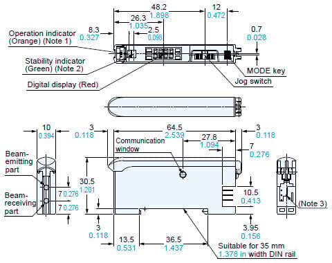
Notes:
1) FX-305□; Output 1 operation indicator (Orange)
2) FX-305□; Output 2 operation indicator (Orange)
3) FX-301□; 3-pin, FX-305□; 4-pin
CN-73-C□
CN-74-C□
Main cable (Optional)
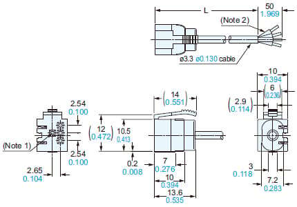
Notes:
1) CN-74-C□ only
2) CN-73-C□; 3-core
• Length L
| Model No. | Length L |
|---|---|
| CN-73/74-C1 | 1,000 39.370 |
| CN-73/74-C2 | 2,000 78.740 |
| CN-73/74-C5 | 5,000 196.850 |
CN-71-C□
CN-72-C□
Sub cable (Optional)
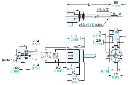
Notes:
1) CN-72-C□ only
2) CN-71-C□: 1-core
• Length L
| Model No. | Length L |
|---|---|
| CN-71/72-C1 | 1,000 39.370 |
| CN-71/72-C2 | 2,000 78.740 |
| CN-71/72-C5 | 5,000 196.850 |
MS-DIN-2
Amplifier mounting bracket (Optional)
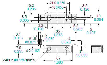
Material: Cold rolled carbon steel (SPCC) (Uni-chrome plated)
MS-DIN-E
End plate (Optional)
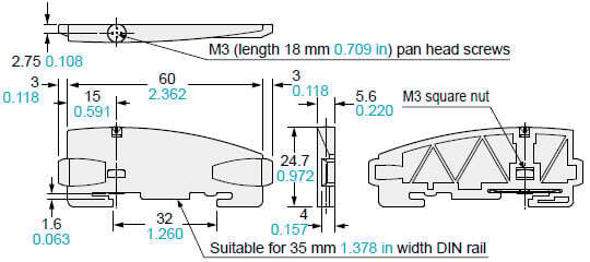
Material: Polycarbonate
・The digital fiber sensor FX-301(P) has been modified since its production in June 2004. The explanations below are about the modified product.
Mounting
How to mount the amplifier
[1]Fit the rear part of the mounting section of the amplifier on a 35 mm 1.378 in width DIN rail.
[2]Press down the rear part of the mounting section of the unit on the 35 mm 1.378 in width DIN rail and fit the front part of the mounting section to the 35 mm 1.378 in width DIN rail.
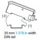
How to remove the amplifier
[1]Push the amplifier forward.
[2]Lift up the front part of the amplifier to remove it.
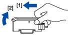
Note:Take care that if the front part is lifted without pushing the amplifier forward, the hook on the rear portion of the mounting section is likely to break.
Fiber installation
・Insert the fiber into the amplifier after attaching the attachment. Refer to the "Instruction Manual" included with the fiber for details.
[1]Push the fiber lock lever down.
[2]Slowly insert the fiber into the insertion slot until it stops. (Note 1)
[3]Push the fiber lock lever back up until it stops.
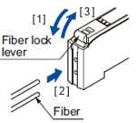
Notes:
1)Note that if the fiber is not fully inserted, the sensing distance will decrease. Also note that the flexible fiber may bend during insertion.
2)In case of coaxial reflective type fibers (FD-G4, FD-FM2, etc.), mount the central fiber (single-core) to the emitter part and the peripheral fiber (multi-core) to the receiver. Note that sensing precision will deteriorate when done in reverse.
Connection
・Make sure that the power supply is off while connecting or disconnecting the quick-connection cable.
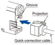
Connection method
[1]Holding the connector of the quick-connection cable, align its projection with the groove at the top portion of the amplifier connector.
[2]Insert the connector till a click is felt.
Disconnection method
[1]Pressing the projection at the top of the quick-connection cable, pull out the connector.
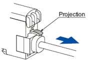
Note:Take care that if the connector is pulled out without pressing the projection, the projection may break. Do not use a quick-connection cable whose projection has broken. Further, do not pull by holding the cable, as this can cause a cable-break.
Cascading
・Make sure that the power supply is off while adding or removing the amplifiers.
・Make sure to check the allowable ambient temperature, as it depends on the number of amplifiers connected in cascade.
・In case two, or more, amplifiers are connected in cascade, make sure to mount them on a DIN rail.
・When the amplifiers move on the DIN rail depending on the attaching condition or the amplifiers are mounted close to each other in cascade, fit them between the optional end plates (MS-DIN-E) mounted at the two ends.
・Up to maximum 15 amplifiers can be added (total 16 amplifiers connected in cascade.)
・When connecting more than two amplifiers in cascade, use the sub cable (CN-71-C□ / CN-72-C□) as the quick-connection cable for the second amplifier onwards.
・When connecting amplifiers not close to each other in parallel, be sure to mount the optional end plate (MS-DIN-E) at both sides of each amplifier or affix the communication window seal of the accessory amplifier protection seal (FX-MB1) to the communication windows.
・The settings other than the interference prevention function cannot be transmitted between FX-301(P) FX-301B/G/H(P), FX-305(P). Therefore, in case both models of amplifiers are mounted in cascade, be sure to mount identical models together. However, the interference prevention function is not incorporated in the FX-301(P)-HS. Take care when the sensors are mounted in cascade.
・If the FX-301(P) updated version unit or the FX-305(P) is mounted with the FX-301(P) previous version unit or the FX-301B/G/H(P) in cascade, place the FX-301(P) updated version units and the FX-305(P) units to the right side (seen from the connector side) of the previous version units. For details, refer to “Cautions on sensor connection in cascade”.
For a difference between the updated version unit and the previous version unit, refer to “A difference between the updated version unit and the previous version unit”.
・The communication function of this product and that of the FX-301(P)-F / F7 is different. If these models are mounted in cascade, affix the accessory fiber amplifier protection seal (FX-MB1) included in the FX-301(P) and FX-305(P) to the communication windows of the amplifiers.
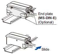
Cascading method
[1]Mount the amplifiers, one by one, on the 35 mm 1.378 in width DIN rail.
[2]Slide the amplifiers next to each other, and connect the quick-connection cables.
[3]Mount the optional end plates (MS-DIN-E) at both the ends to hold the amplifiers between their flat sides.
[4]Tighten the screws to fix the end plates.

Dismantling
[1]Loosen the screws of the end plates.
[2]Remove the end plates.
[3]Slide the amplifiers and remove them one by one.
Cautions on sensor connection in cascade
- When the units in the group A and the group B shown in the table below are connected in cascade, connect them in cascade as <Figure A> shown below.

| Group A | FX-301(P): Previous version unit (Note 1), FX-301G(P)/B(P)/H(P), FX-41□(P), LS-401(P) (Note 2) |
|---|---|
| Group B | FX-301(P): Updated version unit (Note 1), FX-305(P) |
Notes:
1)For the difference between the updated version unit and the previous version unit, refer to “A difference between the updated version unit and the previous version unit”.
2)When LS-401(P) is connected with the digital fiber amplifier in cascade, be sure to locate LS-401(P) at the left-most position (when viewed from the connector side).
- When the units of the group A and the group B are connected in cascade as <Figure B> shown above, optical communications cannot be done. When the optical communications function is used, connect them as <Figure A> shown above. If the units cannot be placed as <Figure A>, the following measure [1] or [2] should be taken.
[1]Affix the communication window seal of the accessory fiber amplifier protection seal (FX-MB1) to the communication window of the FX-301(P) updated version unit or FX-305(P).
[2]If the measure [1] described above cannot be taken, change the optical communications spec. of the group B units.
How to change the communication specification of Group B
- Change the communication specification of Group B according to the following procedures. Make sure to set the communication specification to “
 (Group A communication specification)” or “
 (Optical Communication Stop)”.
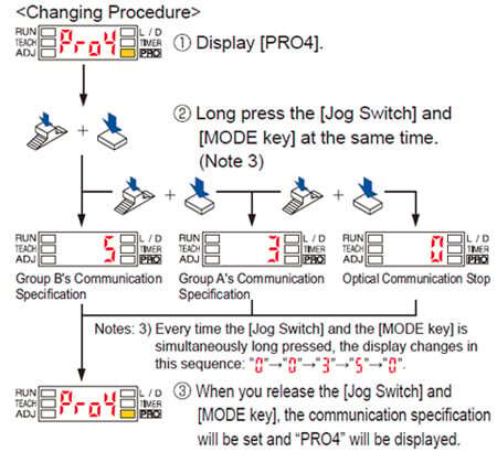
Notes: 4)When the communication specification is set to “![]() (Group A communication specification)”, make sure to tightly attach the products. Also make sure to take note of the following:
(Group A communication specification)”, make sure to tightly attach the products. Also make sure to take note of the following:
・There are instances when the optical communication function cannot be used due to the usage environment, etc.
・Do not perform batch channel loading or saving.
Part description
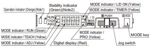
Notes:
1)FX-305(P); Output 1 operation indicator (Orange)
2)FX-305(P); Output 2 operation indicator (Orange)
Operation procedure
- When the power supply is switched on, communication self-check is carried out and normal condition is displayed [MODE indicator / RUN (green)] lights up and the digital display shows the incident light intensity.
- When the MODE key is pressed, the mode will change as shown in the following diagram.
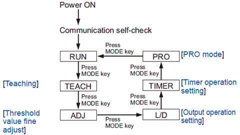
When Jog switch is pressed, the setting is confirmed.When MODE key is pressed for 2 sec., or more, the sensor returns to the ‘RUN’ mode.Cancellation is possible by pressing MODE key during setting.
For FX-305(P)
| The FX-305(P) is equipped with two independent outputs, but the items that can be set in output 1 and output 2 respectively are only the following. The items other than those are common. [1] Threshold value [2] Output operation [3] Timer operation and Timer period [4] Sensing mode |
Teaching
In case of 2-point teaching
- The threshold values can be set by 2-point teaching, limit teaching, full-auto teaching or window comparator mode (1-point, 2-point, 3-point teaching) [only for FX-305(P)], when the MODE indicator / TEACH (yellow) lights up.
- This is the method of setting the threshold value by teaching two levels, corresponding to the object present and object absent conditions. Normally, setting is done by this method.
| Step | Description | Display |
|---|---|---|
| [1] | Set the fiber within the sensing range. Press MODE key to light up MODE indicator / TEACH (yellow).  | |
| [2] | For FX-305(P), select either Output 1 “
| |
| [3] | MODE indicator / TEACH (yellow) blinks.
| |
| [4] | If the teaching is accepted, the read incident light intensity blinks in the digital display and the threshold value is set at the mid-value between the incident light intensities in the object present and the object absent conditions. After this, the judgment on the stability of sensing is displayed. ・In case stable sensing is possible: “ ・In case stable sensing is not possible: “ | |
| [5] | The threshold value is displayed. | |
| [6] | “ (only FX-301B/G/H) | |
| [7] | The incident light intensity appears in the digital display and the setting is complete. |


Notes:
1)Do not move or bend the fiber cable after the sensitivity setting. Detection may become unstable.
2)In case a reflective-type fiber is used, maximum sensitivity will be set if the jog switch is pushed while in no work status in procedure [2] and [3].
In case of full auto-teaching
- Full auto-teaching is used when it is desired to set the threshold value without stopping the assembly line, with the object in the moving condition.
| Step | Description | Display |
|---|---|---|
| [1] | Set the fiber within the sensing range. Press MODE key to light up MODE indicator / TEACH (yellow).  | |
| [2] | For FX-305(P), select either Output 1 “ | |
| [3] | “ | |
| [4] | If the teaching is accepted, the read incident light intensity blinks in the digital display and the threshold value is set at the mid-value between the incident light intensities in the object present and the object absent conditions. After this, the judgment on the stability of sensing is displayed. ・In case stable sensing is possible: “ ・In case stable sensing is not possible: “ | |
| [5] | The threshold value is displayed. | |
| [6] | “ (only FX-301B/G/H) | |
| [7] | The incident light intensity appears in the digital display and the setting is complete. |
Notes:
1)The threshold value’s shift amount can be selected in PRO mode.
Refer to the “PRO Mode Operation Guide” for more details pertaining to setting instructions. (Increments of 5 % between –45 and 45 % for setting possible. 0 % default.)
2)Do not move or bend the fiber cable after the sensitivity setting.
Detection may become unstable.
In case of limit teaching
- This is the method of setting the threshold value by teaching only the object absent condition (stable incident light condition). This is used for detection in the presence of a background body or for detection of small objects.
| Step | Description | Display |
|---|---|---|
| [1] | Set the fiber within the sensing range. Press MODE key to light up MODE indicator / TEACH (yellow).  | |
| [2] | For FX-305(P), select either Output 1 “
| |
| [3] | MODE indicator / TEACH (yellow) blinks. Turn jog switch to the “+” side or “–” side. | |
| [4] | If jog switch is turned to the “+” side, “
If jog switch is turned to the “–” side, “
| |
| [5] | After this, the judgment on whether the setting shift amount can be shifted or not is displayed. ・In case shifting is possible: “ In case shifting is not possible: “ | |
| [6] | The threshold value is displayed. | |
| [7] | “ (only FX-301B/G/H) | |
| [8] | The incident light intensity appears in the digital display and the setting is complete. |


Notes:
1)Scrolling display is not available in FX-301B/G/H.
2)The approx. 15 % amount of shift is the initial value. The amount of shift can be changed in the PRO mode from approx. 5 to 80 % (5 % step). Refer to the “PRO Mode Operation Guide” for more details pertaining to setting instructions.
3)Do not move or bend the fiber cable after the sensitivity setting. Detection may become unstable.
Please download the instruction manual from our website for setting of threshold value when used in combination with liquid level sensing fiber FD-F8Y and with pipe-mountable liquid level sensing fiber FD-F4□. |
For the wind comparator mode teaching in FX-305(P), refer to the separately prepared “PRO Mode Operation Guide”. |
Threshold value fine adjustment
| Step | Description | Display |
|---|---|---|
| [1] | Press MODE key to light up MODE indicator / ADJ (yellow). | |
| [2] | For FX-305(P), select either Output 1 “
In case the threshold value is to be decreased (sensitivity to be increased), turn the jog switch to the “–” side to decrease the threshold value slowly. If the jog switch is turned continuously to the “–” side, the threshold value decreases rapidly.
|  |
| [3] | When jog switch is pressed, the threshold value is confirmed.
|


Output operation setting
| Step | Description | Display |
|---|---|---|
| [1] | Press MODE key to light up MODE indicator / L/D ON (yellow).
|  |
| [2] | For FX-305(P), select either Output 1 “
|  |
| [3] | When jog switch is pressed the threshold value is confirmed.
|  |


Timer operation setting
- The setting for whether the timer is used or not can be done when MODE indicator / TIMER (yellow) lights up. For FX-301B/G/H, the timer type can be set in PRO mode.
- Further, an OFF-delay (initial value) which is useful when the response of the connected device is slow, etc., an ON-delay which is useful to detect only objects taking a long time to travel, and ONE SHOT, which is useful when the input specifications of the connected device require a signal of a fixed width, are possible with the FX-301□(-HS). FX-305(P) is also equipped with ON-delay • OFF-delay and ON-delay • ONE SHOT timers. Refer to the “PRO Mode Operation Guide” for the setting method of the OFF-delay, ON-delay and ONE SHOT timer intervals.
Wiring
- Make sure that the power supply is off while wiring.
- Verify that the supply voltage variation is within the rating.
- Take care that if a voltage exceeding the rated range is applied, or if an AC power supply is directly connected, the product may get burnt or damaged.
- If power is supplied from a commercial switching regulator, ensure that the frame ground (F.G.) terminal of the power supply is connected to an actual ground.
- In case noise generating equipment (switching regulator, inverter motor, etc.) is used in the vicinity of this product, connect the frame ground (F.G.) terminal of the equipment to an actual ground.
- Take care that short circuit of the load wrong wiring may burn or damage the product.
- Do not run the wires together with high-voltage lines or power lines or put them in the same raceway. This can cause malfunction due to induction.
- Make sure to use an isolation transformer for the DC power supply. If an autotransformer (single winding transformer) is used, this product or the power supply may get damaged.
- Make sure to use the optional quick-connection cable for the connection of the amplifier. Extension up to total 100m 328.084 ft is possible with 0.3 mm2, or more, cable. (5-8 unit expansion: 50 m 164.042 ft, 9-16 unit expansion: 20 m 65.617 ft) However, in order to reduce noise, make the wiring as short as possible.
- Note that the residual voltage will increase when the cable is extended.
Key-lock function
Note:3 seconds or more for FX-301B/G/H(P).
- If jog switch and MODE key are pressed for more than 2 sec. at the same time in ‘RUN’ mode condition, the key operations are locked, and only the threshold value confirmation function or the adjust function (valid only when the adjust lock function is canceled) is valid. To cancel the lock function, press both the keys for more than 2 sec. once again.
Others
- When the emission halt of the light emitting amount selection function is set from “OFF” to “ON”, the output may be unstable. Do not use the output control for 0.5 sec. after starting emission.
- Do not use during the initial transient time (0.5 sec.) after the power supply is switched on.
- Take care that the sensor is not directly exposed to fluorescent lamp from a rapid-starter lamp, a high frequency lighting device or sunlight etc. , as it may affect the sensing performance.
- Do not use this sensor in places having excessive vapor, dust, etc., or where it may come in contact with corrosive gas.
- Take care that the product does not come in direct contact with water, oil, grease, or organic solvents, such as, thinner, etc.
- This sensor cannot be used in an environment containing inflammable or explosive gases.
- Never disassemble or modify the sensor.
Function table for FX-300 series
| Previous models | New models | |||||
|---|---|---|---|---|---|---|
| Standard type | High-function type | High-speed type | Standard type | High-speed type | High-function type | |
| FX-301(P) (Previous version unit) | FX-302(P) | FX-303(P) | FX-301(P) (Updated version unit) | FX-301(P)-HS | FX-305(P) | |
| Four-chemical emitting element + APC circuit | No | No | No | Yes | Yes | Yes |
| Four-chemical emitting element only | Yes (Note) | Yes | Yes | – | – | – |
| Light emitting amount selection function | No | No | No | Yes | Yes | Yes |
| Reduced intensity mode (S-D) | Yes (Note) | Yes | No | Yes | Yes | – |
| 9,999 digit display | No | No | No | No | No | Yes |
| Response time (Max. speed) | 150 μs | 300 μs | 90 μs | 65 μs | 35 μs | 65 μs |
| Interference prevention function (Effective no. of units) | Incorporated (4) | Incorporated (8) | Not incorporated (0) | Incorporated (4) | Not incorporated (0) | Incorporated (16) |
| Independent 2 outputs | No | No | No | No | No | Yes |
| Alarm output function | No | No | No | No | No | Yes |
| Error output function | No | No | No | No | No | Yes |
| Differential sensing | No | No | No | No | No | Yes |
| Window comparator mode | No | Yes | No | No | No | Yes |
Peripheral units that can be combined | ||||||
| Bank selection unit FX-CH(-P) | Yes | Yes | No | No | No | No |
| External input unit FX-CH2(-P) | No | No | No | Yes | No | Yes |
| Upper communication unit SC-GU1-485 | No | No | No | Yes | No | Yes |
Note:Except FX-301B/G/H.
A difference between the updated version unit and the previous version unit for FX-301(P) (Red LED type)
Changes in appearance
- The product has been modified as shown below since its production in June 2004.

・
Checking minor changes between previous and updated models can be done by checking whether the printing is on both sides or only one side.
Upgraded functions
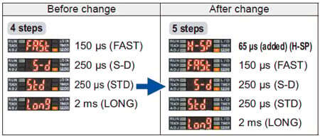
1. Response times added
An ultra high-speed mode (H-SP) has been added to the existing 4 response time modes [high-speed (FAST), reduced intensity (S-D), standard (STD) and long range (LONG)].
This is changed using “![]() ” in “
” in “![]() ”
”
2. Extension of timer period
The setting range for the timer period was previously 500 ms, but this has been extended to a new range of 9,999 ms.
3. Light emitting amount selection function
The light emitting amount can be changed to one of 4 levels (5 levels when emission halt is included).
4. Backup, copy lock and key lock functions added
Backup:This selects whether or not threshold values set by teaching are written to (stored in) an EEPROM.
Copy lock:This selects whether copy function and data bank function communication are possible or not.
Key lock:This disables input using switches to prevent accidental changing of settings.
Changes in operation
1. Timer selection method
Previous version unit:
Timer type was changed using PRO1 mode. The “TIMER” setting in NAVI mode could only be turned on or off.
After change:
The type of timer can be changed using the “TIMER” function in NAVI mode.
2. Checking threshold value in RUN mode
The threshold values can be checked by turning the jog switch.
Display changes
1. Checking blinking of sensitivity surplus
The stable surplus display method after teaching has been changed.
Previous version unit:
Sensitivity surplus is indicated by the number of blinks of the stability indicator.

2. Initial direct code value changed
The factory default settings for the direct codes have been changed.
Previous version unit 0000 → After change 0004
*The default setting for the timer period is 10 ms, and the direct code for 10 ms is “4”, so this has been changed.
Internal circuit changes
1. Addition of an APC circuit
A four-chemical emitting element which provides stable sensing over long periods has been added, as well as an APC () circuit that improves stability during short periods.

Cautions on sensor connection in cascade
When connecting the previous version unit (including FX-301B/G/H) and updated version unit to be used in a cascade, refer to “Cautions on sensor connection in cascade”.
Diagram of functions and settings
The amplifier features and settings are generally classified into two main modes; the “NAVI mode” for items and settings that are frequently reconfigured, and the “PRO mode” that contains more detailed settings
Refer to product catalog or individual instruction manual for details.
Applications
Detecting the presence or absence of labels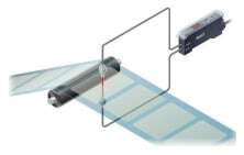
The light-emitting amount selection function can even stabilize detection of transparent labels that saturate the light-receiving level.
Detecting the presence or absence of ICs on a tray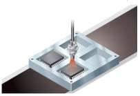
You can set upper and lower limits for the threshold values using the window comparator mode and turn ON / OFF the incident light intensity within that limit.
Detecting the passage of small objects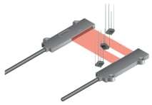
The differential sensing mode will only detect rapid changes in the amount of light, which makes it possible for small objects to be detected.
I/O Circuit and Wiring diagrams
FX-301(-HS)
NPN output type
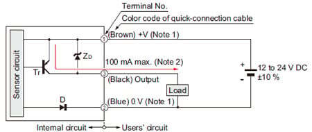
I/O circuit diagram
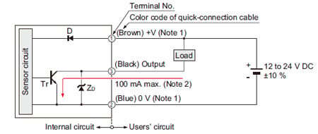
Notes:
1)The quick-connection sub cable does not have +V (brown) and 0 V (blue). The power is supplied from the connector of the main cable.
2)50 mA max., if five amplifiers, or more, are connected together.
Symbols・・・
D : Reverse supply polarity protection diode
ZD: Surge absorption zener diode
Tr: NPN output transistor
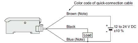
Wiring diagram
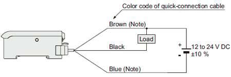
Note:The quick-connection sub cable does not have brown lead wire and blue lead wire.
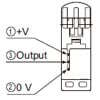
Terminal arrangement diagram
FX-301P(-HS)
PNP output type
I/O circuit diagram
Notes:
1)The quick-connection sub cable does not have +V (brown) and 0 V (blue). The power is supplied from the connector of the main cable.
2)50 mA max., if five amplifiers, or more, are connected together.
Symbols・・・
D : Reverse supply polarity protection diode
ZD: Surge absorption zener diode
Tr: PNP output transistor
Wiring diagram
Note:The quick-connection sub cable does not have brown lead wire and blue lead wire.
Terminal arrangement diagram
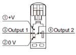
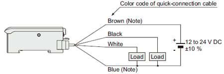
FX-305
NPN output type
I/O circuit diagram
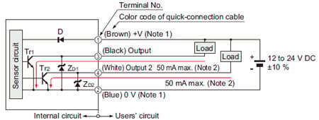
Notes:
1)The quick-connection sub cable does not have +V (brown) and 0 V (blue). The power is supplied from the connector of the main cable.
2)25 mA max., if five amplifiers, or more, are connected together.
Symbols・・・
D : Reverse supply polarity protection diode
ZD1, ZD2: Surge absorption zener diode
Tr1, Tr2: NPN output transistor
Wiring diagram
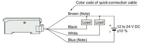
Note:The quick-connection sub cable does not have brown lead wire and blue lead wire.
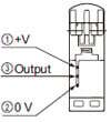
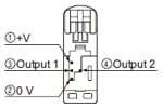
Terminal arrangement diagram
FX-305P
PNP output type
I/O circuit diagram
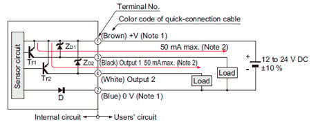
Notes:
1)The quick-connection sub cable does not have +V (brown) and 0 V (blue). The power is supplied from the connector of the main cable.
2)25 mA max., if five amplifiers, or more, are connected together.
Symbols・・・
D : Reverse supply polarity protection diode
ZD1, ZD2: Surge absorption zener diode
Tr1, Tr2: PNP output transistor
Wiring diagram
Note:The quick-connection sub cable does not have brown lead wire and blue lead wire.
Terminal arrangement diagram