Discontinued Products
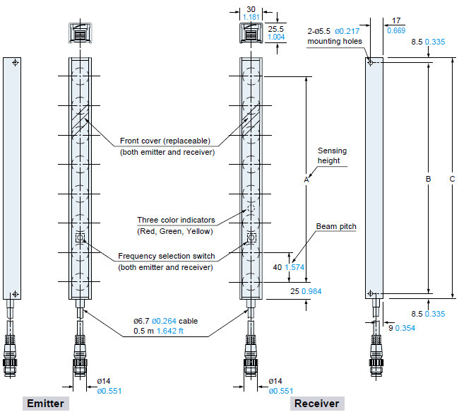
Dimensions
- Unit: mm in
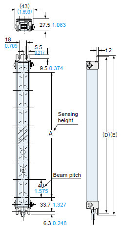
NA40-□
Sensor
| Model No. | A | B | C |
|---|---|---|---|
| NA40-4 | 120 4.724 | 163 6.417 | 180 7.087 |
| NA40-6 | 200 7.874 | 233 9.173 | 250 9.843 |
| NA40-8 | 280 11.024 | 313 12.323 | 330 12.992 |
| NA40-10 | 360 14.173 | 393 15.472 | 410 16.142 |
| NA40-12 | 440 17.323 | 473 18.622 | 490 19.291 |
| NA40-14 | 520 20.472 | 553 21.772 | 570 22.441 |
| NA40-16 | 600 23.622 | 633 24.921 | 650 25.591 |
| NA40-20 | 760 29.921 | 793 31.220 | 810 31.890 |
| NA40-24 | 920 36.220 | 953 37.520 | 970 38.189 |
NA40-□-H
Sensor

| Model No. | A | B | C |
|---|---|---|---|
| NA40-4-H | 120 4.724 | 163 6.417 | 180 7.087 |
| NA40-6-H | 200 7.874 | 233 9.173 | 250 9.843 |
| NA40-8-H | 280 11.024 | 313 12.323 | 330 12.992 |
| NA40-10-H | 360 14.173 | 393 15.472 | 410 16.142 |
| NA40-12-H | 440 17.323 | 473 18.622 | 490 19.291 |
| NA40-14-H | 520 20.472 | 553 21.772 | 570 22.441 |
| NA40-16-H | 600 23.622 | 633 24.921 | 650 25.591 |
| NA40-20-H | 760 29.921 | 793 31.220 | 810 31.890 |
| NA40-24-H | 920 36.220 | 953 37.520 | 970 38.189 |
MS-NA40-1
Sensor mounting bracket (Accessory)
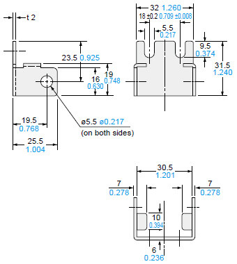
Material:Cold rolled carbon steel (SPCC) (Uni-chrome plated)
Four bracket set
[4 pcs. each of M5 (length 40 mm1.575 in) truss head screws, nuts and spring washers are attached.]
Assembly dimensions
Mounting drawing with NA40-□.
The assembly for the spatter protection hood type (NA40-□-H) is similar.
| Model No. | A | D | E |
|---|---|---|---|
| NA40-4(-H) | 120 4.724 | 200 7.874 | 210 8.268 |
| NA40-6(-H) | 200 7.874 | 270 10.630 | 280 11.024 |
| NA40-8(-H) | 280 11.024 | 350 13.780 | 360 14.173 |
| NA40-10(-H) | 360 14.173 | 430 16.929 | 440 17.323 |
| NA40-12(-H) | 440 17.323 | 510 20.079 | 520 20.472 |
| NA40-14(-H) | 520 20.472 | 590 23.228 | 600 23.622 |
| NA40-16(-H) | 600 23.622 | 670 26.378 | 680 26.772 |
| NA40-20(-H) | 760 29.921 | 830 32.677 | 840 33.071 |
| NA40-24(-H) | 920 36.220 | 990 38.976 | 1,000 39.370 |
SF-IND
Large indicator for area sensor (Optional)
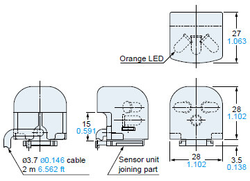
Assembly dimensions
Mounting drawing with NA40-□.
The assembly for the spatter protection hood type (NA40-□-H) is similar.
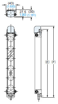
| Model No. | E | F |
|---|---|---|
| NA40-4(-H) | 210 8.268 | 223 8.780 |
| NA40-6(-H) | 280 11.024 | 293 11.535 |
| NA40-8(-H) | 360 14.173 | 373 14.685 |
| NA40-10(-H) | 440 17.323 | 453 17.835 |
| NA40-12(-H) | 520 20.472 | 533 20.984 |
| NA40-14(-H) | 600 23.622 | 613 24.134 |
| NA40-16(-H) | 680 26.772 | 693 27.283 |
| NA40-20(-H) | 840 33.071 | 853 33.583 |
| NA40-24(-H) | 1,000 39.370 | 1,013 39.882 |
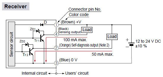
I/O Circuit and Wiring diagrams
I/O circuit diagrams
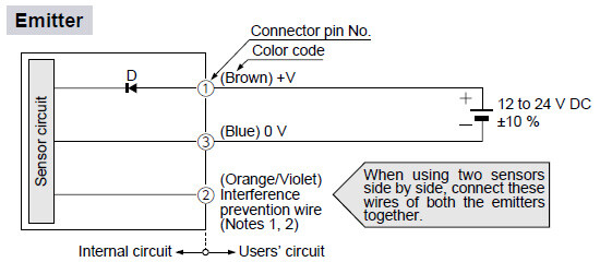

Notes:
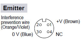
1)If the interference prevention wires (orange/violet) are not used, please insulate them.
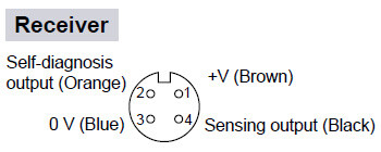
2)Never connect the emitter's interference prevention wire (orange/violet) to the receiver's self-diagnosis output (orange).This can cause damage.
Connector pin position