Basic Information
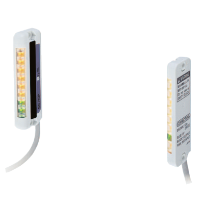
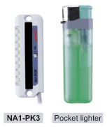
Boasts a compact, pocket lighter size enabling universal installation


Space-saving, pocket lighter-sized unit
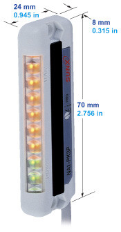
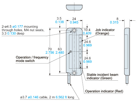
Ultra compact size: W24 x H70 x D8 mm W0.945 x H2.756 x D0.315 in.
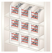
Can even be mounted within the small space constraints of parts containers.
Utilizes a large, bright, clearly visible job indicator
The ultra compact body incorporates a job indicator approx. 50 mm 1.969 in tall.
Due to its brightness and high visibility, it is now possible to check sensor operation even from a distance.
No synchronization wires required
Synchronization wires are not required, due to the utilization of a synchronized scanning system that results in a reduction of wiring man-hours. In addition, the sensors can be switched among three different emission frequencies, allowing up to three sets of sensors to be installed closely together in the same vertical plane, without causing mutual interference. Even when installed in multistage shelving, malfunctions due to mutual interference will not occur. (When mounted horizontally, a maximum of two sensor sets may be used side-by-side, without interference.)
Switchable output operation
Output operation can be switched to suit the desired application.
Sensor protection brackets are available
Sensor protection brackets are now available (optional), to protect sensors from damage due to tools and other objects. The protection brackets have a black coating, which enhances the visual effectiveness of the job indicator.

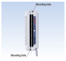
Easy alignment
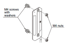
The sensor's beam axis is directly in line with the mounting holes, making sensor alignment easier.
Mounting can be performed simply by using M4 nuts.
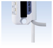
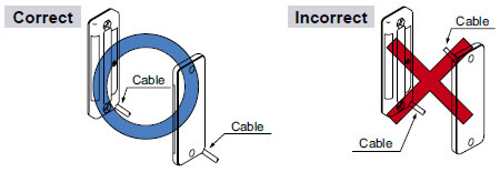
Flexible cable orientation
The cabling can be oriented in either of the two different directions: downward or sideways, thus permitting a flexible layout, in accordance with the sensor's mounting position.


Order guide
| Type | Appearance | Sensing range (Note 1) | Model No. (Note 2) | Output |
|---|---|---|---|---|
| NPN output |
| 30 to 300 mm 1.181 to 11.811 in | NA1-PK3 | NPN open-collector transistor |
| PNP output | NA1-PK3-PN | PNP open-collector transistor |
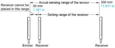
Note 1 :
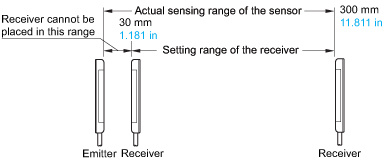
The sensing range is the possible setting distance between the emitter and the receiver.
Note 2 :
The model No. with "P" shown on the label affixed to the product is the emitter, "D" shown on the label is the receiver.
5 m 16.404 ft cable length type, pigtailed type
5 m 16.404 ft cable length type (standard: 2 m 6.562 ft) and pigtailed type (standard: cable type) are also available.
・Table of Model Nos.
| Type | Standard type | 5 m 16.404 ft cable length type | Pigtailed type (Note) |
|---|---|---|---|
| NPN output | NA1-PK3 | NA1-PK3-C5 | NA1-PK3-J |
| PNP output | NA1-PK3-PN | NA1-PK3-PN-C5 | NA1-PK3-PN-J |
Note :
Please order the suitable mating cable separately for pigtailed type.
・Mating cable (2 cables are required.)

Option
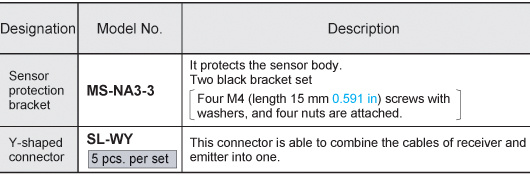
| Designation | Model No. | Description |
|---|---|---|
| Sensor protection bracket | MS-NA3-3 | It protects the sensor body. Two black bracket set [Four M4 (length 15 mm 0.591 in) screws with washers, and four nuts are attached.] |
| Y-shaped connector | SL-WY [5 pcs. per set] | This connector is able to combine the cables of receiver and emitter into one. |
Sensor protection bracket
MS-NA3-3
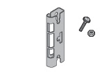
Two bracket set Four M4 (length 15 mm0.591 in) screws with washers, and four nuts are attached.
Y-shaped connector
SL-WY

センサ保護金具
MS-NA3-3
金具2個1セット
[M4(長さ15mm)座金組込ビス4本、ナット4個付属]
Y型コネクタ
SL-WY
Specifications
| Type | NPN output | PNP output | |
|---|---|---|---|
| Model No. | NA1-PK3 | NA1-PK3-PN | |
| Applicable regulations | CE Marking (EMC Directive, RoHS Directive), UKCA Marking (EMC Regulations, RoHS Regulations) | ||
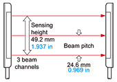
| Sensing height | 49.2 mm 1.937 in | ||
| Sensing range (Note 2) | 30 to 300 mm 1.181 to 11.811 in | ||
| Beam pitch | 24.6 mm 0.969 in | ||
| Number of beam channels | 3 beam channels | ||
| Sensing object | ø29 mm ø1.142 in or more opaque object (completely beam interrupted object) | ||
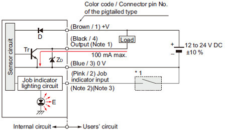
| Supply voltage | 12 to 24 V DC ± 10 % Ripple P-P 10 % or less | ||
| Current consumption | Emitter: 30 mA or less, Receiver: 50 mA or less | ||
| Output | NPN open-collector transistor ・ Maximum sink current: 100 mA ・ Applied voltage: 30 V DC or less (between output and 0 V) ・ Residual voltage: 1 V or less (at 100 mA sink current) 0.4 V or less (at 16 mA sink current) | PNP open-collector transistor ・ Maximum source current: 100 mA ・ Applied voltage: 30 V DC or less (between output and +V) ・ Residual voltage: 1 V or less (at 100 mA source current) 0.4 V or less (at 16 mA source current) | |
| Utilization category | DC-12 or DC-13 | ||
| Output operation | ON or OFF when one or more beam channels are interrupted, selectable by operation mode switch | ||
| Short-circuit protection | Incorporated | ||
| Response time | 10 ms or less (when interference prevention function is used: 30 ms or less) | ||
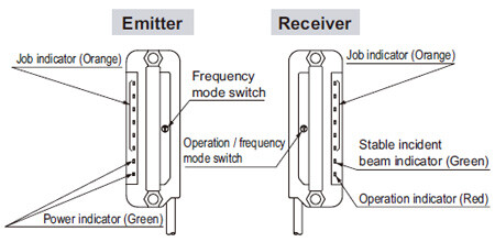
| Indicators | Emitter | Power indicator: Green LED (lights up when the power is ON) Job indicator: Orange LED (lights up when the job indicator input is Low) | Power indicator: Green LED (lights up when the power is ON) Job indicator: Orange LED (lights up when the job indicator input is High) |
| Receiver | Operation indicator: Red LED (lights up when the output is ON) Stable incident beam indicator: Green LED (lights up when all beam channels are stably received) Job indicator: Orange LED (lights up when the job indicator input is Low) | Operation indicator: Red LED (lights up when the output is ON) Stable incident beam indicator: Green LED (lights up when all beam channels are stably received) Job indicator: Orange LED (lights up when the job indicator input is High) | |
| Interference prevention function | Incorporated (Up to 3 units can be mounted close together.) | ||
| Pollution degree | 3 (Industrial environment) | ||
| Protection | IP62 (IEC) | ||
| Ambient temperature | -10 to +55 ℃ +14 to +131 ℉ (No dew condensation or icing allowed), Storage: -20 to +70 ℃ -4 to +158 ℉ | ||
| Ambient humidity | 35 to 85 % RH, Storage: 35 to 85 % RH | ||
| Ambient illuminance | Incandescent light: 3,000 lx or less at the light-receiving face | ||
| Voltage withstandability | 1,000 V AC for one min. between all supply terminals connected together and enclosure | ||
| Insulation resistance | 20 MΩ, or more, with 250 V DC megger between all supply terminals connected together and enclosure | ||
| Vibration resistance | 10 to 150 Hz frequency, 0.75 mm 0.030 in (5 G max.) double amplitude in X, Y and Z directions for two hours each | ||
| Shock resistance | 500 m/s2 acceleration (50 G approx.) in X, Y and Z directions three times each | ||
| Emitting element | Infrared LED (synchronized scanning system) | ||
| Material | Enclosure: Heat-resistant ABS, Lens cover: Acrylic, Indicator cover: Acrylic | ||
| Cable | 0.2 mm2 4-core (emitter: 3-core) oil resistant cabtyre cable, 2 m 6.562 ft long | ||
| Cable extension | Extension up to total 100 m 328.084 ft is possible for both emitter and receiver with 0.3 mm2 , or more, cable. | ||
| Net weight | Emitter: 50 g approx., Receiver: 50 g approx. | ||
Note 1 :
Where measurement conditions have not been specified precisely, the conditions used were an ambient temperature of +23 ℃ +73.4 ℉.
Note 2 :
The sensing range is the possible setting distance between the emitter and the receiver.
Dimensions
- Unit: mm in
NA1-PK3 NA1-PK3-PN
Sensor
Emitter
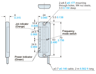
Receiver
MS-NA3-3
Sensor protection bracket (Optional)
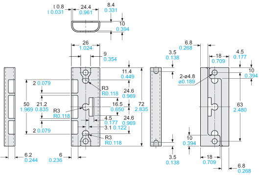
Material:Cold rolled carbon steel (SPCC) (Black chromate)Two bracket set[Four M4 (length 15 mm0.591 in) screws with washers and four nuts are attached.]Note:The sensor protection bracket can be used for both the emitter and the receiver.
I/O Circuit and Wiring diagrams
NPN output type
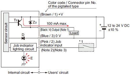
I/O circuit diagram
Notes:
1) The emitter does not incorporate the output (black).
2) If a mating cable is connected to the pigtailed type, then the lead wire color is “white”.
3) When the job indicator is used as a large size operation indicator, connect the job indicator input wire (pink) of the emitter and the receiver to the output wire (black) of the receiver.
Symbols・・・
D : Reserve supply polarity protection diode
ZD: Surge absorption zener diode
Tr : NPN output transistor
E : Job indicator (IND.)
Connector pin position (Pigtailed type)
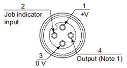
Notes:
1) No connection is required for the emitter.
2) The pin position for the SL-WY Y-shaped connector (optional) is identical to the receiver.
PNP output type
I/O circuit diagram
Notes:
1) The emitter does not incorporate the output (black).
2) If a mating cable is connected to the pigtailed type, then the lead wire color is “white”.
3) When the job indicator is used as a large size operation indicator, connect the job indicator input wire pink) of the emitter and the receiver to the output wire (black) of the receiver.
Symbols・・・
D : Reserve supply polarity protection diode
ZD: Surge absorption zener diode
Tr: PNP output transistor
E : Job indicator (IND.)
Connector pin position (Pigtailed type)
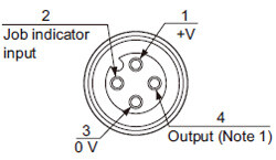
Notes:
1) No connection is required for the emitter.
2) The pin position for the SL-WY Y-shaped connector (optional) is identical to the receiver.
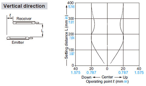
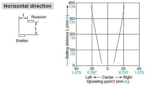
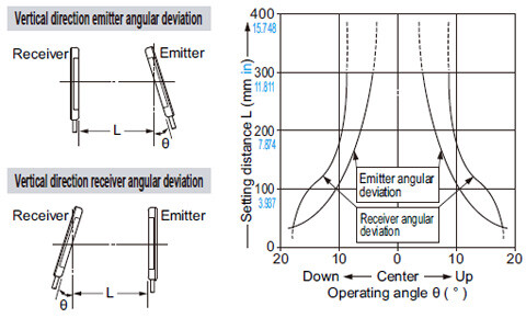
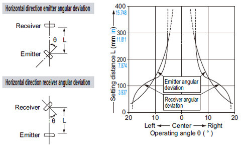
Sensing characteristics
*TYPICAL
Parallel deviation
Angular deviation
Part description
Mounting
- Use M4 screws with washers and M4 nuts. The tightening torque should be 0.5 N·m or less.
(Purchase the screws and nuts separately.)
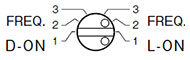
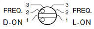
Selection of operation
- The output operation can be selected by the operation / frequency selection switch on the receiver.
(Make sure that the power supply is off while setting the selection switch.)
| State of operation / frequency selection switch | Output operation | |
|---|---|---|
| L-ON |
| OFF when one or more beams are interrupted. |
| D-ON |
| ON when one or more beams are interrupted. |
Notes:
1) Selection of the output operation and the frequency for the receiver is carried out with the same switch. When the output operation is set, be sure to select the same frequency No. of the emitter and the receiver.
2) In case the operation / frequency selection switch is set to the position other than 1, 2 or 3, the state of the receiver is in D-ON / frequency 1.
Orientation
- The emitter and the receiver must face each other correctly.
If they are set upside down, the sensor does not work.
Interference prevention function
- By setting different emission frequencies, three units of NA1-PK3 can be mounted close together, as shown in the figure on the below.

- However, if the sensors are mounted close together as shown in the figure below, up to 2 sets of sensors are possible.
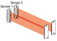
Frequency setting
- Set the both emitting and receiving frequency of Sensor 1 to FREQ. 1, the both emitting and receiving frequency of Sensor 2 to FREQ. 2 and the both emitting and receiving frequency of Sensor 3 to FREQ. 3.
(Make sure that the power supply is off while setting the selection switch.)

Notes:
1) Take care that selection of the output operation and the frequency for the receiver is carried out with the same switch.
2) In case the frequency switch and the operation / frequency selection switch is set to the position other than 1, 2 or 3, the state of the emitter is in frequency 1 and that of the receiver is in D-ON / frequency 1.
Wiring
- Make sure that the power supply is off while wiring and setting the selection switch.
- Take care that wrong wiring may damage the sensor.
- Verify that the supply voltage variation is within the rating.
- If power is supplied from a commercial switching regulator, ensure that the frame ground (F.G.) terminal of the power supply is connected to an actual ground.
- In case noise generating equipment (switching regulator, inverter motor, etc.) is used in the vicinity of the sensor, connect the frame ground (F.G.) terminal of the equipment to an actual ground.
- Extension up to total 100 m 328.084 ft is possible with 0.3 mm2, or more, cable for both emitter and receiver.
However, in order to reduce noise, make the wiring as short as possible. - Do not run the wires together with high-voltage lines or power lines or put them in the same raceway. This can cause malfunction due to induction.
- Make sure to use an isolation transformer for the DC power supply. If an auto-transformer (single winding transformer) is used, this product or the power supply may get damaged.
- In case a surge is generated in the used power supply, connect a surge absorber to the supply and absorb the surge.
Others
- This product has been developed / produced for industrial use only.
- Do not use during the initial transient time (0.5 sec.) after the power supply is switched on.
- Take care that the sensor is not directly exposed to fluorescent light from a rapid-starter lamp or a high frequency lighting device, as it may affect the sensing performance.
- Avoid dust, dirt, and steam.
- Take care that the product does not come in direct contact with water, oil, grease or organic solvents, such as, thinner, etc.
- To select the switch, a minus screwdriver is necessary.
(Tip dimension: 2.5 × 0.6 mm 0.098 × 0.024 in) - These sensors are only for indoor use.