Discontinued Products

Dimensions
- Unit: mm in
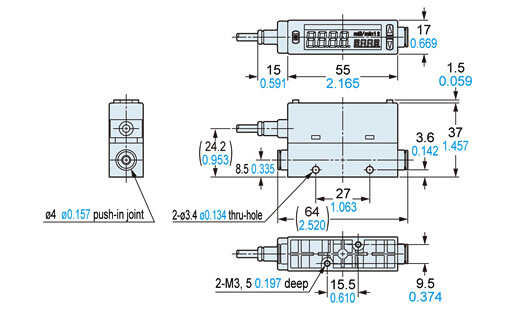
FM-2□-4(-P)
Sensor
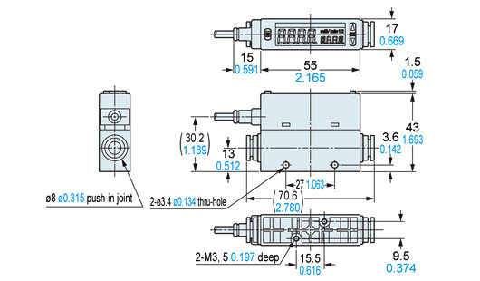
FM-2□-8(-P)
Sensor
FM-2□-A□(-P)
Sensor
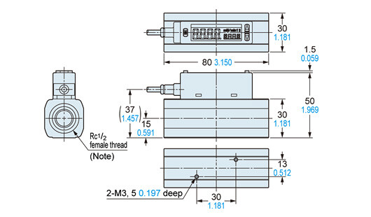
Note: FM-2□-AG2-P has G1/2female thread.
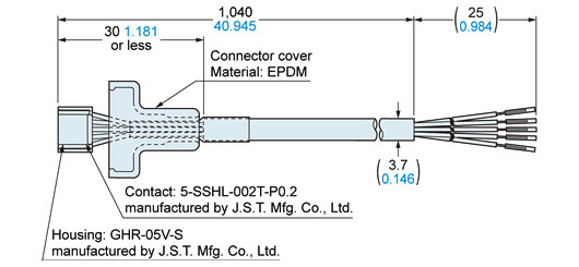
CN-F15-C1
Connector attached cable (Optional)
MS-FM2-1
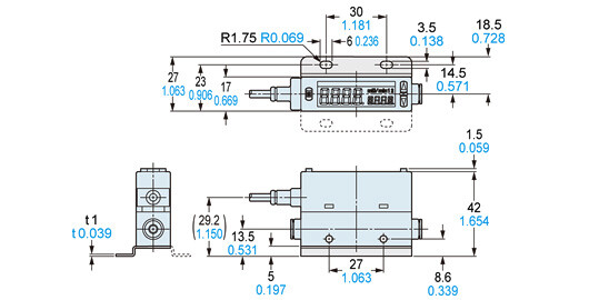
Sensor mounting bracket (Optional)
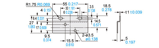
Material:Cold rolled carbon steel (SPCC) (Nickel plated)Two M3 (length 6 mm0.236 in) screws with washers are attached.
Assembly dimensions
Mounting drawing with FM-252-4
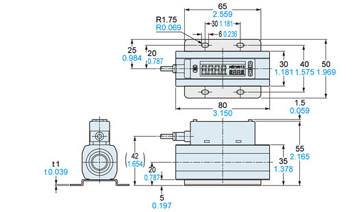
MS-FM2-2
Sensor mounting bracket (Optional)
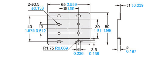
Material:Cold rolled carbon steel (SPCC) (Nickel plated)Two M3 (length 6 mm0.236 in) screws with washers are attached.
Assembly dimensions
Mounting drawing with FM-255-AR2
I/O Circuit and Wiring diagrams
FM-2□
NPN output type
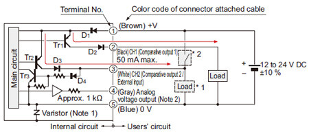
I/O circuit diagram
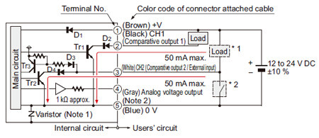
Notes:
1)
As for the aluminum body type, varistor (clamping voltage approx. 40 V) is connected between the internal power circuit and the metal body to prevent breakdown of the sensor. Connect the metal body to +V of power supply or to frame ground (F.G.) of a device that is connected to 0 V. High potential and insulation resistance tests between the internal power circuit and the metal body must not be done.
2)
Short-circuit protection is not incorporated into the analog voltage output. Do not connect the power supply or capacitive load directly to the analog voltage output.
Symbols・・・
D1 to D4 : Reverse supply polarity protection diode
Tr1,Tr2 : NPN output transistor
Tr3 : PNP input transistor
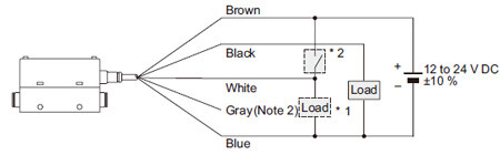
Wiring diagram
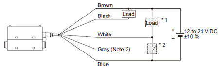
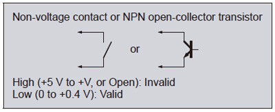
*1: When using CH2 as a comparative output 2
*2: When using CH2 as an external input
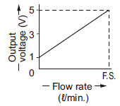
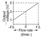
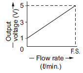
Analog voltage output
<Bi-direction detection>
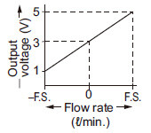
<One-side detection>
FM-2□-P
PNP output type
I/O circuit diagram
Notes:
1)
As for the aluminum body type, varistor (clamping voltage approx. 40 V) is connected between the internal power circuit and the metal body to prevent breakdown of the sensor. Connect the metal body to +V of power supply or to frame ground (F.G.) of a device that is connected to 0 V. High potential and insulation resistance tests between the internal power circuit and the metal body must not be done.
2)
Short-circuit protection is not incorporated into the analog voltage output. Do not connect the power supply or capacitive load directly to the analog voltage output.
Symbols・・・
D1 to D4 : Reverse supply polarity protection diode
Tr1,Tr2 : PNP output transistor
Tr3 : NPN input transistor
Wiring diagram
*1: When using CH2 as a comparative output 2
*2: When using CH2 as an external input

Analog voltage output
<Bi-direction detection>
<One-side detection>
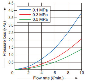
Sensing characteristics
FM-252-4(-P)
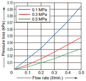
FM-213-4(-P)
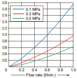
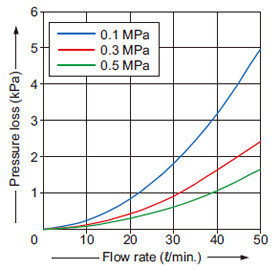
FM-253-4(-P)
FM-214-4(-P)
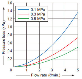
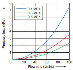
FM-254-8(-P)
FM-215-8(-P)
FM-255-A□2(-P)
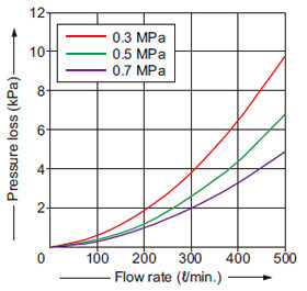
FM-216-A□2(-P)
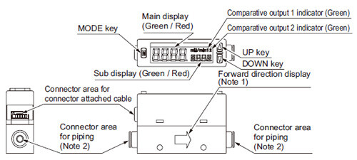
Part description
Notes:
1)Direction of the arrow indicates the forward direction of flow rate when setting the flow direction to bi-direction or one-side forward direction. When setting the flow direction to one-side reverse direction, a direction opposite to the forward direction display will be the forward direction of the flow rate.
2)ø4 mm ø0.157 in push-in joint / ø8 mm ø0.315 in push-in joint is incorporated in FM-2□-4 (-P) / FM-2□-8 (-P), respectively. The push-in joint is not incorporated in the aluminum body type.
Terminal arrangement diagram
Terminal arrangement of the connectors of this product
(sensor body)
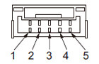
| Connector pin No. | Color code of the connector attached cable | Terminal |
|---|---|---|
| 1 | Brown | +V |
| 2 | Black | CH1 (comparative output 1) |
| 3 | White | CH2 (comparative output 2 / external input) |
| 4 | Gray | Analog voltage output |
| 5 | Blue | 0 V |
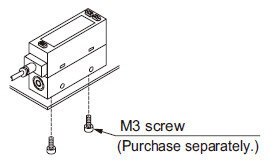
Mounting
Horizontal mounting
- This product can be installed facing up or down or to the left or right.
<Resin body type>
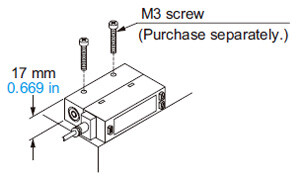
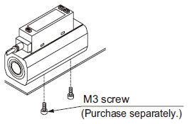
Vertical mounting
- Use M3 screws, and the tightening torque should be 0.5 N·m.
<Resin body type>
<Aluminum body type>
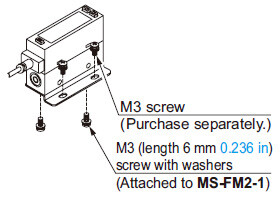
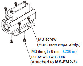
When using sensor mounting bracket
- When mounting the product on the sensor mounting bracket MS-FM2-1 (optional) or MS-FM2-2 (optional), use the M3 screws (length 6 mm 0.236 in) attached to the sensor mounting bracket. The tightening torque should be 0.5 N·m. Use M3 screws to mount the sensor mounting bracket on a sensing surface.
<Resin body type>
Use MS-FM2-1
Use MS-FM2-2
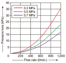
Piping
| Material of tube | Tube diameter (mm in) | Allowable diameter |
|---|---|---|
| Polyamide | ø4 ø0.157, ø8 ø0.315 | Within ±0.1 mm ±0.004 in |
| Polyurethane | ø4 ø0.157 | Within ±0.1 mm ±0.004 in |
| ø8 ø0.315 | Within +0.1 / -0.15 mm ±0.004 in / -0.006 in |
- The following specified tube should be used to insert to the push-in joint type product.
- When using a valve on the primary side of the product, only use an oil-prohibit specification valve. This product may malfunction or break if subject to splattering grease or oil, etc.
- When using this product for suction verification, etc., always install an air filter whose filtration property is 10 μm 0.394 mil or less onto the suction side to prevent suction of foreign materials and water. Furthermore, consider atmospheric dew point and ambient temperature of the product, use the product under the conditions that dew condensations will not be formed in the inside of pipe.
- In case of mounting commercial joint to the aluminum body type, apply a spanner on the metal part of this product and tighten by the tightening torque of 16 to 18 N·m. If excessive torque is applied, the commercial joint or the main body may break.
- When piping, take care that foreign materials such as sealing tape and adhesive must not enter into the inside of the pipe. If foreign materials are entered, the product may malfunction or break.
- Make sure to mount the joint when using the product with its secondary side (downstream) open to the air. If the joint is not mounted, the port filter of the product may fall off.
Wiring
- Make sure that the power supply is OFF during wiring.
- Take care that wrong wiring will damage this product.
- Take care if applying voltage exceeding the rated range, or connecting to AC power supply, this product may break or burn.
- If power is supplied from a commercial switching regulator, ensure that the frame ground (F.G.) terminal of the power supply is connected to an actual ground.
- In case noise generating equipment (switching regulator, inverter motor, etc.) is used in the vicinity of this sensor, connect the frame ground (F.G.) terminal of the equipment to an actual ground.
- Do not run the wires together with high-voltage lines or power lines or put them in the same raceway. This can cause malfunction due to induction.
- Extension up to total 10 m 32.808 ft is possible with 0.3 mm2, or more, cable.
- Make sure that stress by forcible bend or pulling is not applied directly to the sensor cable joint.
Others
- Take care if foreign materials are mixed in the sensing part, the product may break.
- Do not use this product for commercial purposes since the product does not comply with International System of Units (SI).
- Do not apply pressure that exceed resistant-pressure.
- Do not use during the initial transient time (approx. 5 sec.) after the power supply is switched ON.
- The specifications may not be satisfied in a strong magnetic field.
- Accuracy of the display and the analog voltage output is influenced by self-heating by applying current other than the temperature characteristics. Standby time (5 min. or more after applying current) should be taken when using the product.
- These sensors are only for indoor use.
- Do not use this product in places having excessive vapor, dust, etc., or where it may come in contact with corrosive gas, etc.
- Take care that the product does not come in contact with water, oil, grease, or organic solvents such as thinner, etc., strong acid or alkaline.
- Do not drop the product or apply hard shock. This can cause product breakage.