------------------------------ Tab1 showing ------------------------------
Basic Information

Simple and easy operation
Redesigned for improvement of pressure sensor usability from ground up


Features
Movie Library
Simple & easy operation
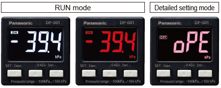
Two levels of configuration for easy operation of essential functions
The "RUN mode" is for setting the threshold value, the zero point adjustment and key lock/release setting, and the "detailed configuration" allows the basic settings of sensor operation. The two-level configuration enables an easy and immediate use of the product.
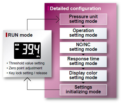
Main menu for detailed configuration
Operation setting mode*
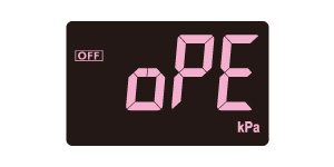
Select from EASY mode, hysteresis mode or window comparator mode.
NO / NC setting mode
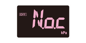
Set the comparative output operation to NO or NC.
Response time setting mode

Select the response time from 2.5 ms, 25 ms or 250 ms.
Display color setting mode
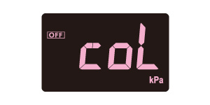
Select the comparative output ON / OFF display color and the normal display color from red or white.
Refer to Three output modes for details of operation setting mode.
Functional design
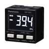
Black body for enhanced visibility of LCD display
The unit body is completely black to make the LCD display easier to see.
Firm and crisp clicking feel
The buttons offer firm and crisp clicking feel for smooth and reliable setting operations.

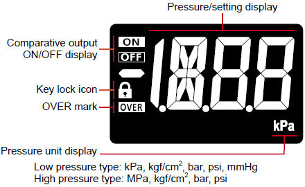
High-quality LCD display
Simple and highly visible display
The LCD offers a wide viewing angle so the display is easy to see even from an oblique angle. The
alphanumeric display (12-segment display), the key lock mark and the OVER mark are also clear and easy to see.
| Display color setting | RUN mode | Detailed setting mode | |
|---|---|---|---|
| Comparative output ON | Comparative output OFF | ||
| Red for ON, white for OFF | Red | White | Pink |
| White for ON, red for OFF | White | Red | |
| Red in normal status | Red | ||
| White in normal status | White | ||
Selection of display color from red or white
The display color can be selected from red or white in accordance with the output operation. Since the detailed setting mode display is pink (unchangeable), the pressure sensor status can be easily recognized by color.
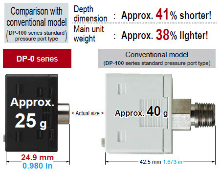
Compact & light weight design
Extra-short depth and light weight
The unit body measures only 24.9 mm 0.980 in in depth to allow installation in a narrow space. The main unit weighs only about 25 g. The lightweight unit means minimal load when mounted on a moving part such as a robot arm.
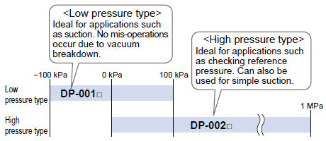
Low pressure type and high pressure type available
Two types to choose from depending on your application
The low pressure type can be used with positive or negative pressure, while the high pressure type is
suitable for positive pressure of up to 1 MPa.

Equipped with three output modes for use in a wide range of applications
(1)EASY mode
This mode is used for comparative output ON / OFF control.
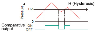
H: 4 digits (fixed) (10 digits or more when using psi unit)
(2)Hysteresis mode
This mode is used for setting comparative output hysteresis to the desired level and for carrying out ON / OFF control.
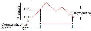
H: 2 digits or more (5 digits or more when using psi unit)
(3)Window comparator mode
This mode is used for setting comparative output ON and OFF at pressures within the setting range.
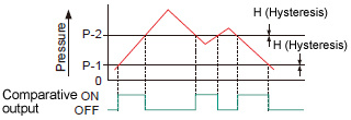
H: 4 digits or more (10 digits or more when using psi unit)

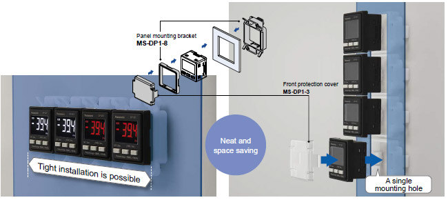
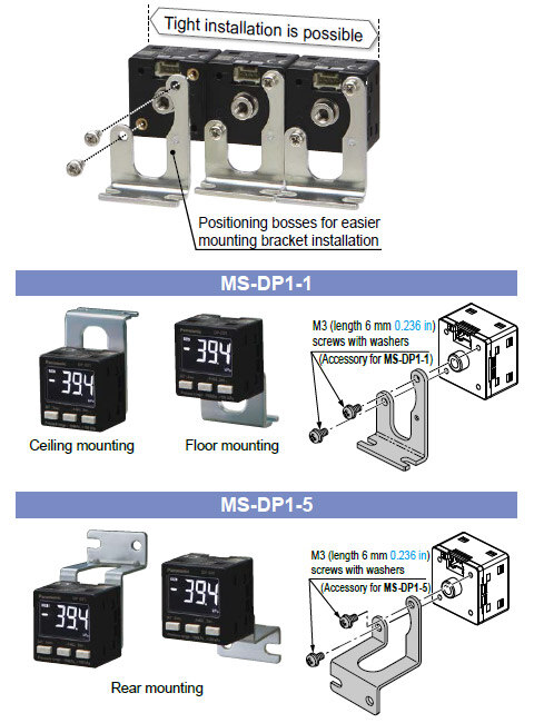
Panel mounting bracket
Tight installation is possible
An exclusive mounting bracket that is suitable for 1 to 3 mm 0.039 to 0.118 in panel thickness is available.
Exclusive mounting bracket
Supports tight installation
Space savings can also be achieved even when an L-shaped mounting bracket is used.
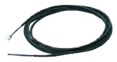
Connection cable
Cable can be connected with one-touch
Connector attached cable (2 m 6.562 ft), as an accessory, can be connected easily with one-touch connection.
* Options: 1 m3.281 ft/ 3 m9.843 ft/ 5 m16.404 fttypes are also available.
Types without connector attached cable are also available [DP-00□-J]
Commercially-available connectors can be used for cable connections. Cables in required length can be used, so this contributes to reduction in waste of unwanted cables.
![Types without connector attached cable are also available [DP-00□-J]](https://ap.industry.panasonic.com/hubfs/pid-corp/products/fasys/pressure/pressure/dp-0/images/pic18.jpg)
* Refer toOptionfor recommended commercially-available connectors.
------------------------------ Tab2 showing ------------------------------
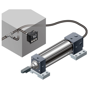
Applications
Suction confirmation for electronic parts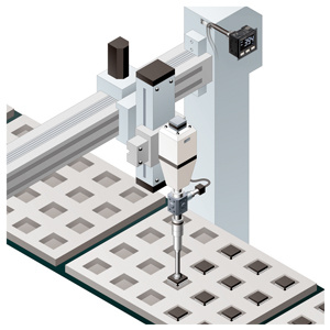
------------------------------ Tab3 showing ------------------------------
Order guide
Model No.
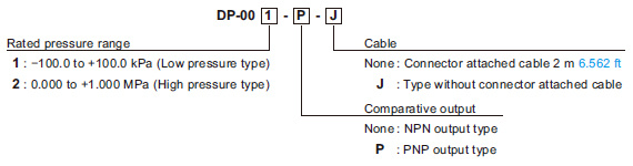
| Type | Appearance | Rated pressure range | Model No. | Pressure port | Comparative output |
|---|---|---|---|---|---|
| Low pressure type |
*CN-14A-C2 (Connector attached cable 2 m 6.562 ft) is attached. | -100.0 to +100.0kPa | DP-001 | M5 female thread | NPN open-collector transistor |
| DP-001-P | PNP open-collector transistor | ||||
| High pressure type | 0.000 to +1.000MPa | DP-002 | NPN open-collector transistor | ||
| DP-002-P | PNP open-collector transistor |
Type without connector attached cable
Type without connector attached cable CN-14A-C2 is available. When ordering this type, suffix "-J" to the end of Model No.
(e.g.) Type without connector attached cable of DP-001-P is "DP-001-P-J"
Accessory
•CN-14A-C2(Connector attached cable 2 m 6.562 ft)
------------------------------ Tab4 showing ------------------------------
Option
| Designation | Model No. | Description | |
|---|---|---|---|
| Connector attached cable | CN-14A-C1 | Length: 1 m 3.281 ft | 0.2 mm2 4-core cabtyre cable with connector on one end Cable outer diameter: ø3.7 mm ø0.146 in |
| CN-14A-C2 (Note) | Length: 2 m 6.562 ft | ||
| CN-14A-C3 | Length: 3 m 9.843 ft | ||
| CN-14A-C5 | Length: 5 m 16.404 ft | ||
| Connector attached cable (Flexible cable) | CN-14A-R-C1 | Length: 1 m 3.281 ft | 0.2 mm2 4-core flexible cabtyre cable with connector on one end Cable outer diameter: ø3.7 mm ø0.146 in |
| CN-14A-R-C2 | Length: 2 m 6.562 ft | ||
| CN-14A-R-C3 | Length: 3 m 9.843 ft | ||
| CN-14A-R-C5 | Length: 5 m 16.404 ft | ||
| Connector | CN-14A | Set of 10 housings and 40 contacts | |
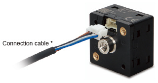
| Sensor mounting bracket | MS-DP1-1 | Allows sensors to be installed on the flooring or ceiling. Multiple sensors can also be mounted closely. | |
| MS-DP1-5 | Allows sensors to be installed on the wall. Multiple sensors can also be mounted closely. | ||
| Panel mounting bracket | MS-DP1-8 | Allows installation to panels with thickness of 1 to 3 mm 0.039 to 0.118 in. Multiple sensors can also be mounted closely. | |
| Front protection cover | MS-DP1-3 | Protects the adjustment surfaces of sensors. (Can be attached when using the panel mounting bracket) | |
| Conversion bushing | MS-DP1-7 | Pressure port can be converted to Rc1/8 female thread. | |
Note:The connector attached cable CN-14A-C2 is supplied with the DP-0 series. (Excluding DP-00□-J)
Connector attached cable
CN-14A-C□
CN-14A-R-C□
Sensor mounting bracket
MS-DP1-1
MS-DP1-5
Panel mounting bracket
Front protection cover
Recommended connector
Contact: SPHD-001T-P0.5,
Housing: PAP-04V-S
(Manufactured by J.S.T. Mfg. Co., Ltd.)
Note: Contact the manufacturer for details of the recommended products.
Recommended crimping tool
Model No.: YC-610R
(Manufactured by J.S.T. Mfg. Co., Ltd.)
Note: Contact the manufacturer for details of the recommended products.
Recommended e-CON connector
Manufactured by 3M Japan Limited
Adapted connector : 37104-3122-000 FL
Please refer to "Introducing the 3M™ mini-clamp connector" for details.


------------------------------ Tab5 showing ------------------------------
------------------------------ Tab6 showing ------------------------------
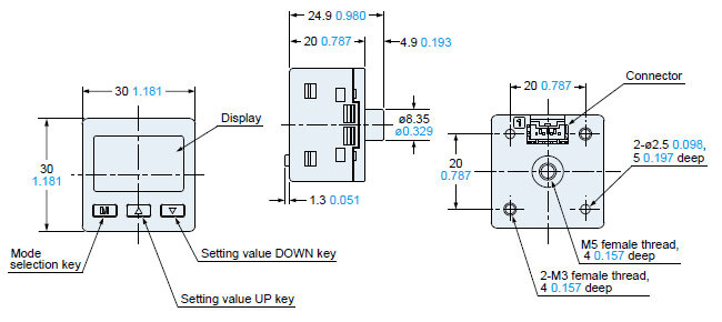
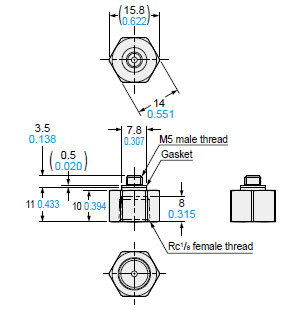
Dimensions
- Unit: mm in
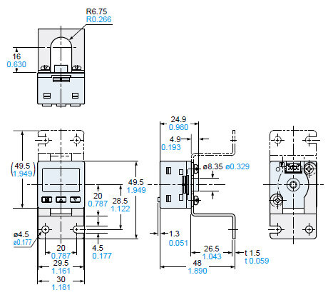
DP-00□
Sensor
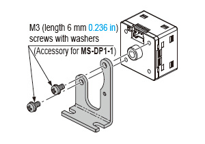
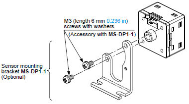
MS-DP1-1
Sensor mounting bracket (Optional)
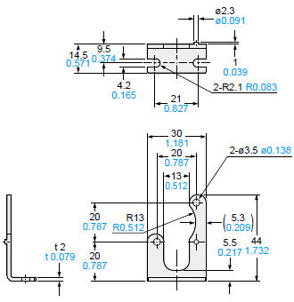
Material: Cold rolled carbon steel (SPCC) (Uni-chrome plated)Two M3 (length 6 mm0.236 in) screws with washers are attached.
Assembly dimensions
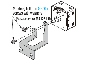
MS-DP1-5
Sensor mounting bracket (Optional)
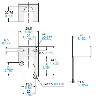
Material: Stainless steel (SUS304)Two M3 (length 6 mm0.236 in) screws with washers are attached.
Assembly dimensions
MS-DP1-7
Material: Brass (Nickel plated)Weight: 10 g approx.
Assembly dimensions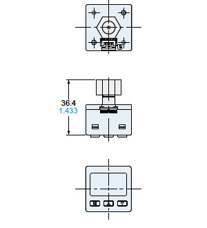
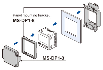
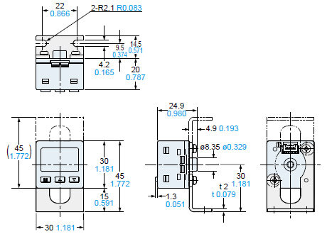
MS-DP1-8
MS-DP1-3
Panel mounting bracket (Optional), Front protection cover (Optional)
Mounting drawing with DP-00□
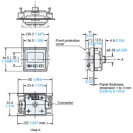
Material: Polyacetal (Panel mounting bracket), Polycarbonate (Front protection cover)
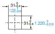
Panel cut-out dimensions
When 1 unit is installed
When "n" units are installed horizontally in series
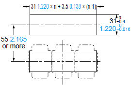
Note: The panel thickness should be 1 to 3 mm0.039 to 0.118 in.
When "n" units are installed vertically in series
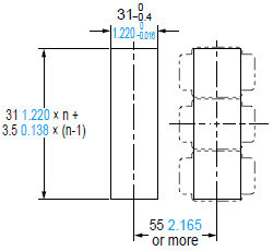
Note: The panel thickness should be 1 to 3 mm0.039 to 0.118 in.
CN-14A(-R)-C□
Connector attached cable (Optional, CN-14A-C2 is attached to the sensor)
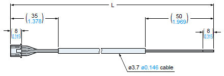
| Model No. | Cable length L (mm in) |
|---|---|
| CN-14A(-R)-C1 | 1,000 39.370 |
| CN-14A(-R)-C2 | 2,000 78.740 |
| CN-14A(-R)-C3 | 3,000 118.110 |
| CN-14A(-R)-C5 | 5,000 196.850 |
------------------------------ Tab7 showing ------------------------------
I/O Circuit and Wiring diagrams
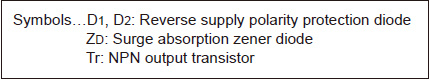
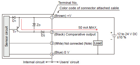
NPN output type
I/O circuit diagram
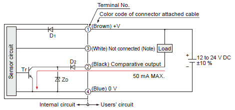
Note: Open or, connect to 0 V.
Terminal arrangement diagram
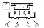
| Terminal No. | Designation |
|---|---|
| ① | +V |
| ② | Comparative output |
| ③ | Not connected (Note) |
| ④ | 0V |
Note: Open or, connect to 0 V.
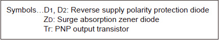
PNP output type
I/O circuit diagram
Note: Open or, connect to 0 V.
Terminal arrangement

| Terminal No. | Designation |
|---|---|
| ① | +V |
| ② | Comparative output |
| ③ | Not connected (Note) |
| ④ | 0V |
Note: Open or, connect to 0 V.
------------------------------ Tab8 showing ------------------------------
Part description
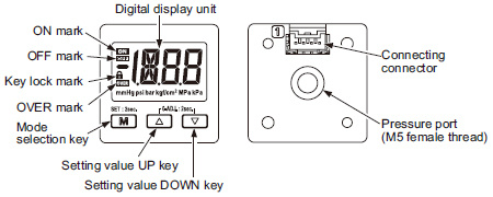
Piping
- When using this product, connect a joint available in the market to the pressure port. At the time, the tightening torque should be 1.0 N·m or less.
Mounting
- Use sensor mounting bracket MS‑DP1‑1 prepared independently. When mounting this product with sensor mounting bracket, etc., the tightening torque should be 0.5 N·m or less.
- Panel mounting bracket MS‑DP1‑8 (optional) and front protection cover MS‑DP1‑3 (optional) are available.
- For the method for mounting panel mounting bracket, refer to the instruction manual that came with the MS‑DP1‑8.
Wiring
- Make sure that the power supply is OFF while performing the wiring operation.
- Verify that the supply voltage variation is within the rating.
- If power is supplied from a commercial switching regulator, ensure that the frame ground (F.G.) terminal of the power supply is connected to an actual ground.
- In case noise generating equipment (switching regulator, inverter motor, etc.) is used in the vicinity of this product, connect the frame ground (F.G.) terminal of the equipment to an actual ground.
- When extending the cable, use a cable whose conductor crosssection area is 0.3 mm2 or more. The cable can be extended to up to 10 m 32.808 ft in total length.
- Do not run the wires together with high-voltage lines or power lines or put them in the same raceway. This can cause malfunction due to induction.
- Do not apply stress directly to the connection cable leader or to the connector.
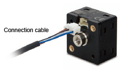
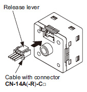
Connection
How to connect
- Insert the cable with connector CN‑14A(‑R)‑C□ into this product's connection connector section as shown in the right figure.
How to disconnect
- Pressing the release lever of the cable with connector, pull out the connector.
Note:Do not pull by holding the cable without pressing the release lever, as this can cause cable break or connector break.
Factory setting
| Type | Low pressure type | High pressure type |
|---|---|---|
| Operation setting | EASY mode | |
| NO / NC setting | NC | NO |
| Threshold value | -50.0 | 0.500 |
| Pressure unit | kPa | MPa |
| Display color | Red when ON, White when OFF | |
| Response speed | 2.5ms | |
Error indication
| Error indication | Description | Remedy |
|---|---|---|
 | The load is short-circuited causing an overcurrent to flow. | Turn OFF the power and check the load. |
 | Pressure is applied during zero point adjustment. | Applied pressure at the pressure port should be brought to atmospheric pressure and zero-point adjustment should be done again. |
 | The applied pressure exceeds the upper limit of the displayed pressure range. | Applied pressure range should be brought within the rated pressure range. |
 | The applied pressure exceeds the lower limit (back pressure) of the displayed pressure range. |
When other error massage is displayed, contact us.
Others
- This product has been developed / produced for industrial use only.
- The product shall be used only within the rated pressure range.
- Do not apply pressure exceeding the pressure resistance.
Otherwise, destruction of diaphragm occurs, preventing the product to perform normal operation. - Do not use during the initial transient time (0.5 sec.) after the power supply is switched ON.
- The specification may not be satisfied in a strong magnetic field.
- This product is suitable for indoor use only.
- Take care that strong impact such as fall is not given to this product. Otherwise, it may be destroyed.
- Avoid dust, dirt, and steam.
- Take care that the product does not come into contact with organic solvents such as thinner.
- Take care that the product does not come into contact with oil or grease.
- Take care that the product does not come into contact with strong acid or alkaline.
- Do not insert wire into the pressure port. Otherwise, destruction of diaphragm occurs, preventing the product to perform normal operation.