Discontinued Products

Dimensions
- Unit: mm in
LD-600 LD-601
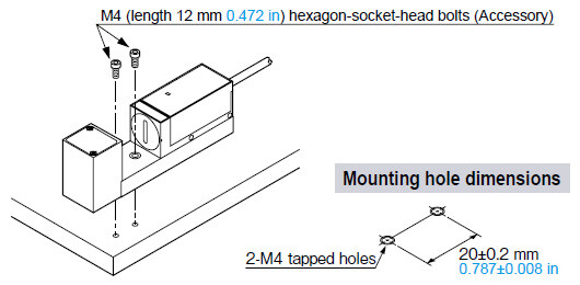
Sensor head
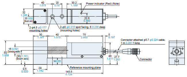
Two M4 (length 12 mm0.472 in) hexagon-socket-head bolts are attached.Note: In LD-601, this is the laser emission indicator (green).Note:In LD-601, this is the laser emission indicator (green).
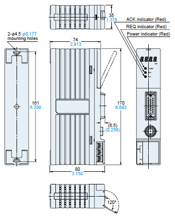
LD-C60
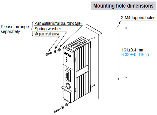
Controller
MS-DIN-IDC
DIN rail adapter (Optional)
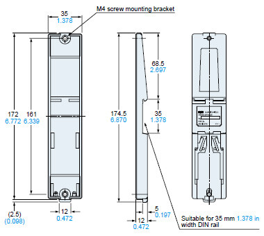
Two M4 (length 12 mm 0.472 in) screws with washers are attached.
I/O Circuit and Wiring diagrams
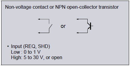
I/O circuit diagram
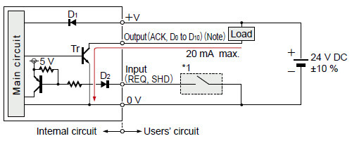

Note: Insulate all unused wires individually to avoid miscontact.
*1
I/O Terminal Arrangement
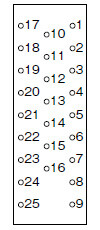
Attached connector
Solder side
| Pin No. | Symbol | I/O | Description |
|---|---|---|---|
| 1 | REQ | Input | Data output request |
| 2 | ACK | Output | Data being output |
| 3 | SHD | Input | Shading correction |
| 4 | - | - | Not connected |
| 5 | - | - | Not connected |
| 6 | - | - | Not connected |
| 7 | - | - | Not connected |
| 8 | G | - | 0 V |
| 9 | G | - | 0 V |
| 10 | D0 | Output | Data (20) |
| 11 | D1 | Output | Data (21) |
| 12 | D2 | Output | Data (22) |
| 13 | D3 | Output | Data (23) |
| 14 | D4 | Output | Data (24) |
| 15 | D5 | Output | Data (25) |
| 16 | D6 | Output | Data (26) |
| 17 | D7 | Output | Data (27) |
| 18 | D8 | Output | Data (28) |
| 19 | D9 | Output | Data (29) |
| 20 | D10 | Output | Data (210) |
| 21 | - | - | Not connected |
| 22 | - | - | Not connected |
| 23 | - | - | Not connected |
| 24 | G | - | 0 V |
| 25 | G | - | 0 V |
- This product is classified as a Class 1 Laser Product in IEC / JIS standards and a Class II Laser Product in FDA regulations 21 CFR 1040.10. Do not look at the laser beam though optical system such as a lens.
- The following label is attached to the product. Handle the product according to the instruction given on the warning label.
 | (The English warning label based on FDA regulations is pasted on the FDA regulations conforming type.) |
- This product has been designed to meet the specifications when it is used along with the optional exclusive controller. If a controller other than the exclusive controller is used, not only the specifications may not be met, but it may also be a cause for malfunction or break down. Hence, please ensure to use this product along with the optional exclusive controller.
- Before using this product, please allow a warming up time of 3 min. approx. after the power supply is switched on.
- Never disassemble the sensor head.
Safety standards for laser beam products
Classification by IEC 60825-1
| Classification | Description |
|---|---|
| Class 1 | Lasers that are safe under reasonably foreseeable conditions of operation, including the use of optical instruments for intrabeam viewing. |
Note: LD-601 conforms to FDA Class II.
- A laser beam can harm human being's eyes, skin, etc., because of its high energy density. IEC has classified laser products according to the degree of hazard and the stipulated safety requirements.
The LD series is classified as Class 1 laser.
Safe use of laser products
- For the purpose of preventing users from suffering injuries by laser products, IEC 60825-1 (Safety of laser products).
Please check the standards before use.
Conditions in use for CE conformity
- The LD series is CE compliant and complies with EMC directives. EN 61000-6-2 is the applicable standard that covers immunities relating to use of this product, but in order to comply with this standard, the following conditions must be satisfied.
Conditions
- This controller should be connected less than 10 m 32.808 ft from the power supply.
- The signal line to connect with this controller should be less than 30 m 98.425 ft.
Mounting
- Mount the sensor head using the attached 2 pcs. M4 (length 12 mm 0.472 in) hexagon-socket-head bolts, with a tightening torque of 1.2 N・m or less.
- Mount the controller using 2 pcs. M4 pan head screws, with a tightening torque of 1.2 N・m or less.
Wiring
- Make sure that the power supply is off while wiring.
- Verify that the supply voltage variation is within the rating.
- Make sure to use an isolation transformer for the power supply. It an auto-transformer (single winding transformer) is used, this product or the power supply may get damaged.
- In this sensor head, capacitor earth is used to enhance the noise characteristics. In case there is a high frequency noise generating equipment, such as, an ultrasonic welding machine, etc., near the sensor head and if the mounting base is electrically conducting (metallic, etc.), then insulate the sensor head from the mounting base.
- In case noise generating equipment (switching regulator, inverter motor, etc.) is used in the vicinity of the sensor head or the controller, connect the frame ground (F.G.) terminal of the equipment to an actual ground.
- In case a surge is generated in the used power supply, connect a surge absorber to the supply and absorb the surge.
- Do not run the wires together with high-voltage lines or power lines or put them in the same raceway. This can cause malfunction due to induction.
- In order to reduce noise, make the wiring as short as possible.
Others
- This product is not a measuring instrument. Hence, the company does not offer any calibration services.
- Do not allow any water, oil, fingerprints, etc., which may refract light, or dust, dirt, etc., which may block light, to stick to the emitting / receiving surfaces of the sensor head. In case they are present, wipe them with a clean, soft cloth or lens paper.
- Avoid dust, dirt, and steam.
- Take care that the sensor head and the controller does not come in direct contact with water, oil, grease, or organic solvents, such as, thinner, etc.
- Take care that the sensor head and the controller are not directly exposed to fluorescent light from a rapid-starter lamp or a high frequency lighting device, as it may affect the sensing performance.