Specifications
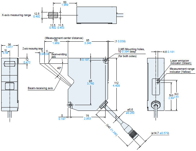
Sensor heads
| Type | Diffuse reflection type |
|---|
| Model No. | HL-D301B | HL-D301C |
|---|
| CE marking directive compliance | EMC Directive, RoHS Directive |
|---|
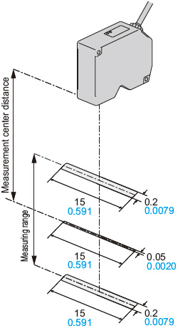
| Measurement center distance | 50 mm 1.969 in |
|---|
| Height (Z axis) measurement range | ±10 mm ±0.394 in |
|---|
Measurement
range of width
(X axis) | Near side | 11.5 mm 0.453 in |
|---|
| Measurement center | 12.5 mm 0.492 in |
|---|
| Far side | 12.5 mm 0.492 in |
|---|
Unit of measurement
output | Height (Z axis) | 0.1 μm 0.004 mil |
|---|
| Width (X axis) | 1 μm 0.039 mil (Note 2) |
|---|
| Resolution | Height (Z axis) | 1 μm 0.039 mil (Note 3) |
|---|
| Width(X axis) | 5 μm 0.197 mil (Note 2, 4) |
|---|
| Linearity (Note 5) | Height (Z axis) | ±0.1 % F.S. |
|---|
| Temperature characteristic | 0.02 % F.S./℃ |
|---|
| Light source | Red semiconductor lase (Peak wavelength 658 nm 0.026 mil) |
|---|
| | Output | Max. output: 1 mW | Max. output: 5 mW |
|---|
| Laser class | Class 2
[IEC / JIS / FDA (Note 6)] | Class 3R
[IEC / JIS / FDA (Note 6)] |
|---|
| Beam size (Note 7) | 50 μm × 15 mm 1.969 mil × 0.591 in |
|---|
| Receiving element | CMOS 2D image sensor |
|---|
| Indicator | Laser emission | Green LED (lights up during laser emission) |
|---|
| Measurement range | Yellow LED
[lights up when near the measurement center distance, blinks when within the measuring range,
and lights out when outside of the measuring range. (at the measurement center position in the width direction)] |
|---|
Environmental
resistance | Protection | IP67 (IEC) (excluding the connector) |
|---|
| Ambient temperature | 0 to +45 ℃ +32 to +113 ℉ (No dew condensation allowed),
Storage: -20 to +70 ℃ -4 to +158 ℉ |
|---|
| Ambient humidity | 35 % to 85 % RH, Storage: 35 % to 85 % RH |
|---|
| Ambient illuminance | Incandescent light: 3,000 ℓx or less at the light-receiving face
(No direct sunlight or its reflection allowed) |
|---|
| Vibration resistance | 10 to 55 Hz (period: 1 min.) frequency, 1.5 mm 0.059 in double amplitude in X,Y and Z directions for two hours each |
|---|
| Shock resistance | 196 m/s2 acceleration (20 G approx.) in X,Y and Z directions three times each |
|---|
| Cable | Cabtyre cable, 0.5 m 1.640 ft long with connector |
|---|
| Cable extension | Extension up to total 20 m 65.617 ft is possible, with optional cable. |
|---|
| Materials | Enclosure: Die-cast aluminum, Case cover: Die-cast aluminum, Front cover: Glass |
|---|
| Weight | 500 g approx. (including cable) |
|---|
| Accessory | Laser warning label: 1 set |
|---|
Notes:
1) Where measurement conditions have not been specified precisely, the conditions used were as follows: (connected to the controller) supply voltage 24 V DC, ambient temperature +20 ℃ +68 ℉, MZBC mode (adjustment unit: width of 100 μm 3.937 mil), unit light receiving time 100 μs, average number of samples 64, measurement center distance, and target object is a white, light-diffusing object.
2) It is a value in which the sensor heads connected to a controller Ver. 2.00 or higher.
3) The value is the average of height measurement in full width at the measurement center distance.
4) This is the measurement value of a pin gauge rounded surface in the edge position measurement (start of falling edge) calculation setting. The measurement object: white ceramic pin gauge (ø10 mm ø0.394 in), unit light receiving time: 200 μs, measurement value extraction: base light intensity control, average number of samples: 64, width smoothing: ±4, all others are the initial settings.
5) Value represents the error in comparison with the ideal line of height measuring range (full scale) for the height measurement of the measurement center position in the width direction. The value in the specifications is the value within ±7.5 mm ±0.295 in of the height measuring range.
6) This product complies with 21 CFR 1040.10 and 1040.11 Laser Notice No. 50, dated June 24, 2007, issued by CDRH (Center for Devices and Radiological Health) under the FDA (Food and Drug Administration).
7) This size applies when using measurement center distance and is defined as 1/e2 (13.5 % approx.) of the center light intensity. Leaked light occurs outside of the defined range; sensing performance may be affected when the reflectance around the detection point is higher than that detection point.
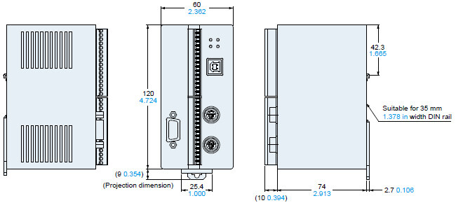
Controller
| Model No. | HL-D3C |
|---|
| Applicable sensor heads | HL-D301B, HL-D301C |
|---|
| Connectable sensor heads | Number of connectable units: Max. 2 units |
|---|
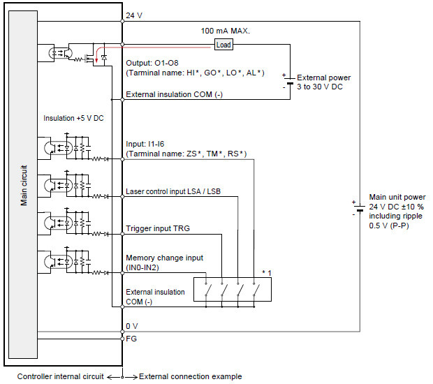
| Supply voltage | 24 V DC ±10 % including ripple 0.5 V (P-P) |
|---|
| Current consumption | 1 A or less (when 2 sensor heads are connected) |
|---|
| Sampling rate | Depends on the sensing mode and settings
Multi-zone beam control mode : Standard 12.2 ms (Note 2)
Whole synchronized measurement mode : Max. 2.5 ms (Note 3)
Multi-select displacement sensing mode : Max. 80 μs (Note 4) |
|---|
| Judgment output | N-channel FET, open drain
• Maximum sink current: 100 mA
• Applied voltage: 30 V DC or less (between output terminal and 0 V)
• ON-resistance: 5 Ω or less |
|---|
| | Output operation | Open during output operation (switchable) |
|---|
| Short-circuit protection | Incorporated |
|---|
| Alarm output | N-channel FET, open drain
• Maximum sink current: 100 mA
• Applied voltage: 30 V DC or less (between output terminal and 0 V)
• ON-resistance: 5 Ω or less |
|---|
| | Output operation | Open when alarm is triggered (switchable) |
|---|
| Short-circuit protection | Incorporated |
|---|
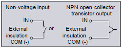
| External trigger input | Photocoupler insulation input |
|---|
| | Input operation | ON: short-circuiting to external insulation COM (-) , OFF: when open |
|---|
| Applied voltage | 30 V DC or less (leakage current: 0.1 mA or less) |
|---|
| Laser control input | Photocoupler insulation input |
|---|
| | Input operation | Laser emission: short-circuiting to external insulation COM (-) , Laser emission OFF: when open |
|---|
| Applied voltage | 30 V DC or less (leakage current: 0.1 mA or less) |
|---|
| Zero set input | Photocoupler insulation input |
|---|
| | Input operation | ON: short-circuiting to external insulation COM (-) , OFF: when open |
|---|
| Applied voltage | 30 V DC or less (leakage current: 0.1 mA or less) |
|---|
| Timing input | Photocoupler insulation input |
|---|
| | Input operation | ON: short-circuiting to external insulation COM (-) , OFF: when open |
|---|
| Applied voltage | 30 V DC or less (leakage current: 0.1 mA or less) |
|---|
| Reset input | Photocoupler insulation input |
|---|
| | Input operation | ON: short-circuiting to external insulation COM (-) , OFF: when open |
|---|
| Applied voltage | 30 V DC or less (leakage current: 0.1 mA or less) |
|---|
| RS-232C interface | Baud rate: 9,600, 19,200, 38,400, 57,600, 115,200 bit/s(Note 5) |
|---|
| USB interface | USB 2.0 full-speed (USB 1.1 compatible) |
|---|
| Settings / Data display | HL-D3SMI (accessory) or dedicated API |
|---|
| Indicator | Power | Green LED
(lights up at power on) |
|---|
Sensor head A
Laser radiation | Green LED
[During continuous sensing: lights up during laser emission, blinks twice when turning off
During sensing stop process: alternately lights up during laser emission (ON: 1 sec / OFF: 1 sec),
blinks once when turning off] |
|---|
Sensor head B
Laser radiation | Green LED
[During continuous sensing: lights up during laser emission, blinks twice when turning off
During sensing stop process: alternately lights up during laser emission (ON: 1 sec / OFF: 1 sec),
blinks once when turning off] |
|---|
| Alarm | Red LED
(lights up when there is a sensing alarm or sensor head wire breakage) |
|---|
Environmental
resistance | Ambient temperature | 0 to +50 ℃ +32 to +122 ℉ (No dew condensation or icing allowed), Storage: -20 to +70 ℃ -4 to +158 ℉ |
|---|
| Ambient humidity | 35 to 85 % RH , Storage: 35 to 85 % RH |
|---|
| Vibration resistance | 10 to 55 Hz frequency (period: 1 min) , 0.75 mm 0.030 in double amplitude in X, Y, and Z directions for 30 min. each |
|---|
| Shock resistance | 196 m/s2 acceleration (20G approx.) in X, Y, and Z directions three times each |
|---|
| Material | Enclosure: Aluminum |
|---|
| Weight | 300 g approx. |
|---|
| Accessories | HL-D3 set-up CD-ROM, (including HL-D3SMI and User's Manual), Instruction manual, USB cable (2 m 6.562 ft) |
|---|
Notes:
1) Where measurement conditions have not been specified precisely, the conditions used were as follows: (connected to the sensor head) supply voltage 24 V DC, ambient temperature +20 ℃ +68 ℉, MZBC mode (adjustment unit: width of 100 μm 3.937 mil), unit light receiving time 100 μs, average number of samples 64, measurement center distance, and target object is a white, light-diffusing object.
2) Value for using two judgment outputs with 1 sensor head in MZBC mode, with each measuring range set to Max. and light intensity not adjusted (continuous sensing).
3) Value for obtaining displacement shape waveform data using buffering and 2 sensor heads in whole synchronized measurement mode, with each measuring range set to Min. (no OUT calculation).
4) Value for using 2 judgment outputs with 1 sensor head in MSDS mode, with the unit light receiving time set to 40 μs, light intensity not adjusted (continuous), and 2 points selected (without wide cell function).
5) Products produced from September 2013 (Ver. 2) are also compatible with 9,600, 19,200 and 38,400 bit/s.