Basic Information

Robust and slim body contributes to a longer service life
The optical absolute method eliminates “value skipping” and “unset zero point”!


-
Communication Unit for Digital Displacement sensor SC-HG1
Please check "Communication Unit for Digital Displacement sensor SC-HG1" which can connect digital displacement sensor controller as well.
>>Communication Unit for Digital Displacement sensor SC-HG1
Features
Sensor that diagnoses its own state. Featuring a self-monitoring function!
Self-monitoring function released by using the digital displacement sensor communication unit SC-HG1 in combination with digital displacement sensor HG-S series and HG-T series.
>>HG-S / HG-T self-monitoring function
>>Communication Unit for Digital Displacement Sensors SC-HG1
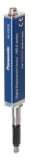
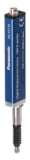
SENSOR HEAD
Slim & light body
Box type with an ultra-slim 11 mm 0.433 in width. Furthermore, the unit weighs only approx. 80 g. (Note 1)
Note 1: Values on the 10 mm 0.394 in type (HG-S1010□ / HG-S1110□)
Plain bearings with 2-point support structure
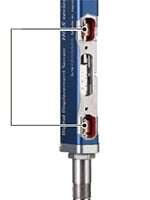
A new structure supports the spindle with upper and lower plain bearings to significantly increase rigidity. Unlike ball bearings, these bearings efficiently disperse lateral loads on the spindle, significantly reducing the risk of breakage.
Bending-resistant cable
A bending-resistant cable provides peace of mind even when the sensor is installed on a movable tool.
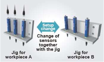
Hot-swappable
Change of sensor head without turning off the power supply
The sensor head can be changed safely without turning off the controller. This reduces the man-hours required for the change of line setup for processing of different workpieces, thus achieving a significant reduction of setup change time.
Metal guide whirl-stop structure
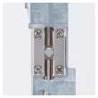
Spindle whirl-stop is accomplished by means of a metal guide requiring a several μm level assembly precision. Unlike a plastic guide, the risk of measurement error and glass scale breakage caused by deformation, wear, and other deterioration is significantly reduced.
No “value skipping” or “unset zero point”
Displacement is measured by reading a glass scale with a different slit pattern at each reading position using a highresolution sensor. This eliminates "value skipping" even when measuring at high speed, and there is no concern of "unset zero point".
Tip deviation amount of 35 μm 1.378 mil or less (typical value) (Note 2)
(Note 2) :
Value calculated from the clearance of the upper and lower plain bearings.
[40 μm 1.574 mil or less (typical value) on the HG-S1032 / HG-S1050 (Note 2)]
Tip deviation that reduces measurement precision is also minimized. Deviation of the measurement point is held to a minimum.
Class-top resolution
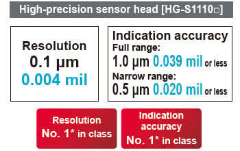
* As of October 2023, in-company survey.
Resistance to shock and vibration
| 10 mm 0.394 in type | 32 mm 1.260 in type | 50 mm 1.969 in type | |
|---|---|---|---|
| Shock resistance | 1,960 m/s2 acceleration in X, Y and Z directions three times each | 1,960 m/s2 acceleration in X, Y and Z directions three times each | 980 m/s2 acceleration in X, Y and Z directions three times each |
| Vibration resistance | 10 to 500 Hz frequency, 3 mm 0.118 in double amplitude (10 to 58 Hz), Maximum acceleration 196 m/s2 (58 to 500 Hz) in X, Y and Z directions for two hours each | 10 to 150 Hz frequency, 3 mm 0.118 in double amplitude (10 to 58 Hz), Maximum acceleration 196 m/s2 (58 to 150 Hz) in X, Y and Z directions for two hours each | 10 to 55 Hz frequency, 1.5 mm 0.059 in double amplitude in X, Y and Z directions for two hours each |

* In the case of the 10 mm 0.394 in type / 32 mm 1.260 in type
As of October 2023, in-company survey.
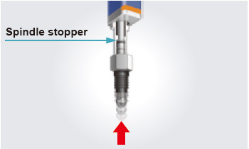
[Resistant to upward thrust impact]
Spindle stopper installed
Even if unexpected upward thrust occurs, the lower turning off the power supply part of the spindle blocks the impact. Damage to the internal structure, including the glass scale, is minimized.
Regular type
Impressive durability
Resistance to lateral load
Original test was conducted to ensure durability against vertical sliding and lateral load that sensors are often subjected to in actual operations. There is a reason why you can use this product with peace of mind for a long time.
■Durability to withstand more than 200 million vertical sliding operations (typical value) (Note 3)
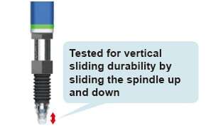
Note 3: Value on the HG-S1010 / HG‑S1110.
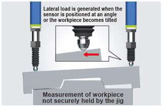
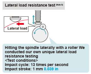
■Withstands more than 100 million sliding operations under application of lateral load (typical value) (Note 4)
Example of a lateral load occurring in the workplace
(Note 4) :
Value on the HG-S1010 / HG-S1110.
(Note 5) :
Button-type probe for evaluation purposes was installed on the test sample for the lateral load resistance test.
* In the case of the HG-S1010 / HG-S1110 As of October 2023, in-company survey.
Air-driven type
Air-driven type sensor heads simplify equipment mechanisms.
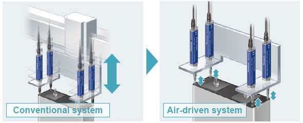
There is no need to design a mechanism for moving the sensor head. This eliminates the design cost and manhours and improves equipment accuracy.Reduces installation spaces
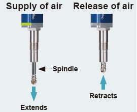
Supply and release of air moves the spindle up and down.
Eliminates the need for designing and installing a mechanism to move the sensor head up and down.
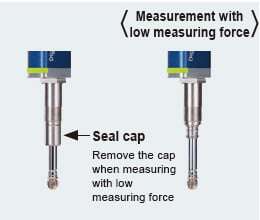
Compatible with low measuring force
Removal of the seal cap from the main unit allows measurement with low measuring force. The low probe contact force minimizes the possibility of workpiece damage.
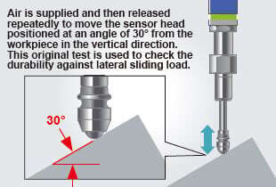
High durability against lateral sliding load
Number of lateral sliding cycles: 10,000,000 or more (typical value) (under continuous testing) The robust sensor head helps reduce damage caused by workpiece setup mistakes.
■Our original durability test against lateral sliding load
CONTROLLER
Versatile and Easy-to-Use Controller
The controller features the industry's first* dual display and offers versatile functions and excellent ease of use. It allows simple and reliable operation of the advanced measurement function in a diversity of applications.
* As a sensor product using optical absolute method, as of September 2015 (according to in-company survey)
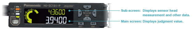
Dual display for added indication flexibility (equipped with NAVI function)
The 2-line digital display simultaneously shows head measurement (measured value) and judgment value (calculated value).
All-direction LCD
The high-contrast LCD provides sharp and clear indications and wide viewing angle.
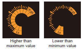
Equipped with intuitive circle meter
Values between allowable maximum and minimum values are indicated in green. Values outside of the allowable range are indicated in orange. This provides at-a-glance understanding of the margin to the tolerance limits.
Anytime selection of function to copy
The selective copy function significantly reduces the man-hours required for initial setting and maintenance.

High-speed response of 3 ms in combination with any sensor head
Provided with maintenance mode useful on production floor
The following data is saved in the memory. The stored data can be used effectively for on-site analysis.
• Maximum peak value during operation
• Number of times maximum stroke was exceeded
• Cumulative spindle moving distance (m)
Alarm setting for notification of upward thrust
Alarm can be set to notify the user when upward thrust (stroke) exceeds the value set by the user.
Easy-to-understand 2-line digital display
The 2-line digital display simultaneously shows sensor head measurement and judgment value.
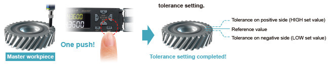
Easy tolerance setting
Simple 1-point teaching
Align with master workpiece and press ENTER key for easy tolerance setting.
No need for trigger input
Equipped with self-trigger hold function
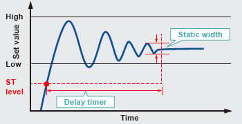
Easy setting of time length from measurement start to measurement stabilization. Minimizes measurement fluctuation due to the vibration caused by stopping of spindle rotation.
(1) Static width setting
Stability range above the ST level can be set as desired.
Set the range where measurements are considered to be stable.
(2) Delay timer setting
Desired delay time after measurement exceeding the ST level can be set.
Set the time required for stabilization of measurement.
Lateral connection of slave units for added operational ease
Connection of up to 15 slaves units
One master unit can be connected with up to 15 slave units in any order. This allows easy multi-point calculations.
* When a digital displacement sensor communication unit is connected, a maximum of 14 slave units can be connected per master unit.
Controller variations
■Master unit (1 model)
・High performance type (analog current + input / output)
■Slave unit (3 models)
・High performance type (analog current + input / output)
・Standard type (input / output)
・Wire-saving type
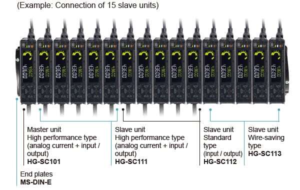
* End plates (optional) must be mounted on both sides of the controller after the connection of slave units.


Order guide
Sensor heads (Air-Driven Type)
| Type | Appearance | Resolution | Measurement range | Model No. | |
|---|---|---|---|---|---|
| 10 mm 0.394 in type (Note 1) | General purpose |
| 0.5μm 0.02 mil | 10mm 0.394 in (Note 2) | HG-S1010-AC |
| High precision |
| 0.1μm 0.004 mil | HG-S1110-AC | ||
Notes :
1) Be sure to use the sensor in combination with an HG-SC□ controller manufactured in or after February 2019.
2) The position that represents "0" as an absolute value is a position where the spindle is pushed further down from the bottom dead point by 0.1 mm 0.004 in or more.
Sensor heads (Regular Type)
| Type | Appearance (Note 1) | Resolution | Measurement range | Model No. | ||
|---|---|---|---|---|---|---|
| 10 mm 0.394 in type | General purpose | Standard |
| 0.5μm 0.02 mil | 10mm 0.394 in | HG-S1010 |
| Low measuring force (Note 2) | HG-S1010R | |||||
| High precision | Standard |
| 0.1μm 0.004 mil | HG-S1110 | ||
| Low measuring force (Note 2) | HG-S1110R | |||||
| 32 mm 1.260 in type | General purpose | Standard |
| 0.5μm 0.02 mil | 32mm 1.260 in | HG-S1032 |
| 50 mm 1.969 in type | General purpose | Standard |
| 0.5μm 0.02 mil | 50mm 1.969 in | HG-S1050 (Note 3) |

Notes:
1) The image shows the standard type only.
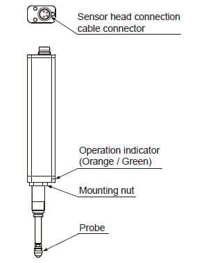
2) The low measuring force type does not have a rubber bellows.
3) Always connect the 50 mm 1.969 in type (HG-S1050) to an HG-SC□ controller manufactured February 2019 or later.
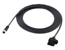
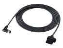
Sensor head connection cables (bending-resistant type)
| Designation | Appearance | Length | Model No. |
|---|---|---|---|
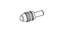
| Straight connector |
| 3 m 9.843 ft | CN-HS-C3 |
| 7 m 22.966 ft | CN-HS-C7 | ||
| 10 m 32.808 ft | CN-HS-C10 | ||
| 20 m 65.617 ft | CN-HS-C20 | ||
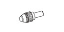
| L-shaped connector (Note 1) |
| 3 m 9.843 ft | CN-HS-C3L |
| 7 m 22.966 ft | CN-HS-C7L | ||
| 10 m 32.808 ft | CN-HS-C10L | ||
| 20 m 65.617 ft | CN-HS-C20L |
Note 1: Not compatible with air-driven type sensor heads (HG-S1010-AC / HG-S1110-AC).
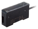
Controllers
Up to 15 slave units can be connected per master unit.
| Type | Appearance | Output | Number of connectable controllers | Model No. | |
|---|---|---|---|---|---|
| Master unit | High performance type (analog current + input / output) |
| NPN output | Up to 15 slave units can be connected per master unit. (Note) | HG-SC101 |
| PNP output | HG-SC101-P | ||||
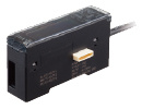
| Slave units | High performance type (analog current + input / output) |
| NPN output | HG-SC111 | |
| PNP output | HG-SC111-P | ||||
| Standard type (input / output) | NPN output | HG-SC112 | |||
| PNP output | HG-SC112-P | ||||
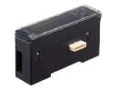
| Wire-saving type |
| - | HG-SC113 | ||
Note: When connected to a communication unit for digital displacement sensor, up to 14 slave units can be connected per master unit
Communication units for digital displacement sensors
- For further information about communication units for digital displacement sensors, please refer to"the Order guide page of SC-HG1, communication units for digital displacement sensors."
End plates
End plates are required for connection of controllers.
MS-DIN-E
[2 pcs. per set]
Option
| Designation | Appearance | Model No. | Description |
|---|---|---|---|
| Probe |
| HG-SS10Cx5 [5 pcs. per set] | Standard type |
| HG-SS10H | Super-hard type | |
| HG-SS20H | Super-hard needle type | |
| HG-SS30S | Flat-seated type | |
| HG-SS40U | Roller type(Note 1) | |
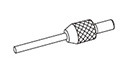
| Joint (Note 1)(Note 2) |
| HG-SJ15 | Length 15 mm 0.591 in type |
| HG-SJ25 | Length 25 mm 0.984 in type | |
| Rubber bellows |
| HG-SGN10x5 [5 pcs. per set] | For 10 mm 0.394 in type sensor head |
| HG-SGN32x5 [5 pcs. per set] | For 32 mm 1.260 in type sensor head | |
| HG-SGN50x5 [5 pcs. per set] | For 50 mm 1.969 in type sensor head | |
| Seal cap |
| HG-SASCx5 [5 pcs. per set] | This seal cap is for air-driven 10 mm 0.394 in type sensor head. As part of preventive maintenance, replace the seal cap before the internal O-ring wears out. Replace the seal cap at an appropriate time (after about 5 million sliding operations) according to the degradation condition of the installed seal material. |
Notes :
1) The joint (optional) cannot be used if a low-measuring-force type sensor head (HG-S1010R, HG-S1110R) is installed laterally and the HG-SS40U roller-type probe (optional) is used.
2) Only one joint (optional) can be installed to one sensor head.
Specifications
Sensor heads
Air-driven type • 10 mm 0.394 in type
| Type | Air-driven type • 10 mm 0.394 in type | ||||
|---|---|---|---|---|---|
| General purpose | High precision | ||||
| HG-S1010-AC | HG-S1110-AC | ||||
| With no seal cap mounted | With no seal cap mounted | ||||
| Applicable regulations | CE Marking (EMC Directive, RoHS Directive), UKCA Marking (EMC Regulations, RoHS Regulations) | ||||
| Compatible controller (Note 2) | HG-SC101(-P), HG-SC111(-P), HG-SC112(-P), HG-SC113 | ||||
| Position detection method | Optical absolute linear encoder method | ||||
| Measurement range | 10 mm 0.394 in (Note 3) | ||||
| Stroke | 10.5 mm 0.413 in or more (Note 3) | ||||
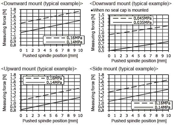
| Measuring force (Note 4) | Downward mount: (Note 5), Upward mount: (Note 5), Side mount: (Note 5) | ||||
| Resolution | 0.5 μm 0.02 mil | 0.1 μm 0.004 mil | |||
| Sampling cycle | 1 ms | ||||
| Indication accuracy (P-P) | Full range: 2.0 μm 0.079 mil or less Limited range: 1.0 μm 0.039 mil or less (any 60 μm 2.362 mil) | Full range: 1.0 μm 0.039 mil or less Limited range: 0.5 μm 0.02 mil or less (any 60 μm 2.362 mil) | |||
| Tip deviation amount | 35 μm 1.378 mil (typical value) | ||||
| Hot swap function | Incorporated | ||||
| Working pressure range | 0.14 to 0.16 MPa | 0.035 to 0.045 MPa | 0.14 to 0.16 MPa | 0.035 to 0.045 MPa | |
| Capacity to resist pressure | 0.2 MPa | ||||
| Usable fluid | Clean air (Dew point temperature: -10 ℃ +14 ℉ or less) | ||||
| Applicable tube | Outside diameter: ø4 mm ø0.157 in / Inside diameter: ø2.5 mm ø0.098 in | ||||
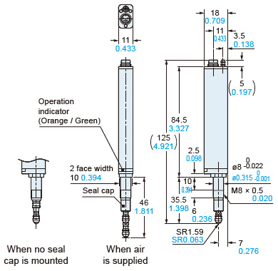
| Operation indicator | Equipped (2-color LED: Orange / Green) | ||||
| Pollution degree | 2 | ||||
| Operating altitude | 2,000 m 6561.68 ft or less (Note 6) | ||||
| Environmental resistance | Protection | IP67 (IEC) (Note 7) | - | IP67 (IEC) (Note 7) | - |
| Ambient temperature | -10 to +55 ºC +14 to +131 ℉ (No dew condensation or icing allowed), Storage: -20 to +60 ºC -4 to +140 ℉ | ||||
| Ambient humidity | 35 to 85 % RH, Storage: 35 to 85 % RH | ||||
| Insulation resistance | 100 MΩ or more at 250 V DC | ||||
| Vibration resistance | 10 to 500 Hz frequency, 3 mm 0.118 in double amplitude (10 to 58 Hz), maximum acceleration 196 m/s2, (58 to 500 Hz) in X, Y, and Z directions for two hours each | ||||
| Shock resistance | 1,960 m/s2 acceleration in X, Y, and Z directions three times each | ||||
| Grounding method | Capacitor grounding | ||||
| Material | Body: Zinc, Holder: Stainless steel, Spindle: Tool steel, Probe (Note 8): Brass (body) / Ceramic (ball), Air tube clamp: S60CM | ||||
| Weight | Net weight: 80 g approx. | ||||
| Accessories | Sensor head fastening wrench: 1 pc., Mounting nut: 1 pc., Seal cap: 1pc, Air tube clamp: 1 pc. | ||||
Notes :
1) Where measurement conditions are not specified, the conditions used were as follows: standard type measurement probe (HG-SS10C), ambient temperature of +20 ℃ +68 ℉, and a clean atmosphere where water, oil, other liquids or dust does not come in contact with the equipment.
2) Be sure to use the sensor in combination with an HG-SC□ controller manufactured in or after February 2019.
3) The position that represents "0" as an absolute value is a position where the spindle is pushed further down from the bottom dead point by 0.1 mm 0.004 in or more. The term "stroke" indicates the total stroke length from the bottom dead point to the top dead point.
4) Measuring force changes with the air pressure used. Removing the seal cap enables the product to be used as the low measuring force type.
5) For the relationship between supplied air pressure and measuring force or between measuring force and pushed spindle position, see the figures below. For upward mount without a seal cap, subtract 0.2 N from the measuring force. For side mount, subtract 0.1 N from the measuring force. The following figures are only typical examples, and these relationships differ depending on the assembly accuracy of the product or the abrasion status of sealing materials.
6) Do not use or store in an environment that has been pressurized to an air pressure higher than the atmospheric pressure at 0 m.
7) Protective structure is not applicable when the sealing portions have deteriorated or become damaged. The protection level is zero when the seal cap is removed.
8) The probe is also available as an option.
10 mm 0.394 in type
| Type | General purpose | High precision | |||
|---|---|---|---|---|---|
| Standard type | Low measuring force type | Standard type | Low measuring force type | ||
| Model No. | HG-S1010 | HG-S1010R | HG-S1110 | HG-S1110R | |
| Applicable regulations | CE Marking (EMC Directive, RoHS Directive), UKCA Marking (EMC Regulations, RoHS Regulations) | ||||
| Compatible controller | HG-SC101(-P), HG-SC111(-P), HG-SC112(-P), HG-SC113 | ||||
| Position detection method | Optical absolute linear encoder method | ||||
| Measurement range | 10 mm 0.394 in | ||||
| Stroke | 10.5 mm 0.413 in or more | ||||
| Measuring force (Note 2) | Downward mount | 1.65 N or less 1.10 N (Note 3) | 0.35 N or less 0.30 N (Note 3) | 1.65 N or less 1.10 N (Note 3) | 0.35 N or less 0.30 N (Note 3) |
| Upward mount | 1.35 N or less 0.85 N (Note 3) | - | 1.35 N or less 0.85 N (Note 3) | - | |
| Side mount | 1.50 N or less 0.95 N (Note 3) | 0.25 N or less 0.20 N (Note 3) | 1.50 N or less 0.95 N (Note 3) | 0.25 N or less 0.20 N (Note 3) | |
| Resolution | 0.5 μm 0.020 mil | 0.1 μm 0.004 mil | |||
| Sampling period | 1 ms | ||||
| Indication accuracy (P-P) | Full range: 2.0 μm 0.079 mil or less Narrow range: 1.0 μm 0.039 mil or less (any 60 μm 2.362 mil) | Full range: 1.0 μm 0.039 mil or less Narrow range: 0.5 μm 0.020 mil or less (any 60 μm 2.362 mil) | |||
| Tip deviation amount | 35 μm 1.378 mil (typical)(Note 4) | ||||
| Hot swap function | Incorporated | ||||
| Operation indicator | 2-color LED (Orange / Green) | ||||
| Pollution degree | 2 | ||||
| Operating altitude | 2,000 m 6561.68 ft or less (Note 5) | ||||
| Environmental resistance | Protection | IP67 (IEC) (Note 6) | - | IP67 (IEC) (Note 6) | - |
| Ambient temperature | -10 to +55 ℃ +14 to +131 ℉ (No condensation or icing), Storage: -20 to +60 ℃ -4 to +140 ℉ | ||||
| Ambient humidity | 35 to 85 % RH, Storage: 35 to 85 % RH | ||||
| Insulation resistance | 100 MΩ or more at 250 V DC | ||||
| Vibration resistance | 10 to 500 Hz frequency, 3 mm 0.118 in double amplitude (10 to 58 Hz), maximum acceleration 196 m/s2, (58 to 500 Hz) in X, Y, and Z directions for two hours each | ||||
| Shock resistance | 1,960 m/s2 acceleration in X, Y and Z directions three times each | ||||
| Grounding method | Capacitor grounding | ||||
| Material | Body | Zinc | |||
| Holder | Stainless steel | ||||
| Spindle | Tool steel | ||||
| Probe (Note 7) | Brass (body) / Ceramic (ball) | ||||
| Rubber bellows | NBR (black) | ||||
| Weight | Net weight: 80 g approx. | ||||
| Accessories | Standard type (HG-S1010 / HG-S1110): Sensor head fastening wrench 1 pc., Mounting nut 1 pc. Low measuring force type (HG-S1010R / HG-S1110R): Sensor head fastening wrench 1 pc., Mounting nut 1 pc., Rubber bellows 1 pc. | ||||
Notes:
1) Where measurement conditions have not been specified precisely, the conditions used were as follows: standard type measurement probe (HG‑SS10C), ambient temperature +20 ℃ +68 ℉, and a clean atmosphere where dust and liquids such as water and oil do not come in contact with the equipment.
2) In the case of low measurement force type (HG-S1010R / HG-S1110R), measurements were obtained with products in standard configuration without rubber bellows.
3) Typical value near center of measurement.
4) Value calculated from the clearance of the upper and lower plain bearings.
5) Do not use or store in an environment that has been pressurized to an air pressure higher than the atmospheric pressure at 0 m.
6) Excludes damage and deterioration to rubber bellows due to external causes.
7) The probes (optional) are also available.
32 mm 1.260 in type
| Type | General purpose | ||
|---|---|---|---|
| Standard | |||
| Model No. | HG-S1032 | ||
| Regulatory compliance | CE Marking (EMC Directive, RoHS Directive), UKCA Marking (EMC Regulations, RoHS Regulations) | ||
| Compatible controller | HG-SC101(-P), HG-SC111(-P), HG-SC112(-P), HG-SC113 | ||
| Position detection method | Optical absolute linear encoder method | ||
| Measurement range | 32mm 1.260 in | ||
| Stroke | 32.5 mm 1.280 in or more | ||
| Measuring force | Downward mount | 2.97 N or less 1.90 N (Note 2) | |
| Upward mount | 2.09 N or less 1.19 N (Note 2) | ||
| Side mount | 2.53 N or less 1.50 N (Note 2) | ||
| Resolution | 0.5μm 0.020 mil | ||
| Sampling period | 1ms | ||
| Indication accuracy (P-P) | Full range : 3.0 μm 0.118 mil or less Narrow range : 2.0 μm 0.079 mil or less (any 60 μm 2.362 mil) | ||
| Tip deviation amount | 40 μm 1.575 mil (typical)(Note 3) | ||
| Hot swap function | Incorporated | ||
| Operation indicator | 2-color LED (Orange / Green) | ||
| Pollution degree | 2 | ||
| Operating altitude | 2,000 m 6561.68 ft or less (Note 4) | ||
| Environmental resistance | Protection | IP67 (IEC) (Note 5) | |
| Ambient temperature | -10 to +55 ℃ +14 to +131 ℉ (No condensation or icing), Storage: -20 to +60 ℃ -4 to +140 ℉ | ||
| Ambient humidity | 35 to 85 % RH, Storage: 35 to 85 % RH | ||
| Insulation resistance | 100 MΩ or more at 250 V DC | ||
| Vibration resistance | 10 to 150 Hz frequency, 3 mm 0.118 in double amplitude (10 to 58 Hz), maximum acceleration 196 m/s2, (58 to 150 Hz) in X, Y, and Z directions for two hours each | ||
| Shock resistance | 1,960 m/s2 acceleration in X, Y and Z directions three times each | ||
| Grounding method | Capacitor grounding | ||
| Material | Body | Aluminum alloy | |
| Holder | Stainless steel | ||
| Spindle | Free-cutting steel | ||
| Probe (Note 6) | Brass (body) / Ceramic (ball) | ||
| Rubber bellows | NBR (black) | ||
| Weight | Net weight: 150 g approx. | ||
| Accessories | Sensor head fastening wrench 1 pc., Mounting nut 1 pc. | ||
Notes:
1) Where measurement conditions have not been specified precisely, the conditions used were as follows: standard type measurement probe (HG‑SS10C), ambient temperature +20 ℃ +68 ℉, and a clean atmosphere where dust and liquids such as water and oil do not come in contact with the equipment.
2) Typical value near center of measurement.
3) Value calculated from the clearance of the upper and lower plain bearings.
4) Do not use or store in an environment that has been pressurized to an air pressure higher than the atmospheric pressure at 0 m.
5) Excludes damage and deterioration to rubber bellows due to external causes.
6) The probes (optional) are also available.
50 mm 1.969 in type
| Type | General purpose | ||
|---|---|---|---|
| Standard type | |||
| Model No. | HG-S1050 | ||
| Applicable regulations | CE Marking (EMC Directive, RoHS Directive), UKCA Marking (EMC Regulations, RoHS Regulations) | ||
| Compatible controller (Note 2) | HG-SC101(-P), HG-SC111(-P), HG-SC112(-P), HG-SC113 | ||
| Position detection method | Optical absolute linear encoder method | ||
| Measurement range | 50 mm 1.969 in | ||
| Stroke | 50.5 mm 1.988 in or more | ||
| Measuring force | Downward mount | 3.8 N or less (50 mm 1.969 in pressing position) 1.9 N (intermediate position) (Note 3) | |
| Upward mount | 3.2 N or less (50 mm 1.969 in pressing position) 1.4 N (intermediate position) (Note 3) | ||
| Side mount | 3.4 N or less (50 mm 1.969 in pressing position) 1.7 N (intermediate position) (Note 3) | ||
| Resolution | 0.5 μm 0.020 mil | ||
| Sampling period | 1 ms | ||
| Indication accuracy (P-P) | Full range: 3.5 μm 0.138 mil or less | ||
| Tip deviation amount | 40 μm 1.575 mil or less (typical) (Note 4) | ||
| Hot swap function | Incorporated | ||
| Operation indicator | 2-color LED (Orange / Green) | ||
| Pollution degree | 2 | ||
| Operating altitude | 2,000 m 6561.68 ft or less (Note 5) | ||
| Environmental resistance | Protection | IP67 (IEC) (Note 6) | |
| Ambient temperature | -10 to +55 ℃ +14 to +131 ℉ (No condensation or icing allowed), Storage: -20 to +60 ℃ -4 to +140 ℉ | ||
| Ambient humidity | 35 to 85 % RH, Storage: 35 to 85 % RH | ||
| Insulation resistance | 100 MΩ or more at 250 V DC | ||
| Vibration resistance | 10 to 55 Hz frequency, 1.5 mm 0.059 in double amplitude in X, Y and Z directions for two hours each | ||
| Shock resistance | 980 m/s2 acceleration in X, Y and Z directions three times each | ||
| Grounding method | Capacitor grounding | ||
| Material | Body | Aluminum alloy | |
| Holder | Free-cutting steel | ||
| Spindle | Carbon tool steel | ||
| Probe (Note 6) | Brass (body) / Ceramic (ball) | ||
| Rubber bellows | NBR (black) | ||
| Weight | Main unit weight: 180 g approx. | ||
| Accessories | Sensor head fastening wrench 1 pc., Mounting nut 1 pc. | ||
1) Where measurement conditions have not been specified precisely, the conditions used were as follows: standard type measurement probe (HG-SS10C), ambient temperature +20 ℃ +68 ℉, and a clean atmosphere where dust and liquids such as water and oil do not come in contact with the equipment.
2) In the case of the 50 mm 1.969 in type (HG-S1050), be sure to connect to an HG-SC□ controller product manufactured in or after February 2019.
3) Typical value near center of measurement.
4) Value calculated from the clearance of the upper and lower plain bearings.
5) Do not use or store in an environment that has been pressurized to an air pressure higher than the atmospheric pressure at 0 m.
6) Excludes damage and deterioration to rubber bellows due to external causes.
7) The probes (optional) are also available.
Controllers
| Type | Master unit | Slave unit | |||
|---|---|---|---|---|---|
| High-performance type | High-performance type | Standard type | Wire-saving type | ||
| Model No. | NPN output | HG-SC101 | HG-SC111 | HG-SC112 | HG-SC113 |
| PNP output | HG-SC101-P | HG-SC111-P | HG-SC112-P | ||
| Applicable regulations | CE Marking (EMC Directive, RoHS Directive), UKCA Marking (EMC Regulations, RoHS Regulations) | ||||
| Compatible sensor head (Note 8) | HG-S1010(R), HG-S1110(R), HG-S1032, HG-S1050, HG-S1010-AC, HG-S1110-AC | ||||
| Number of connectable controllers | Up to 15 slave units can be connected per master unit.(Note 2) | ||||
| Supply voltage | 24 V DC ±10 %, including ripple 0.5 V (P-P) | ||||
| Current consumption (Note 3) | 70 mA or less (when sensor head is connected) | ||||
| Analog current output (Note 4) | ・Current output range: 4 to 20 mA / F.S. (default value) ・Error output: 0 mA ・Linearity: ±0.25 % F.S. ・Load impedance: 250 Ω max. | - | |||
| Control output (Output 1, Output 2, Output 3) | <NPN output type> NPN open-collector transistor ・Maximum sink current: 50 mA(Note 5) ・Applied voltage: 30 V DC or less (between output and 0 V) ・Residual voltage: 1.5 V or less (at 50 mA sink current) ・Leakage current: 0.1 mA or less <PNP output type> PNP open-collector transistor ・Maximum source current: 50 mA(Note 5) ・Applied voltage: 30 V DC or less (between output and +V) ・Residual voltage: 1.5 V or less (at 50 mA source current) ・Leakage current: 0.1 mA or less | - | |||
| Short-circuit protection | Incorporated (automatic reset type) | - | |||
| Judgment output | NO / NC switching method | - | |||
| Alarm output | Open when alarm occurs | - | |||
| External input (Input 1, Input 2, Input 3) | <NPN output type> Non-contact input or NPN open-collector transistor ・Input condition: Invalid (+8 V to +V DC or open) Valid (0 to +1.2 V DC) ・Input impedance: 10 kΩ approx. <PNP output type> Non-contact input or PNP open-collector transistor ・Input condition: Invalid (0 to +0.6 V DC or open) Valid (+4 V to +V DC) ・Input impedance: 10 kΩ approx. | - | |||
| Trigger input | Input time 2 ms or more (ON) | - | |||
| Preset input | Input time 20 ms or more (ON) | - | |||
| Reset input | Input time 20 ms or more (ON) | - | |||
| Bank input A / B(Note 6) | Input time 20 ms or more (ON) | - | |||
| Response time | 3 ms, 5 ms, 10 ms, 100 ms, 500 ms, 1,000 ms switching type | ||||
| Digital display | 204-segment LCD | ||||
| Display resolution | 0.1 μm 0.004 mil | ||||
| Display range | -199.9999 to 199.9999 mm -7.874 to 7.874 in | ||||
| Pollution degree | 2 | ||||
| Operating altitude | 2000 m 6561.68 ft or less(Note 7) | ||||
| Environmental resistance | Protection | IP40 (IEC) | |||
| Ambient temperature | -10 to +50 ℃ +14 to +122 ℉ (No condensation or icing)(Note 5), Storage: -20 to +60 ℃ -4 to +140 ℉ | ||||
| Ambient humidity | 35 to 85 % RH, Storage: 35 to 85 % RH | ||||
| Voltage withstandability | 1,000 V AC for one min. between all supply terminals connected together and enclosure | ||||
| Insulation resistance | 20 MΩ, or more, with 250 V DC megger between all supply terminals connected together and enclosure | ||||
| Vibration resistance | 10 to 150 Hz frequency, 0.75 mm 0.030 in double amplitude (10 to 58Hz), maximum acceleration 49 m/s2 (58 to 150 Hz) in X, Y and Z directions for two hours each | ||||
| Shock resistance | 98 m/s2 acceleration (10 G approx.) in X, Y and Z directions five times each | ||||
| Material | Case: Polycarbonate, Cover: Polycarbonate, Switches: Polyacetal | ||||
| Cable | 0.2 mm2 2-core cable (brown and blue lead wires) / 0.15 mm2 7‑core composite cable, 2 m 6.562 ft long | 0.15 mm2, 7‑core composite cable, 2 m 6.562 ft long | 0.15 mm2, 6‑core cabtyre cable, 2 m 6.562 ft long | - | |
| Weight | Net weight: 140 g approx. | Net weight: 140 g approx. | Net weight: 130 g approx. | Net weight: 60 g approx. | |
Notes:
1) Where measurement conditions have not been specified precisely, the conditions used were as follows: supply voltage 24 V DC, ambient temperature +20 ℃ +68 ℉.
2) When a digital displacement sensor communication unit is connected, a maximum of 14 slave units can be connected per master unit.
3) Current consumption does not include analog current output.
4) Linearity F.S. = 16 mA, and is linearity with respect to digitally measured values.
5) When slave units are connected to the master unit, the maximum sink current / source current of the control output and ambient temperature vary depending on the number of connected slave units as shown below.
| Number of connected slave units | Maximum sink current / source current of control output | Ambient temperature |
|---|---|---|
| 1 to 7 units | 20 mA | -10 to +45 ℃ +14 to +113 ℉ |
| 8 to 15 units | 10 mA |
6) Banks 1 to 3 can be selected by switching bank input A / B.
7) Do not use or store in an environment that has been pressurized to an air pressure higher than the atmospheric pressure at 0 m.
8) Always connect the Air-driven type (HG-S1010-AC / HG-S1110-AC) and the 50 mm 1.969 in type (HG-S1050) to an HG-SC□ controller manufactured February 2019 or later.
HG-S series' self-monitoring function
* Please use a controller (HG-SC□) manufactured from February 2019 or later when self-monitoring function is preferred.
| Status | Response parameter | Measures | Controller HG-SC□ | |
|---|---|---|---|---|
| Error code (Note) | Measurement alarm (Note) | |||
| Notification | Sensor head unconnected | Status check | E200 | — |
| Connected unit count check error | Status check | E160 (For master units only) | — | |
| NPN / PNP output type mixture error | Status check | E100 (For master units only) | — | |
| Calculated unlit count error | Status check | E110 (For master units only) | — | |
| Copy executionerror (Slave unit problem) | Status check | E170 (For master units only) | — | |
| The thrust on the sensor head stroke is above the specified range | Status check | E210 | — | |
| Pressure check | Status check | — | Alarm | |
| Catch check | Status check | — | Alarm | |
| Fault | Controller memory function damaged | Controller replacement | E600 | — |
| E610 | ||||
| E620 | ||||
| Sensor Head memory function damaged | Sensor head replacement | E630 | — | |
| Output section short-circuit error | Status check / Replacement | E700 | — | |
| Detection circuit damaged | Sensor head replacement | E240 | — | |
| System error | Controller replacement | E900 | — | |
| E910 | ||||
| E911 | ||||
| E912 | ||||
| E920 | ||||
Note:Error codes and alarms are displayed on HG-SC□ controllers.
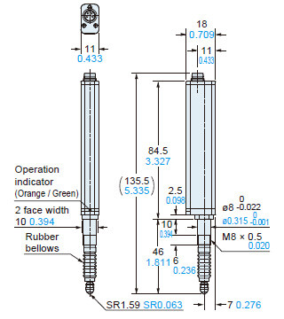
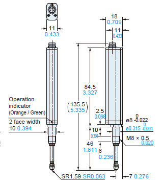
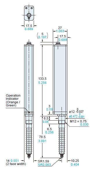
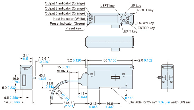
Dimensions
- Unit: mm in
HG-S1010-AC HG-S1110-AC
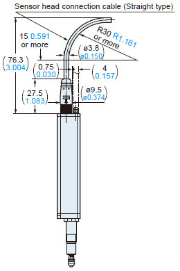
Sensor head (Air-driven type)
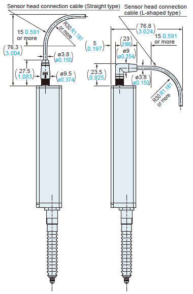
Installation of sensor head connection cable
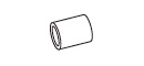
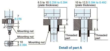
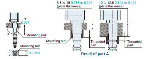
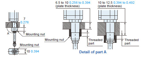
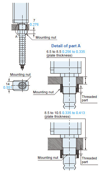
Installation of mounting nut attachment
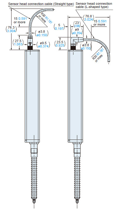
HG-S1010(R) HG-S1110(R)
Sensor head
Standard type
HG-S1010 / HG-S1110
Low measuring force type
HG-S1010R / HG-S1110R
Installation of mounting nut attachment
Standard type
HG-S1010 / HG-S1110
Low measuring force type
HG-S1010R / HG-S1110R
Installation of sensor head connection cable
The diagrams show the sensor head connection cable connected to the low measurement force type.

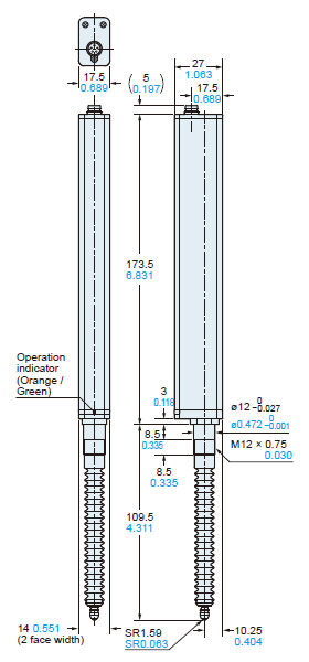
HG-S1032
Sensor head
Installation of mounting nut attachment
Installation of sensor head connection cable
HG-S1050
Installation of mounting nut attachment
Installation of sensor head connection cable
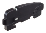
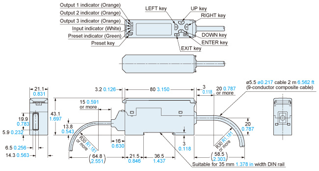
HG-SC101(-P)
Controller (Master unit)
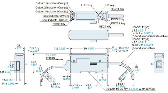
HG-SC111(-P) HG-SC112(-P)
Controller (Slave unit)
HG-SC113
Controller (Slave unit)
MS-DIN-E
End plate (Optional)
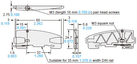
Material: Polycarbonate
I/O Circuit and Wiring diagrams
NPN output type
HG-SC101 / Master unit
HG-SC111 / Slave unit
HG-SC112 / Slave unit
*1 Non-voltage contact or NPN open collector transistor

0 to +1.2 V DC: Effective
+8 V to +V DC or open: Ineffective
Note: Use shielded wire for the analog output.
PNP output type
HG-SC101-P / Master unit
HG-SC111-P / Slave unit
HG-SC112-P / Slave unit
*1 Non-voltage contact or PNP open collector transistor
+4 V to +V DC: Effective 0 to +0.6 V DC or open: Ineffective
Note: Use shielded wire for the analog output.
- This website is a guide to select a suitable product. Be sure to read instruction manual of the product prior to its use.
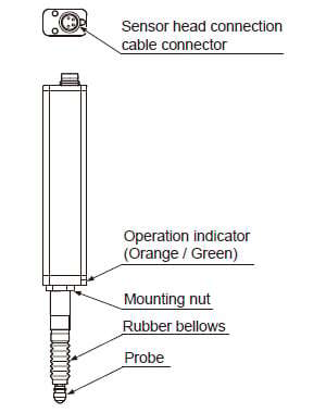
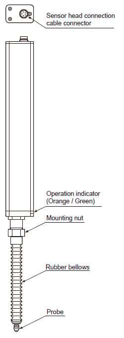
Part description
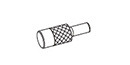
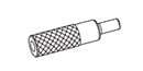
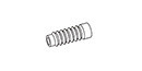
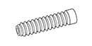
Sensor head
<Standard type>
(HG-S1010 / HG-S1110)
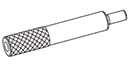
<Low measuring force type>
(HG-S1010R / HG-S1110R)
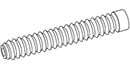
<Standard type>
(HG-S1032)
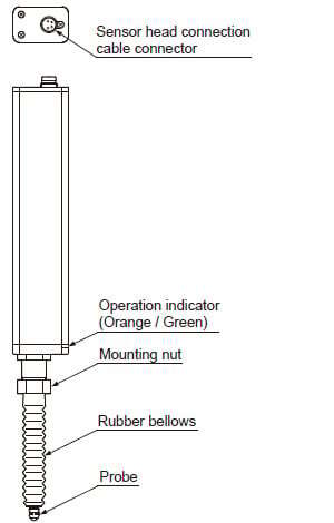
<Standard type>
(HG-S1050)
Controller
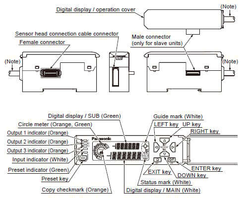
Note: Not provided on slave units or wire-saving type (HG-SC113).
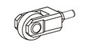
Sensor head (Air-Driven Type)
Air circuit (recommended)
・When using air-driven type sensor heads (HG-S1010-AC, HG-S1110-AC), configure an air circuit similar to the one shown in the diagram below, and adjust the spindle speed using the speed control valve as needed.
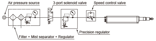
Notes :
1)Supply clean air (free from moisture, oil, dust, or other foreign objects) to this product.
2)Air pressure may decrease, depending on the length of the air pipe from the air supply source or any pneumatic components (such as needle valves, speed controllers, or mini-filters) that are added. Take care to ensure that air pressure supply to the product is sufficient. Select pneumatic components suitable for the supplied air pressure.
3)The 3-port solenoid valve and speed control valve have their respective mounting directions. Mount each valve in their correct direction by referring to the diagram on the left.
4)A filter with a rated filtration of 5 μm 0.197 mil or less and a mist separator with a rated filtration of 0.3 μm0.012 mil or less are recommended.
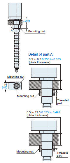
Sensor head
Mounting
・When tightening the nut, take care not to damage the rubber bellows.
・If the rubber bellows is deformed, a load will occur when the spindle operates and damage may result.
・Do not remove the rubber bellows from the standard type products (HG-S1010 / HG-S1110 / HG-S1032 / HG-S1050) except for when replacing them. Unnecessary removal of rubber bellows can result in entry of dust and water, thus causing malfunction.
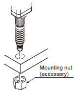
1.Open a hole in the housing in which the sensor head will be mounted.
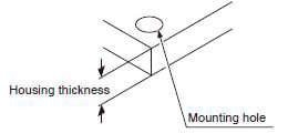
| Mounting hole | Housing thickness | |
|---|---|---|
| HG-S1010(R), HG-S1110(R) | ø8H7( +0.0150 )mm | 6.5~12.5mm |
| HG-S1032 | ø12H7( +0.0180 )mm | 6.5~10.5mm |
| HG-S1050 | 6.5~12.5mm |
2.Insert the sensor head into the hole you opened in the housing, and fasten provisionally with the provided mounting nut.
Note:The orientation of the mounting nut depends on the thickness of the housing. For details, refer to "Demensions"
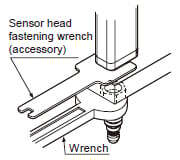
3.Fasten the sensor head.
When fastening the sensor head, tighten the mounting nut with a wrench while holding the sensor head in place with the provided sensor head fastening wrench as shown right.
Tighten to a torque of 12.5 N·m or less. (HG-S1032 / HG-S1050 : 15 N·m or less)
4.Make sure that the rubber bellows has not become deformed as shown right.
If the rubber bellows is deformed, restore the normal shape by rotating the bellows or otherwise.
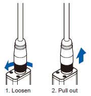
Attaching the sensor head connection cable
・When disconnecting, always make sure that the fastening ring has been completely loosened before pulling out the cable.
・Risk of damage if you pull the cable with excessive force (15 N or more) with the fastening ring tightened.
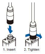
Mounting
1.Insert the sensor head connection cable into the connector for the sensor head connection cable on the sensor head.
2.Turn the fastening ring on the sensor head connector in the direction shown to fasten the ring.
Removal method
1.Turn the fastening ring on the sensor head connector in the direction of the arrow to loosen the ring.
2.Grasp the sensor head connector and pull up to remove.
Controller
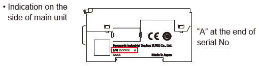
How to identify newer and older controllers, and combinations with sensor heads
- Air-driven type sensor heads and HG-S1050 must be used in combination with HG-SC□ controllers manufactured in or after February 2019.
- If the HG‑SC□ controller is used together with the HG‑TC□ controller for thru-beam type digital displacement sensor HG-T series, make sure to use the HG-SC□ controller manufactured in or after February, 2019. Furthermore, connect the slaves units of the same series to the side closer to the master unit and the slave units of the other series to the far side.
- When connecting only HG-S series controllers, both newer and older controllers can be connected.
How to identify newer controllers (manufactured in or after February 2019)
Combinations with sensor heads
| Combination | Newer controller | Older controller | ||
|---|---|---|---|---|
| Manufactured in or after February 2019 | Manufactured in or before January 2019 | |||
| HG-SC□ | HG-SC□ | |||
| Sensor head | HG-S1010(R) | Possible | Possible | |
| HG-S1110(R) | ||||
| HG-S1032 | ||||
| HG-S1050 | Possible | Not possible | ||
| Air-driven type | HG-S1010-AC | Possible | Not possible | |
| HG-S1110-AC | ||||
![]()
Please refer to the page below when using HG-S controllers and HG-T controllers connected.
>>With regards to the connected use of HG-S and HG-T
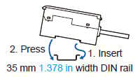
Mounting
Mounting
1.Insert the rear of the mounting part into the DIN rail.
2.While pressing down on the rear of the mounting part, insert the front of the mounting part into the DIN rail.
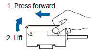
Removal method
1.Grasp the product and push forward.
2.Lift the front to remove.
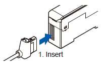
Attaching the sensor head connection cable
Mounting
1.Insert the sensor head connection cable into the connector for the sensor head connection cable on the controller.
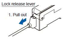
Removal method
1.Grasp the controller, and while pressing on the lock release lever on the connector of the sensor head connection cable, pull toward you to disconnect.
Note:If you attempt to disconnect the cable by pulling it without pressing the lock release lever, cable wire breakage and connector damage may occur.
Connection
・Always shut off the power before connecting a slave unit to or disconnecting a slave unit from the master unit. Risk of controller damage if you attempt connection with the power on.
・Insert the male connector firmly into the female connector. Risk of controller damage if not completely connected.
・To connect units, the units must be mounted on a DIN rail. Attach end plates MS-DIN-E (optional) so as to enclose the connected units at the ends.
・Up to 15 slave units (up to 14 slave units when a communication unit for digital displacement sensor is connected) can be connected per master unit.
・When connecting slave units to a master unit, connect only NPN output types, or only PNP output types. Dissimilar output types cannot be connected together.
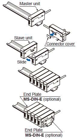
Connection method
1.Mount one master unit on the DIN rail.
2.Remove the connector cover.
3.Mount each slave unit one at a time on the DIN rail. Remove all connector covers except for the cover on the end slave unit.
4.Slide each slave unit to connect the female and male connectors.
5.Attach end plates MS-DIN-E (optional) with the flat side facing in so as to enclose the connected units at the ends.
6.Tighten the screws to fasten the end plates.
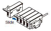
Removal method
1.Loosen the screws on the end plates.
2.Remove the end plates.
3.Slide and remove the controllers, one at a time.
Common
Wiring
・The product is designed to fulfill the specifications when combined with the HG-S□ sensor head and HG-SC□ controller. If the product is used in combination with other products, it not only fails to meet the specifications but also generates a malfunction in some cases.
・For the controller DC power supply, only use a power supply that is isolated by means of an isolation transformer or otherwise.
・Risk of short-circuiting and damage to the controller or power supply if a transformer such as an auto transformer is used. Risk of short-circuiting and damage to the controller or power supply if incorrectly mounted or connected.
- Make sure that the power supply is off while performing wiring or expansion work.
- After you have completed wiring work, check the wiring carefully before switching on the power.
- Do not run the wires together with high-voltage lines or power lines or put them in the same raceway. This can cause malfunction due to induction.
- Verify that the supply voltage fluctuations are within the rating.
- If power is supplied from a commercial switching regulator, ensure that the frame ground (F.G.) terminal of the power supply is connected to an actual ground.
- Do not use during the initial transient time after the power supply is switched ON.
- Make sure that stress by forcible bend or pulling is not applied directly to the sensor cable joint.
Others
- This device has been developed / produced for industrial use only.
- Do not use this product outside the range of the specifications. Risk of an accident and product damage. There is also a risk of a noticeable reduction of service life.
- This controller uses an EEPROM. The EEPROM has a service life of one million setting operations.
- This product is suitable for indoor use only.
- Avoid dust, dirt, and steam.
- Take care that the product does not come in direct contact with organic solvents such as thinner.
- Take care that the product does not come in direct contact with strong acid or alkaline.
- Take care that the product does not come in direct contact with oil or grease.
- Do not use in an environment containing inflammable or explosive gases.
- Performance may not be satisfactory in a strong electromagnetic field.
- This product is a precision device. Do not drop or otherwise subject to shock. Risk of product damage.
- Never attempt to disassemble, repair, or modify the product.
- Mount the sensor unit perpendicular to the measured surface. Mounting the sensor unit obliquely may not only result in measurement error but also significantly shorten its service life.
- Do not allow excessive horizontal force to be applied to the spindle. This may cause reduced accuracy and durability.
- Mount a pressure-reducing valve to use the product within the allowable working pressure range. Excessive pressure may result in failure or damage.
- Do not use air containing foreign objects (such as dust), water, or oil. Doing so may result in electric shock or failure. To prevent such problems, take appropriate measures such as mounting air filters or mist separators.
- Before performing maintenance, inspection, or cleaning, always shut off air supply completely and check that the pressure inside the product and piping is zero. Failure to do so may result in accidents or failures due to air pressure.
- Sensor head connection cable with L-shape connector CN-HS-C□L (optional) cannot be used with an air-driven type sensor head.