------------------------------ Tab1 showing ------------------------------
Discontinued Products

------------------------------ Tab2 showing ------------------------------
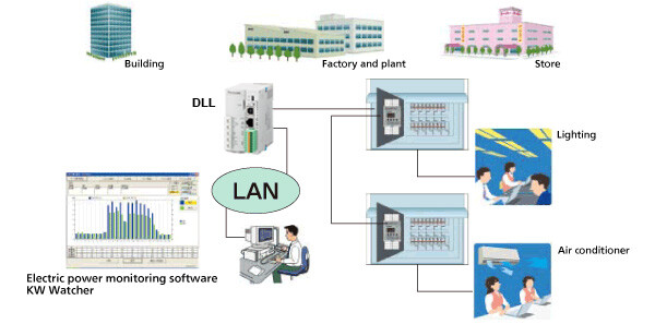
System Configuration
1. Power monitoring of machine

2. Power monitoring of lighting and air conditioner
------------------------------ Tab3 showing ------------------------------
------------------------------ Tab4 showing ------------------------------
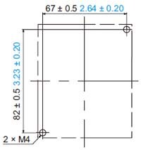
Dimensions
- Unit: mm in
KW1M-H
AKW1121B

Mounting hole dimensions
Note : Please keep space that the thumb enters for the battery exchange at the left of the main unit (about 30mm).
Dedicated current transformers CT
Dedicated current transformer (CT) Clamp-on type 5A/50A (AKW4801B)
Dedicated current transformer (CT) Clamp-on type 100A (AKW4802B)
Dedicated current transformer (CT) Clamp-on type 250A (AKW4803B)
Dedicated current transformer (CT) Clamp-on type 400A (AKW4804B)
Dedicated current transformer (CT) Clamp-on type 600A (AKW4808B)
Dedicated current transformer (CT) Through type 50A/100A (AKW4506B)
Dedicated current transformer (CT) Through type 250A/400A/600A (AKW4507B/AKW4508B)
Terminal arrangement・Wiring diagrams
Terminal arrangement
Be sure to wire correctly according to the terminal arrangement and wiring diagrams.
After completing wiring, be sure to attach the terminal cover for safety reasons.
Caution for Wiring
1) Terminal fastening torque should be 0.5 to 0.6N・m. In case of using a crimping terminal, use it with insulating sleeve applicable to M3 screw.
2) This has no built-in power switch, circuit breaker for power supply part. To protect the device, it is necessary to install power switch and circuit breaker in the power supply circuit.
And this has no built-in power switch, circuit breaker or fuse for measured voltage input parts.
Therefore it is necessary to install them in the circuit near this unit.
3) We recommend a wire with the cross section of 0.75 to 1.25mm2 for power supply line and measured voltage input line.
4) Use flame-resistant cable for each wiring.
Wiring diagrams
When measuring load with rated input voltage (100 to 200 V AC system and 400 V AC system)
·Single-phase two-wire system
*One dedicated current transformer (CT) is required.
Note: Do not wire to (6), (7) terminal. They are connected internal.
·Single-phase three-wire system / Three-phase three-wire system
*Two dedicated current transformers (CT) are required.
Note: Do not wire to (7) terminal.They are connected internal.
·Three-phase four-wire system
*Three dedicated current transformers (CT) are required.
When measuring a load with exceed input voltage
Voltage transformer (VT) is needed when you measure a load with over rated input voltage (440V).Use VT, those secondary rating is 110V.
Grounding the secondary side of VT and CT is not necessary with low-voltage circuit.
- Single-phase two-wire system
- Single-phase three-wire system / Three-phase three-wire system
- Three-phase four-wire system
Discontinued products [Order accepted till December, 2016]
AKW1121
Mounting hole dimensions
Dedicated current transformer (CT) Clamp-on type 5A/50A (AKW4801C)
Dedicated current transformer (CT) Clamp-on type 100A (AKW4802C)
Dedicated current transformer (CT) Clamp-on type 250A (AKW4803C)
Dedicated current transformer (CT) Clamp-on type 400A (AKW4804C)
Dedicated current transformer (CT) Clamp-on type 600A (AKW4808C)
Dedicated current transformer (CT) Through type 50A/100A (AKW4506C)
Dedicated current transformer (CT) Through type 250A/400A/600A (AKW4507C/AKW4508C)
|
|
| |||||||||
------------------------------ Tab5 showing ------------------------------
Cautions For Use
*Please refer to each manual for the precautions in using.
Avoid locations subject to flammable or corrosive gases, excessive dust, oil, vibrations, or excessive shocks.
Although the case is made from fireproof resin, do not mount it next to flammable materials. Also, avoid placing it directly on top of materials that catch fire easily.
Since the cover for main unit is made of polycarbonate resin, avoid contact with or use in environments containing methyl alcohol, benzene, thinners, and other organic solvents; and ammonia, caustic sodas, and other alkaline substances.
This product is designed to be used only with our options. Options from other companies are not compatible.
Measurement
- Accurate measurement may not be possible if harmonics or waveforms are distorted. Therefore, please test on actual equipment before using.
- Do not use the secondary circuit of the inverter. It causes heat and malfunctions in the main unit.
Surge
- If the operating power supply surge exceeds the following value, the internal circuit could be destroyed, so be sure to use a surge absorption element.
| Surge voltage | KW1M series | Other series |
|---|---|---|
| 4,000 V | 6,000 V |
The values in the graph are the surge-voltage resistance at ±(1.2 × 50) μs of single-polarity full-wave voltage.
Surge wave form [±(1.2/50) μs single-polarity full-wave voltage]

- External noise up to the level shown below is treated as noise voltage, but levels higher than this could lead to malfunctioning or damage to the internal circuit.
| Operating power supply terminals | |
|---|---|
| Noise voltage | 1,500V |
Noise wave form (noise simulator)
Rise time: 1 ns Pulse width: 1 μs, 50 ns
Polarity: ± Cycle: 10 ms
(Note 1): Accurate measurement may not be possible if excessive noise gets added to the input line.
Self-diagnostic function
If an error occurs, the following displays will be given.
| Display | Meaning | Output status | Restoration procedure | Status after restoration |
|---|---|---|---|---|
| ERR00 | CPU error | OFF | Turn the power off and then on again. | The display at start-up before the CPU malfunction occurred. |
| ERR01 | Memory error (Note 2) | EEPROM life ended. Replace the main unit. | - |
(Note 2):
Includes the possibility that the EEPROM's life has expired.
Power failure memory
- Eco-POWER METER memories integrated electric power and working status to internal EEPROM until when power supply is off. (Power failure guarantee)
And every time to change each setting, each setting value is memorized to internal EEPROM at the same time. Therefore, change setting frequently makes EEPROM's life short. Avoid to usage like this.
Others
- Eco-POWER METER is designed chiefly to manage saving energy. It is neither intended nor can it be legally used for billing.
Wiring
Please make sure to check wiring in dimensions page in each product page.
Note:
Please connect a breaker (3 to 15A) to the voltage input part for safety reasons and to protect the device. Grounding the secondary side of VT (Voltage transformer) and CT (Current transformer) is not necessary with low-voltage circuit.
Regarding dedicated current transformers(In AKW8115, dedicated current transformers are not used,therefore, please confirm the respective user's manual.)
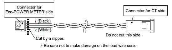
HOW to attach the Current Transformer (CT)
- In case the Eco-POWER METER has connectors for CT, connect to the Eco-POWER METER as it is.
- In case the Eco-POWER METER has screw terminals for CT (KW4M and KW8M), cut the connector for Eco-POWER METER side. Refer to the below.
<Process drawings>
- The below number of CT is required.
For single-phase, two-wire system; 1 pc.
For single-phase, three-wire system; 2 pcs.
For three-phase, three-wire system; 2 pcs.
For three-phase, four-wire system; 3 pcs.
All using CT for one Eco-POWER METER should have the same rating. - Check beforehand that the thickness of the load electric wire is smaller than the through hole of the CT.
- Do not attach CT to the part which a conductor is exposed, such as a bus bar in a control box.
It might cause an electric shock. - When connecting CT, connect the secondary side to the terminal of the Eco-POWER METER first, and after that wire the primary side to a load electric wire. Incorrect order might cause an electric shock or break CT.
- CT has polarity. Align according to the direction (K → L) written on the CT and install from the power source side (K) facing the load side (L). If the direction is incorrect, accurate measurement is impossible.
- When installing and closing CTs, please confirm there is no dust or foreign matter on the separating surfaces. In addition, verify that the separating surfaces are making perfect contact when the CT is closed. Measurement errors will occur if there is a gap in the separating surfaces. (Only Clamp-on type)
- If there is some distortion by harmonic or waveform, it may not measure correctly. Please check with the actual system before adopting it.
- Separate the wiring (strong electric part) of the measured voltage input terminal (operating power supply terminal) from the CT cable. It may not satisfy the accuracy due to noise.
When CT's cable is extended
- Extension of the cable is possible up to approximately 10 m 32.808 ft if the environment is completely free from noise such as external and line induction noise, and the cable has a thickness of at least 0.75 mm2. When extending the cable, use as thick a cable as possible.
*When extending the cable, please perform testing under actual conditions before using.
To connect CT with secondary side current 5 A
How to connect for measuring by combination with CT (secondary side current 5 A)
- Select 5 A at CT type setting mode (CT-T).
- Set the primary current of measured CT (secondary side current 5 A) at primary side current of CT setting mode (CT-1). If the measured CT is 400 A / 5 A, set to "400".
- Clamp the dedicated CT for 5 A, which is connected to the main unit first, to secondary side of the CT. CT direction (K → L) should be set for the CT direction.
- Please set the CT (secondary side current 5 A CT) and, the dedicated CT for 5A, approximately 1 m 3.281 ft apart. If the two CTs are set too close each other, it may not measure accurately due to magnetic field interference.
(Connection example)
With ammeter etc.
Without ammeter

Input connection [except AKW7111B and AKW1110B]
- Contact input
Use highly reliable metal plated contacts. Since the contact's bounce time leads directly to error in the count value, use contacts with as short a bounce time as possible. In general, select 30 Hz for max. counting speed. - Non-contact input (Transistor input)
Connect with an open collector. Use the transistor with the following specifications.
VCEO=min. 20 V, IC=min. 20 mA, ICBO= max. 6 μA
Use transistors with a residual voltage of less than 1.5 V when the transistor is ON.
Note:
Short-circuit impedance should be less than 1 kΩ. (When the impedance is 0 Ω, drain current is approx, 7 mA. The opencircuit impedance should be more than 100 KΩ.)
- Input wiring
Please use shielded wire or metal wire-ways exclusively and a wire length of 10 m 32.808 ft or less. If the wiring length is longer, the impact due to floating capacitance may result in abnormal operation.
Note:
Operating power supply input part and measured voltage input are not insulated to pulse input parts.So the input equipment must have the power supply transformer in which the secondary side is not grounded with the primary and secondary sides insulated, in order to prevent interference of the power supply circuit when connecting the external input circuit. Be sure not to use an auto-transformer.
Output connection
Since the transistor output is insulated from the internal circuit by a photo-coupler, it can be used both as a NPN output and PNP (equal value) output.
Crimping terminal
please make sure to check crimping terminal in dimensions page in each product page.
Low Voltage Directive
When using in the application confirming to EN61010-1/IEC61010-1, make sure to satisfy the following conditions.
(1)
Pulse output part secure only basic insulation. In order to secure reinforced (double) insulation demanded by EN 61010-1/ IEC61010-1, secure basic insulation or more with load side and reinforced (double) insulation with communication system side.
(2)
Provide the voltage input part with an EN60947-1 or EN60947-3 compliant circuit breaker. The breaker that connects to the voltage input part must arrange at the position easily reached, and display shows it is the breaker of the equipment.
(3)
Use a wire with basic insulation or more for a wire cramped (or connected) CT.
【Environmental conditions】
- Overvoltage category II, Pollution degree 2
- Indoor use
- An ambient temperature of –10 to 50℃
- An ambient non-condensing humidity of 35 to 85%RH (at 20℃)
- Altitude of 2000m or less
【Mount the product in a place with】
- A minimum of dust, and an absence of corrosive gases
- No flammable, explosive gasses
- Few mechanical vibrations or shocks
- No exposure to direct sunlight
- No large capacity electromagnetic switches or cables through which large current is flowing